Advertisement
Quick Links
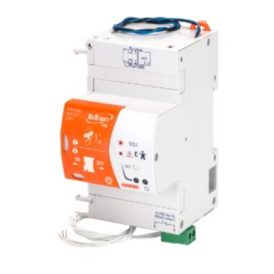
90 RESTART
DISPOSITIVO DI RICHIUSURA AUTOMATICA REGOLABILE PER INTERRUTTORI MODULARI - ADJUSTABLE AUTOMATIC RESET DEVICE FOR
MODULAR CIRCUIT BREAKERS - REGULOVATELNÉ ZAŘÍZENÍ PRO AUTOMATICKOU OBNOVU FUNKCE MODULÁRNÍCH PŘÍSTROJŮ
ACCOPPIAMENTO - COUPLING - SPOJOVÁNÍ
N
L1
L2 L3
L1
L2 L3
N
RM TOP
+
Negli accoppiamenti con interruttori 1P e 3P la maniglia motore in eccedenza deve essere tagliata.
Any excess motor handle after coupling with switches 1P and 3P must be cut off.
Při spojování s jističi 1P a 3P, musí být rukojeť motor.pohonu zkrácena
OK
7 8 9 10 11 12
NO
MTC 1...4P
MT 1...4P
MDC 2...4P
MT+BD 2...4P
1
3
2
1
RESTART RM TOP
3P
56mm
1P
27mm
4P
2P
Advertisement

Related Manuals for Gewiss RESTART RM TOP 90


Summary of Contents for Gewiss RESTART RM TOP 90
- Page 1 90 RESTART RESTART RM TOP DISPOSITIVO DI RICHIUSURA AUTOMATICA REGOLABILE PER INTERRUTTORI MODULARI - ADJUSTABLE AUTOMATIC RESET DEVICE FOR MODULAR CIRCUIT BREAKERS - REGULOVATELNÉ ZAŘÍZENÍ PRO AUTOMATICKOU OBNOVU FUNKCE MODULÁRNÍCH PŘÍSTROJŮ ACCOPPIAMENTO - COUPLING - SPOJOVÁNÍ L2 L3 7 8 9 10 11 12 L2 L3 MTC 1...4P RM TOP...
- Page 2 TEST DI CORRETTO ACCOPPIAMENTO - CORRECT COUPLING TEST - TEST SPRÁVNÉHO PŘIPOJENÍ I-ON 0-OFF...
- Page 3 INSTALLAZIONE - INSTALLATION - INSTALACE Modulo di controllo del cortocircuito Short circuit detection module Modul kontroly zkratu...
- Page 4 Il modulo di rilevamento del cortocircuito può essere installato sia a monte che a valle dell’interruttore. The short-circuiting detection module can be installed either upstream or downstream from the circuit breaker. Modul kontroly zkratu může být instalován shora či ze spodu jističe Nel caso l’interruttore sia affiancato da un blocco differenziale, il modulo non può...
- Page 5 Nelle configurazioni trifase il neutro deve essere sempre collegato nell’ultimo polo a sinistra dell’interruttore. L2 L3 In three-phase configurations the neutral must always be connected in the last pole to the left of the switch. Při konfiguraci 3-F, vodič N musí být vždy připojen na poslední pól jističe vlevo. Intervenire solo ad impianto sezionato e quindi con dispositivo non inserito (porre il selettore in posizione di lucchettato).
- Page 6 230V~ RESET OPEN CLOSE 2,5 mm² 0,4 Nm 2,5 mm² 0,4 Nm 2,5 mm² 0,4 Nm AUX1 2,5 mm² 0,4 Nm AUX2...
- Page 7 7 8 9 10 11 12 Nel caso non sia sufficiente lo spazio per l’installazione del modulo di rilevamento cortocircuito, è possibile delocalizzarlo sulla guida DIN tramite morsetti (non inclusi nel kit). If there is not enough space to install the short-circuiting detection module, you can delocalise it on the DIN rail, through terminals (not supplied with the kit).
- Page 8 INSTALLAZIONE / POSSIBILI CONFIGURAZIONI - INSTALLATION / POSSIBLE CONFIGURATIONS - INSTALACE/MOŽNÉ KONFIGURACE MT+BD 1 2 3 4 5 6 7 8 9 10 1112 1 2 3 4 5 6 7 8 9 10 1112 1 2 3 4 5 6 7 8 9 10 1112 1 2 3 4 5 6 7 8 9 10 1112 1 2 3 4 5 6 7 8 9 10 1112 1 2 3 4 5 6 7 8 9 10 1112...
- Page 9 L’installazione di RM TOP accoppiato con MTC, richiede la delocalizzazione del modulo di rilevamento del corto circuito. The installation of the RM TOP coupled with the MTC requires the delocalisation of the short-circuit detection module. Instalace RM TOP s připojeným kompaktním jističem MTC, vyžaduje jiné umístění modulu kontroly zkratu E’...
- Page 10 ATTIVAZIONE/DISATTIVAZIONE RM TOP - ACTIVATION/DEACTIVATION RM TOP - AKTIVACE/DEAKTIVACE RM TOP RM TOP OFF RM TOP LOCKED RM TOP ON I - O 0 - O I-ON I-ON I-ON 0-OFF 0-OFF 0-OFF LED OFF LED ON LED OFF Impostando il selettore in posizione di OFF o di lucchettato il dispositivo è disattivato. Setting the selector to the OFF or locked position, the device is deactivated.
- Page 11 RICHIUSURA AUTOMATICA CON VERIFICA PREVENTIVA DELL IMPIANTO - AUTOMATIC RESET WITH PREVENTIVE SYSTEM CHECK - AUTOMATICKÝ RESTART S PREVENTIVNÍ KONTROLOU OBVODU Regolare il selettore R in base al valore di I∆n dell’interruttore differenziale accoppiato. Adjust the selector R on the basis of the value of I∆n of the associated residual current circuit breaker. Nastavte přepínač...
- Page 12 IN CASO DI INTERVENTO DELL INTERRUTTORE - SHOULD THE CIRCUIT BREAKER TRIP - V PŘÍPADĚ INTERVENCE MODULÁR. PŘÍSTROJE...
- Page 13 RICHIUSURA AUTOMATICA SENZA VERIFICA PREVENTIVA DELL IMPIANTO - AUTOMATIC RESET WITHOUT PREVENTIVE SYSTEM CHECK - AUTOMATICKÝ RESTART BEZ PREVENTIVNÍ KONTROLY OBVODU Impostare tramite il selettore R il numero massimo di richiusure automatiche successive. By means of the selector R, set the maximum number of consecutive automatic reset operations. Nastavte přepínač...
- Page 14 SEGNALAZIONE DEI LED LED SIGNALS - SIGNALIZACE LED contact 1 contact 2 rosso - red - Červená verde - green - Zelená RESTART OFF (OFF*) Contatto ausiliario configurato per segnalazione di scattato relè. Auxiliary contact configured to indicate shunt trip release. Pomocný...
- Page 15 contact 1 contact 2 rosso - red - verde - green - Červená Zelená RESTART ON (OFF*) Verifica impianto riarmo auto- matico Automatic reset system check (ON*) Probíhá automatické ověření obnovy funkce Stato d’attesa per guasto impianto (15’) (ON*) Wait status installation fault (15’) Stav čekání...
- Page 16 Nel caso la segnalazione dei LED non dovesse corrispondere a quanto riportato in tabella a pag. 15 contattare un tecnico specializzato. If the LED light signalling does not correspond with the indications in the table pag. 15, contact a specialised technician. Pokud signalizace LED neodpovídá...
- Page 17 CONFIGURAZIONE CONTATTO AUX1 - AUX1 CONTACT SETUP - NASTAVENÍ KONTAKTU AUX1 È possibile configurare il contatto ausiliario premendo per almeno 5s il tasto R e poi rilasciandolo. Il passaggio tra le diverse modalità è confermato con lampeggi rossi del LED di sinistra The auxiliary contact can be configured by pressing the button key R for at least 5s, then releasing it.
- Page 18 CONFIGURAZIONE CONTATTO AUX2 - AUX2 CONTACT SETUP - NASTAVENÍ KONTAKTU AUX2 Segnalazione di scattato relè. Fault signalling. Signalizace vypnutí relé (závada) I - O Segnalazione aperto-chiuso. 0 - O Open – closed signalling. Signalizace rozepnuto-sepnuto...
- Page 19 CARATTERISTICHE TECNICHE - TECHNICAL FEATURES - TECHNICKÉ PARAMETRY Sistema di distribuzione: TT – TN - (IT riarmo senza controllo impianto) Tensione nominale di impiego Ue: 230Vac Potenza assorbita a vuoto: 15VA (cosϕ=0,06) Potenza assorbita in fase di riarmo: 30VA (cosϕ=0,65) Potenza dissipata a In: potenza dissipata dell’interruttore associato Tensione di isolamento verso massa: 2500Vac per 1 minuto Tensione nominale di tenuta ad impulso Uimp: 4kV...
- Page 20 According to article 9 paragraph 2 of the European Directive 2004/108/EC and to article R2 paragraph 6 of the Decision 768/2008/EC, the responsible for placing the apparatus on the Community market is: GEWISS S.p.A Via A. Volta, 1 - 24069 Cenate Sotto (BG) Italy Tel: +39 035 946 111 Fax: +39 035 945 270 E-mail: qualitymarks@gewiss.com +39 035 946 111 sat@gewiss.com...
Need help?
Do you have a question about the RESTART RM TOP 90 and is the answer not in the manual?
Questions and answers