Table of Contents
Advertisement
Quick Links
Advertisement
Table of Contents

Related Manuals for Gewiss GHORUS GWA9801


Summary of Contents for Gewiss GHORUS GWA9801
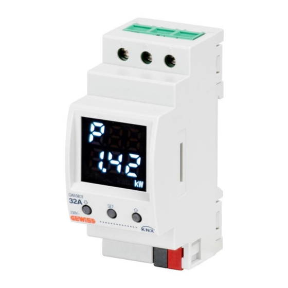
- Page 1 KNX single-phase energy meter with direct connection GWA9801 Technical Manual...
-
Page 2: Table Of Contents
Contents Introduction ..............................4 Application..............................4 Association limits ........................4 "Information” menu ............................. 5 “Energy meter settings” menu........................6 Parameters ..........................6 4.1.1 Delay time from power on and first transmission ..............6 “Electric measures” menu .......................... 8 Parameters ..........................9 5.1.1 Electric measures sending at bus restoring ................ - Page 3 6.2.11 Overflow value ........................25 6.2.12 Period counter sending condition ..................26 6.2.13 Period counter variation for sending..................27 6.2.14 Counter sending period (minutes) ..................27 6.2.15 Over power threshold number counter format ..............27 6.2.16 Overflow value ........................27 6.2.17 Number counter sending condition ..................
-
Page 4: Introduction
1 Introduction The device acts as a power meter. It has a built-in meter for measuring the following electric values and sending them on the BUS: active energy consumed and produced, active/reactive/apparent power, RMS voltage, RMS current, power frequency and factor. -
Page 5: "Information" Menu
3 "Information” menu The Information menu reminds the user, in operating terms, how to access the PROG menu in order to activate the programming mode of the physical or individual address of the device, and how to return from this menu to the RUN menu (long press on the UP and DOWN push-buttons). -
Page 6: "Energy Meter Settings" Menu
4 “Energy meter settings” menu The Energy meter settings menu contains just one parameter for configuring the transmission of telegrams on the BUS following a BUS voltage failure and reset, to avoid a surge in messages and the risk of them colliding. - Page 7 If the values 11..21 seconds (depends on physical address) and 5..9 seconds (depends on physical address) are set, the device automatically calculates the transmission delay using an algorithm that examines the physical address of the device itself; the values indicated (11/21 or 5/9) indicate the minimum and maximum limits of the value range that can be calculated.
-
Page 8: "Electric Measures" Menu
5 “Electric measures” menu The Electric measures menu contains the parameters for enabling and setting the conditions for sending the electric measurements detected for the load connected to the device. This menu is always visible. The structure of the menu is as follows: Fig. -
Page 9: Parameters
Press SET again to reset the counter, or press the arrow push-buttons (or wait for the inactivity time- out) to annul the reset. The following parameters are used to configure the ways of measuring and sending the various values. 5.1 Parameters 5.1.1 Electric measures sending at bus restoring The “Electric measures sending at bus restoring”... -
Page 10: Consumed Energy Counter Format
enable primary and differential counters If enable primary counter is selected, the “Consumed energy counter format”, “Consumed energy primary counter init value”, “Reinitialize consumed energy counters”, and “Consumed energy primary counter sending condition” parameters are displayed, along with the Consumed active energy primary counter communication object. -
Page 11: Consumed Energy Primary Counter Sending Condition
5.1.6 Consumed energy primary counter sending condition The “Consumed energy primary counter sending condition” parameter defines the conditions for sending the current primary counter value. The values that can be set are: sending on request sending on variation (default value) sending periodically sending on variation and periodically Selecting sending on variation or sending on variation and periodically, visualises the parameter... -
Page 12: Consumed Energy Differential Counter Overflow Value
5.1.10 Consumed energy differential counter overflow value The “Consumed energy differential counter overflow value” parameter is used to set the maximum value of the differential active energy counter; in fact, unlike the primary counter, it is possible to set the maximum count value - i.e. -
Page 13: Consumed Energy Differential Counter Sending Period (Minutes)
5.1.13 Consumed energy differential counter sending period (minutes) The “Consumed energy differential counter sending period (minutes)” parameter is visible if the differential counter value is sent periodically. It defines the frequency for spontaneously sending telegrams indicating the current differential counter value. The values that can be set are: from 1 to 255 in steps of 1 (default value 15) In the event of a supply voltage failure, the differential counter value is saved in a non-volatile memory so it can be reset when the power supply returns. -
Page 14: Produced Energy Counter Format
energy differential counter sending condition” parameters and the Produced active energy differential counter communication object. 5.1.16 Produced energy counter format The capacity of the primary and differential counters used for the energy count must be sufficient to measure the energy in KNX coding in kWh (maximum value = 2147483647 kWh). The “Produced energy counter format”... -
Page 15: Produced Primary Counter Energy Variation For Sending
sending on variation and periodically Selecting sending on variation or sending on variation and periodically visualises the “Produced primary counter energy variation for sending” parameter, whereas selecting sending periodically or sending on variation and periodically visualises the “Produced energy primary counter sending period (minutes)” parameter. -
Page 16: Produced Energy Differential Counter Sending Condition
If the format is watthour (Wh), the format (Data Point Type) of the Produced active energy differential counter communication object is 13.010 DPT_ActiveEnergy, and the values that can be set for the parameter are: from 0 to 2147483647 (default value) watthour, in steps of 1 ... -
Page 17: Start/Stop Produced Energy Differential Counter From Bus
In the event of a supply voltage failure, the differential counter value is saved in a non-volatile memory so it can be reset when the power supply returns. 5.1.26 Start/stop produced energy differential counter from bus Unlike the primary counter, the differential counter can be started/stopped via a BUS command; this makes it possible, for example, to measure the energy produced within a specific time band managed by another KNX device. -
Page 18: Transmission Of The Power Values
10 (W/VA/VAR) 20 (W/VA/VAR) 50 (W/VA/VAR) (default value) 100 (W/VA/VAR) PARAMETERS RELATING TO “POWER FACTOR” 5.1.29 Transmission of the power values The device can signal the current value of the power factor of the input signal detected on the contacts, using the Power factor measured (Data Point Type 14.057 DPT_Value_Power_Factor) communication object. -
Page 19: Current Rms Value Sending
10 Volt 15 Volt 25 Volt PARAMETERS RELATING TO “RMS CURRENT” 5.1.33 Current RMS value sending The device can signal the current value of the current absorbed by the load connected to the channel contacts, using the Current RMS measured (Data Point Type 9.021 DPT_Value_Curr) communication object. The conditions that determine the sending of the communication object that signals the absorbed current can be set via the “Current RMS value sending”... - Page 20 1 Hertz 2 Hertz 5 Hertz (default value) 10 Hertz...
-
Page 21: "Power Thresholds" Menu
6 “Power thresholds” menu Up to 20 absorption limit thresholds can be set and monitored; when one of the thresholds is exceeded, the device calculates how long the limit power remained above the threshold or how often it exceeded the limit. The sub-menus for each of the 5 thresholds are made visible according to how the “Power thresholds number to activate”... -
Page 22: Power Thresholds X Menu Parameters
For all the thresholds selected, the configuration menus of the parameters (and the corresponding objects) relating to each one will appear. The Power threshold x enable (Data Point Type:1.002 DPT_Bool) and Power threshold x enable status (Data Point Type:1.003 DPT_Enable) communication objects are used respectively to receive the threshold activation commands and send the signals regarding the threshold activation status;... -
Page 23: Power Threshold Initial Value (W)
To activate or deactivate the power threshold directly on the device (from the page showing the status of the corresponding threshold), press the SET/MODE push-button several times until the required option is displayed. Power threshold N Power threshold N enabled disabled When the power threshold is exceeded, the... -
Page 24: Changing Threshold Setting
Note that, in the case of a negative threshold value, the limit is considered “exceeded” when the measured power value is lower than the “Limit threshold” value; when the power value rises below the “Limit threshold - hysteresis” value, the limit is considered “not exceeded”. If this rule is not respected after ETS download, the default values are used. -
Page 25: At Overcoming Power Threshold
6.2.7 At overcoming power threshold The “At overcoming power threshold” parameter is used to set the value to be sent when the defined limit is exceeded. The values that can be set are no action send “0” send “1” (default value) 6.2.8 At coming back under power threshold The “At coming back under power threshold”... -
Page 26: Period Counter Sending Condition
Depending on the value set for the “Over power threshold period counter format” parameter, the values that can be set for this item will be different: If the counter format is 4 byte (seconds), the Period counter over power threshold x (s) (Data Point Type: 13.100 DPT_LongDeltaTimeSec) communication object is visible and the values that can be set for the above parameter are: from 0 to 2147483647 (default value ≈... -
Page 27: Period Counter Variation For Sending
6.2.13 Period counter variation for sending The “Period counter variation for sending” parameter is visible if the "period above threshold" counter value is sent on variation. It defines the minimum count variation (in relation to the last value sent) that causes the new value to be spontaneously sent. -
Page 28: Number Counter Sending Condition
Via the Overflow Number counter over power threshold x (Data Point Type: 1.002 DPT_Bool) object to indicate the overflow of the "exceeded absorption limit threshold number" counter. When an overflow occurs, a value of “1” is sent; a value of “0” is sent when the counter is reinitialised. The device can use the Reset Number counter over power threshold x (Data Point Type: 1.015 DPT_Reset) communication object to receive the counter reinitialisation command that brings the count back to its initial value of 0. -
Page 29: Power Threshold Function At Bus Restoring
deactive active (default value) 6.2.21 Power threshold function at bus restoring The “Power threshold function at bus restoring” parameter enables the power threshold function following a BUS voltage reset. The possible values are: deactive active as before voltage dropping (default value) With deactive, the power threshold function is not activated when the BUS voltage is reset. -
Page 30: Annex
7 Annex The following notes may be useful for understanding how to access certain configuration menus of the GWA9801 device, using the push-buttons on the device itself and the relative information on the display. 7.1 Local menu and push-buttons on the GWA9801 The device has the 3 multi-function push-buttons shown below: ... -
Page 31: Accessing The Prog Status Menu And The Firmware Version
The following paragraph explains how to access PROG status in order to program the physical (or individual) KNX address. To use the device push-buttons to access the menus for the RUN and SET statuses, and the relative info on the display, refer to the Programming Manual and the Installation Manual. 7.2 Accessing the PROG status menu and the Firmware Version The physical KNX address can only be programmed by accessing the relative “PROG status”... -
Page 32: Device Start-Up Procedure
Note that the same message - “Pr.L On” - that indicates the activation of the physical address programming mode also appears on the display when the mode is activated via the BUS with a specific telegram sent by the ETS application (device LED - ON). In the same way (and in keeping with normal manual management), the deactivation of the mode via the BUS (device LED - OFF) will take you back to the previous message - “Pr.L OFF”... -
Page 33: Procedure For Activating The Physical Address Programming Mode
7.3.2 Procedure for activating the physical address programming mode If the device has no physical address configured, the physical address programming launch screen will be displayed after the visualisation of the firmware version. This page is used to activate/deactivate the programming mode for the physical address of the KNX device. -
Page 34: Feedback Of Application Deletion By Ets
7.6 Feedback of application deletion by ETS During the deletion of the application program (or application) by ETS, the message “EtS dL” will appear on the screen and will remain if the device is not relaunched at the end of the procedure. In this status, the normal download of the application from ETS can be resumed without relaunching the device as long as the physical address has not been deleted as well. -
Page 35: Communication Objects
8 Communication objects The communication objects are listed in the following table: Output objects: DATAPOINT OBJECT NAME FUNCTION DESCRIPTION TYPE 13.010 Value Indicates the current value of the primary DPT_ActiveEnerg Consumed active energy primary counter watthour [Wh] counter for active consumed energy Value 13.013 kilowatthour... - Page 36 14.033 Value in Hertz Indicates the current value of the mains DPT_Value_Freq Frequency measured [Hz] frequency uency Indicates the activation status of the load 1.003 Active/Deactive Power threshold x absorption limit threshold DPT_Enable … 232 enable status 14.056 Value in Watt Indicates the current value of the load DPT_Value_Pow Power threshold x...
- Page 37 1=Reset / 0=No Receives the counter value reset Reset period counter over power 1.015 DPT_Reset action command 40 51 62 73 … threshold X 1=Reset / 0=No Receives the counter value reset Reset number counter over power 1.015 DPT_Reset action command 43 54 65 76 …...
Need help?
Do you have a question about the GHORUS GWA9801 and is the answer not in the manual?
Questions and answers