Advertisement
Quick Links
Index
MOULDED CASE CIRCUIT BREAKERS MSX
General technical data
Time/Current characteristics
Compact MCCBs - MSXc
Traditional MCCBs - MSX
Electronic MCCBs - MSXE
MCCBs with residual current protection - MSXD
Accessories (auxiliary contacts, releases, motor operator, rotary handles and interlock)
Compact MCCBs - MSXc
Traditional MCCBs (MSX), electronic MCCBs (MSXE), MCCBs with RCD (MSXD)
Automatic transfer switch
Connections and temperature ratings
Compact MCCBs - MSXc
Traditional MCCBs (MSX), electronic MCCBs (MSXE), MCCBs with RCD (MSXD)
Dimension
Circuit breakers (fixed and plug-in version/with and without motor operator)
Direct and transmitted rotary handles
Terminal covers and interpole barriers
Link and wire mechanical interlocks
For technical information contact the Technical Assistance Service or visit gewiss.com
Technical Information
page 2
page 7
page 12
page 21
page 37
page 41
page 50
page 68
page 77
page 82
page 90
page 148
page 157
page 163
Version 2.0
1
Advertisement

Related Manuals for Gewiss MSX 160c


Summary of Contents for Gewiss MSX 160c
- Page 1 Circuit breakers (fixed and plug-in version/with and without motor operator) page 90 Direct and transmitted rotary handles page 148 Terminal covers and interpole barriers page 157 Link and wire mechanical interlocks page 163 For technical information contact the Technical Assistance Service or visit gewiss.com Technical Information Version 2.0...
- Page 2 0.8 / 1 1.5 / 1.9 1.1 / 1.4 1.5 / 1.9 2.3 / 3.1 Key: •supplied as standard max 225A • optional max 536a -not available For technical information contact the Technical Assistance Service or visit gewiss.com Technical Information Version 2.0...
- Page 3 4.3 / 5.7 (MSXE 400) 4.3 / 5.6 9.1 / 12.3 11 / 14.8 19.8 / 25 27 / 35 5 / 6.5 (MSXE 630) For technical information contact the Technical Assistance Service or visit gewiss.com Technical Information Version 2.0...
- Page 4 Weight (3P / 4P) (kg) 0.7 / 0.9 1.5 / 1.9 4.4 / 5.8 (MSXM 630) Key: •supplied as standard max 536A • optional -not available For technical information contact the Technical Assistance Service or visit gewiss.com Technical Information Version 2.0...
- Page 5 -20 +60 45%÷85% 45%÷85% 45%÷85% 210 / 280 210 / 280 210 / 280 8.5 / 11.5 10.4 / 14 18.2 / 23.4 24.9 / 32.9 For technical information contact the Technical Assistance Service or visit gewiss.com Technical Information Version 2.0...
- Page 6 45%÷85% 45%÷85% Width (3P / 4P) (mm) Dimensions Height (mm) Depth (mm) Weight (3P / 4P) (kg) Key: •supplied as standard • optional -not available For technical information contact the Technical Assistance Service or visit gewiss.com Technical Information Version 2.0...
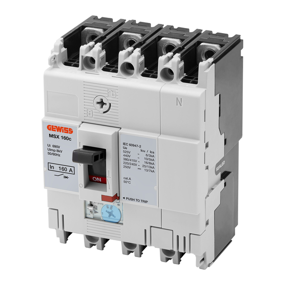
- Page 7 160A MCCBs are extremely compact in size (W75 H130 D68) and offer space saving solutions for electrical power distribution where the installation size is critical. 160A models have adjustable thermal and fixed magnetic settings. 250A MCCBs have adjustable thermal and adjustable magnetic settings. For technical information contact the Technical Assistance Service or visit gewiss.com Technical Information...
- Page 8 16 kA 5 - 11 x In MSX 250c 5 - 13 x In 25 kA 5 - 11 x In Magnetic trip tolerance +/-20% For technical information contact the Technical Assistance Service or visit gewiss.com Technical Information Version 2.0...
- Page 9 MSX 250c (250A) 250A Max 250A Min Magnetic trip Magnetic trip settings settings 880% - 1320% 400% - 600% Pe rc en t Ra t ed Current For technical information contact the Technical Assistance Service or visit gewiss.com Technical Information Version 2.0...
- Page 10 MSX 250c at 400/415V AC MSX 250c at 440V AC 1000 1000 1000 1000 Prospective short-circuit current in RMS sym. (kA) Prospective short-circuit current in RMS sym. (kA) For technical information contact the Technical Assistance Service or visit gewiss.com Technical Information Version 2.0...
- Page 11 MSX 250c at 400/415V AC MSX 250c at 440V AC 0.05 0.03 0.02 0.01 1000 Prospective short circuit current in RMS sym.(kA) Prospective short-circuit current in RMS sym. (kA) For technical information contact the Technical Assistance Service or visit gewiss.com Technical Information Version 2.0...
- Page 12 Lowering the short-circuit tripping threshold can allow a higher earth-loop impedance in an installation and provide end-of-cable protection with the correct disconnection times. For technical information contact the Technical Assistance Service or visit gewiss.com Technical Information Version 2.0...
- Page 13 MCCBs without thermal protection elements are available for this application. Four pole MCCBs with magnetic trip only have protection on the neutral pole as standard. For technical information contact the Technical Assistance Service or visit gewiss.com Technical Information...
- Page 14 P e r c e n t R a te d C u r r e n t P e r ce n t Ra t e d C u r re n t For technical information contact the Technical Assistance Service or visit gewiss.com Technical Information...
- Page 15 P e r c e n t R a te d C u r r e n t P e r c e nt Ra te d C ur r e nt For technical information contact the Technical Assistance Service or visit gewiss.com Technical Information...
- Page 16 Magnetic trip current Adjustable setting range of magnetic trip P e r ce n t R a te d C u r r e n t For technical information contact the Technical Assistance Service or visit gewiss.com Technical Information Version 2.0...
- Page 17 MSX 160, MSX 250 at 400/415/440V AC MSX 160, MSX 250 at 690V AC 160-250A Prospective short circuit current in RMS sym. (kA) Prospective short circuit current in RMS sym. (kA) For technical information contact the Technical Assistance Service or visit gewiss.com Technical Information Version 2.0...
- Page 18 MSX 400 at 400/415/440V AC MSX 400 at 690V AC Prospective short circuit current in RMS sym. (kA) Prospective short circuit current in RMS sym. (kA) For technical information contact the Technical Assistance Service or visit gewiss.com Technical Information Version 2.0...
- Page 19 MSX 160, MSX 250 at 400/415/440V AC MSX 160, MSX 250 at 690V AC Prospective short circuit current in RMS sym. (kA) Prospective short circuit current in RMS sym. (kA) For technical information contact the Technical Assistance Service or visit gewiss.com Technical Information Version 2.0...
- Page 20 MSX 400 at 400/415/440V AC MSX 400 at 690V AC Prospective short circuit current in RMS sym. (kA) Prospective short circuit current in RMS sym. (kA) For technical information contact the Technical Assistance Service or visit gewiss.com Technical Information Version 2.0...
- Page 21 The ground fault trip function is available from 400A to 1600A. Neutral Protection (NP) Neutral protection (available only for 4P versions) can be adjusted at 100% or 50% from 400A frame to 1600A frame. For technical information contact the Technical Assistance Service or visit gewiss.com Technical Information Version 2.0...
- Page 22 ± 15% Ground Fault Trip (GF) Total clearing time +50ms, resettable time –20ms Neutral Protection (NP) Tripping when (I 1.05) < load current (I 1.3) For technical information contact the Technical Assistance Service or visit gewiss.com Technical Information Version 2.0...
- Page 23 0.9 or less. max. = 13 x I Characteristic of neutral protection (t vs. I ) is identical to characteristic of phase protection (t vs. I For technical information contact the Technical Assistance Service or visit gewiss.com Technical Information Version 2.0...
- Page 24 0.5 x I can be selected. Characteristic of neutral protection (t vs. I ) is identical to characteristic of phase protection (t vs. I For technical information contact the Technical Assistance Service or visit gewiss.com Technical Information Version 2.0...
- Page 25 0.5 x I can be selected. Characteristic of neutral protection (t vs. I ) is identical to characteristic of phase protection (t vs. I For technical information contact the Technical Assistance Service or visit gewiss.com Technical Information Version 2.0...
- Page 26 0.5 x I can be selected. Characteristic of neutral protection (t vs. I ) is identical to characteristic of phase protection (t vs. I For technical information contact the Technical Assistance Service or visit gewiss.com Technical Information Version 2.0...
- Page 27 0.5 x I can be selected. Characteristic of neutral protection (t vs. I ) is identical to characteristic of phase protection (t vs. I For technical information contact the Technical Assistance Service or visit gewiss.com Technical Information Version 2.0...
- Page 28 0.5 x I can be selected. Characteristic of neutral protection (t vs. I ) is identical to characteristic of phase protection (t vs. I For technical information contact the Technical Assistance Service or visit gewiss.com Technical Information Version 2.0...
- Page 29 0.5 x I can be selected. Characteristic of neutral protection (t vs. I ) is identical to characteristic of phase protection (t vs. I For technical information contact the Technical Assistance Service or visit gewiss.com Technical Information Version 2.0...
- Page 30 MSXE 400 at 400/415/440V AC MSXE 400 at 690V AC Prospective short circuit current in RMS sym. (kA) Prospective short circuit current in RMS sym. (kA) For technical information contact the Technical Assistance Service or visit gewiss.com Technical Information Version 2.0...
- Page 31 MSXE 1000 (800A) at 400/415/440V AC MSX 1000 (800A) at 690V AC Prospective short circuit current in RMS sym. (kA) Prospective short circuit current in RMS sym. (kA) For technical information contact the Technical Assistance Service or visit gewiss.com Technical Information Version 2.0...
- Page 32 MSXE 1250 at 400/415/440V AC MSX 1250 at 690V AC Prospective short circuit current in RMS sym. (kA) Prospective short circuit current in RMS sym. (kA) For technical information contact the Technical Assistance Service or visit gewiss.com Technical Information Version 2.0...
- Page 33 MSXE 160, MSXE 250 at 400/415/440V AC MSXE 160, MSXE 250 at 690V AC Prospective short-circuit current in RMS sym. (kA) Prospective short-circuit current in RMS sym. (kA) For technical information contact the Technical Assistance Service or visit gewiss.com Technical Information Version 2.0...
- Page 34 Prospective short-circuit current in RMS sym. (kA) MSXE 630 a 400/415/440V AC MSXE 630 a 690V AC Prospective short-circuit current in RMS sym. (kA) Prospective short-circuit current in RMS sym. (kA) For technical information contact the Technical Assistance Service or visit gewiss.com Technical Information Version 2.0...
- Page 35 MSXE 1000 (1000A) at 690V AC 0.05 0.05 0.03 0.03 0.02 0.02 Prospective short-circuit current in RMS sym. (kA) Prospective short-circuit current in RMS sym. (kA) For technical information contact the Technical Assistance Service or visit gewiss.com Technical Information Version 2.0...
- Page 36 Prospective short-circuit current in RMS sym. (kA) MSXE 1600 at 400/415/440V AC MSXE 1600 at 690V AC Prospective short-circuit current in RMS sym. (kA) Prospective short-circuit current in RMS sym. (kA) For technical information contact the Technical Assistance Service or visit gewiss.com Technical Information Version 2.0...
- Page 37 MSXD range is available in two frame sizes with interrupting capacities of 25kA and 36kA; the first size in available with rated current from 20A to 125A, the second size is available with rated current from 160A to 250A. Every size is offered with adjustable thermal and fixed magnetic protection characteristics. For technical information contact the Technical Assistance Service or visit gewiss.com Technical Information...
- Page 38 13 x In ∞ 36 kA 0.03, 0.1, 0.3, 0.5, 1, 3 0 (40), 60 (195), 200 (365), 400 (620), 700 (950), NT 10 x In For technical information contact the Technical Assistance Service or visit gewiss.com Technical Information Version 2.0...
- Page 39 160A Min 1040% - 1560% Magnetic trip settings 400% - 600% Pe rce n t R a te d Cu rre n t Percent Rated Current For technical information contact the Technical Assistance Service or visit gewiss.com Technical Information Version 2.0...
- Page 40 MSXD 125 at 400/415/440V AC MSXD 160, MSXD 250 at 400/415/440V AC Prospective short-circuit current in RMS sym. (kA) Prospective short-circuit current in RMS sym. (kA) For technical information contact the Technical Assistance Service or visit gewiss.com Technical Information Version 2.0...
- Page 41 SIGNALING AND CONTROL (INTERNAL ACCESSORIES) Electrical control accessories for MSX 160c and MSX 250c range are designed with the installer in mind. Auxiliary contacts of open/closed position, fault indicator switch, shunt trip and undervoltage releases are of modular design and convenient to use.
- Page 42 Type of breaker AC voltage (V) DC voltage (V) 200-240 MSX/M 160c MSX/M 250c NOTE: UV releases are installed on the right hand side of the breaker. For technical information contact the Technical Assistance Service or visit gewiss.com Technical Information Version 2.0...
- Page 43 The motor operator is of a short time duty. Do not subject it to more than 10 continuous ON-OFF operations. If this occurs, allow the motor operator to cool for at least 15 minutes. When the rated operational voltage is DC24V the open voltage will be DC22V. For technical information contact the Technical Assistance Service or visit gewiss.com Technical Information...
- Page 44 3. Use noise filters if the control power supply of the motor operator is shared by peripheral devices. Otherwise, power supply noise may cause malfunction of the peripheral devices. Control Circuit Diagrams of Motor Operators The “+” and “–” symbols indicate the polarities of DC-rated motor operators. For technical information contact the Technical Assistance Service or visit gewiss.com Technical Information Version 2.0...
- Page 45 This Mechanism allows the breaker to be padlock in the OFF position. Padlocks are not supplied. Up to three padlocks can be installed. Padlock dimensions (mm) Diameter 13 min Ø 5.5-8 For technical information contact the Technical Assistance Service or visit gewiss.com Technical Information Version 2.0...
- Page 46 Operating Direction of Handles Rotate the operating handle clockwise to turn the breaker on. Type 160A Frame Type 250A Frame Rotate clockwise to turn the breaker ON For technical information contact the Technical Assistance Service or visit gewiss.com Technical Information Version 2.0...
- Page 47 Toggle locking devices allow MCCB's to be locked ON or OFF using up to three padlocks. Locking devices for 160A and 250A frame models accept padlocks with a 5mm hasp diameter. For technical information contact the Technical Assistance Service or visit gewiss.com Technical Information...
- Page 48 Terminal Cover for Rear Connection Terminal cover lock option is available to lock and seal front and rear terminal covers on to MCCB. For technical information contact the Technical Assistance Service or visit gewiss.com Technical Information Version 2.0...
- Page 49 Additional interpole barriers can be ordered individually. All interpole barriers can easily be fitted to either end of an MCCB. MCCB fitted with Interpole Barriers at both ends For technical information contact the Technical Assistance Service or visit gewiss.com Technical Information...
- Page 50 • No tools are required for this, except a screwdriver to lift the MCCB front cover clips. • Accessories fit with a firm click when installed correctly. • Colour coding of accessories helps identification and installation. Per informazioni tecniche contattate il SAT o visitate il sito gewiss.com Informazioni Tecniche Versione 2.0...
- Page 51 • Undervoltage releases with time delays require an external time delay controller which clips to the side of the MCCB. * Shunt trip and undervoltage releases cannot be installed in this model. Per informazioni tecniche contattate il SAT o visitate il sito gewiss.com Informazioni Tecniche...
- Page 52 Rated value of voltage and current of auxiliary contacts Current (A) Current (A) Minimum Voltage (V) Voltage (V) Load Resistive Inductive Resistive Inductive Load Load Load Load 100mA at 0.05 15V DC. Per informazioni tecniche contattate il SAT o visitate il sito gewiss.com Informazioni Tecniche Versione 2.0...
-
Page 53: Table Of Contents
380-450 MSX 125 MSX/E 160 MSX/E 250 MSX/E/M 400 MSXE/M 630 Voltage AC Voltage DC MCCB Model 200-240 380-415 MSXE/M 1000 MSXE/M 1250 MSXE/M 1600 Per informazioni tecniche contattate il SAT o visitate il sito gewiss.com Informazioni Tecniche Versione 2.0... - Page 54 Up to 4 terminal blocks can be installed on a 125A, 160A or 250A frame MCCB. Up to 5 terminal blocks can be installed on a 400A to 800A frame MCCB. Terminal Block for Plug-in MCCBs Per informazioni tecniche contattate il SAT o visitate il sito gewiss.com Informazioni Tecniche...
-
Page 55: Voltage (V)
No tools are needed to fit the motor operator. 400A frame to 1000A frame motor operators are held in place with mounting screws. They can be installed easily in the field. Per informazioni tecniche contattate il SAT o visitate il sito gewiss.com Informazioni Tecniche... -
Page 56: Mccb Model
Note: Operating times shown in the above table apply only when the rated operational voltage is supplied to the motor operator. The voltage supplied to the motor operator must be within the range of 85% and 110% of the rated operating voltage. Per informazioni tecniche contattate il SAT o visitate il sito gewiss.com Informazioni Tecniche... - Page 57 When a mechanical interlock is used with motor operators, design the control circuit to provide electrical interlocking between the motor operators. The electrical interlocking should prevent a close signal being sent to a motor operator unless the other motor operator and circuit breaker are in the OFF position. Per informazioni tecniche contattate il SAT o visitate il sito gewiss.com Informazioni Tecniche...
-
Page 58: Mccb Model
Dielectric withstand voltage AC1500V The value in brackets for 24V DC (AC500V) Weight (kg) NOTE Maximum values at AC230V, 50Hz Maximum values at the rated operating voltages Per informazioni tecniche contattate il SAT o visitate il sito gewiss.com Informazioni Tecniche Versione 2.0... - Page 59 This automatic charge/discharge function is necessary to prepare the closing mechanism for the next ON/OFF operation. The sound of the charging or discharging of the spring should not be mistaken for a malfunction. Per informazioni tecniche contattate il SAT o visitate il sito gewiss.com Informazioni Tecniche...
- Page 60 This means that the positioning of the door cutouts is symmetrical for breakers mounted horizontally on either side of a vertical busbar system. MCCB ON MCCB ON Per informazioni tecniche contattate il SAT o visitate il sito gewiss.com Informazioni Tecniche Versione 2.0...
- Page 61 This mechanism allows the breaker to be padlocked in the OFF position. Metal lever available. Padlocks are not supplied. Up to three padlocks can be installed. Per informazioni tecniche contattate il SAT o visitate il sito gewiss.com Informazioni Tecniche Versione 2.0...
- Page 62 125A to 160A and 250A frame models accept padlocks with 5mm hasp diameter. Locking devices for 400A to 1600A frame models accept padlock with 8mm hasp diameter. Per informazioni tecniche contattate il SAT o visitate il sito gewiss.com Informazioni Tecniche Versione 2.0...
- Page 63 • Terminal covers have a megger measurement hole of 4mm diameter on each phase. Options • A terminal cover for 125A to 630A frame models include facility for an anti-tampering seal to be added. Per informazioni tecniche contattate il SAT o visitate il sito gewiss.com Informazioni Tecniche Versione 2.0...
- Page 64 Terminal covers for rear connection are available for 125A to 1000A frame models and may be used on MCCBs fitted with rear connections (RC) or plug-in connections. They prevent access to the terminals from the front and top. Terminal Covers for Rear Connection Per informazioni tecniche contattate il SAT o visitate il sito gewiss.com Informazioni Tecniche Versione 2.0...
- Page 65 MCCB have been designed to accept an additional interpole barrier between two adjacent MCCBs. MCCB Fitted with Interpole Barriers Interpole Barriers between Adjacent MCCBs on Both Ends Per informazioni tecniche contattate il SAT o visitate il sito gewiss.com Informazioni Tecniche Versione 2.0...
- Page 66 The electrical control system of an automatic changeover scheme which uses these interlocks should not attempt to switch the MCCBs to a combination indicated as "NOT ALLOWED" in the above table otherwise damage to the motor operations will occur. Per informazioni tecniche contattate il SAT o visitate il sito gewiss.com Informazioni Tecniche...
- Page 67 The electrical control system of an automatic changeover scheme which uses these interlocks should not attempt to switch the MCCBs to a combination indicated as "NOT ALLOWED" in the above table otherwise damage to the motor operations will occur. Per informazioni tecniche contattate il SAT o visitate il sito gewiss.com Informazioni Tecniche...
- Page 68 • 6 configurable DC outputs • Power and energy monitoring (kW, kWh, kVAr, kVAh, kVArh) • Event log • Auto start inhibit • Load inhibition Per informazioni tecniche contattate il SAT o visitate il sito gewiss.com Informazioni Tecniche Versione 2.0...
- Page 69 Maximum common mode offset 70V (on-board protection via surge arrester) Maximum distance 1.2km Generator STATUS Mains STATUS START STATUS ON/OFF Schematic Diagram: Automatic Changeover System with Interlocked MCCBs Per informazioni tecniche contattate il SAT o visitate il sito gewiss.com Informazioni Tecniche Versione 2.0...
- Page 70 External fuses are recommended to protect the power supply input connection cables Dimensions overall 136mm x 140mm x 63mm Weight 0.5 kg Section of connection cable 0,6÷1,5 mm Rated tightening torque 0,8 Nm Operating temperature -30°C...+60°C Per informazioni tecniche contattate il SAT o visitate il sito gewiss.com Informazioni Tecniche Versione 2.0...
- Page 71 Fuses holder 3P+N 10,3X38 690VAC 32A GWD6725 Contactor 40A 2NO+2NC 230V GW74411 Fixed key selector 0-1 GW74504 Contact 1 N.O. - 1 N.C. 10A 250V Per informazioni tecniche contattate il SAT o visitate il sito gewiss.com Informazioni Tecniche Versione 2.0...
- Page 72 Fuses holder 3P+N 10,3X38 690VAC 32A GWD6725 Contactor 40A 2NO+2NC 230V GW74411 Fixed key selector 0-1 GW74504 Contact 1 N.O. - 1 N.C. 10A 250V Per informazioni tecniche contattate il SAT o visitate il sito gewiss.com Informazioni Tecniche Versione 2.0...
- Page 73 Fuses holder 3P+N 10,3X38 690VAC 32A GWD6725 Contactor 40A 2NO+2NC 230V GW74411 Fixed key selector 0-1 GW74504 Contact 1 N.O. - 1 N.C. 10A 250V Per informazioni tecniche contattate il SAT o visitate il sito gewiss.com Informazioni Tecniche Versione 2.0...
- Page 74 Fuses holder 3P+N 10,3X38 690VAC 32A GWD6725 Contactor 40A 2NO+2NC 230V GW74411 Fixed key selector 0-1 GW74504 Contact 1 N.O. - 1 N.C. 10A 250V Per informazioni tecniche contattate il SAT o visitate il sito gewiss.com Informazioni Tecniche Versione 2.0...
- Page 75 Fuses holder 3P+N 10,3X38 690VAC 32A GWD6725 Contactor 40A 2NO+2NC 230V GW74411 Fixed key selector 0-1 GW74504 Contact 1 N.O. - 1 N.C. 10A 250V Per informazioni tecniche contattate il SAT o visitate il sito gewiss.com Informazioni Tecniche Versione 2.0...
- Page 76 Fuses holder 3P+N 10,3X38 690VAC 32A GWD6725 Contactor 40A 2NO+2NC 230V GW74411 Fixed key selector 0-1 GW74504 Contact 1 N.O. - 1 N.C. 10A 250V Per informazioni tecniche contattate il SAT o visitate il sito gewiss.com Informazioni Tecniche Versione 2.0...
- Page 77 11.8~18.6 7.8~11.8 11.8~18.6 Hex head Hex head Hex head Hex head Hex head MSX/M 250c M8x18 M8x18 M10x25 M6x18 M8x25 7.8~12.7 7.8~12.7 22.5~37.2 7.8~11.8 11.8~18.6 For technical information contact the Technical Assistance Service or visit gewiss.com Technical Information Version 2.0...
- Page 78 Maximum dimensions of crimp lug Frame Size (A) Width, W (mm) 17.2 Diameter, d (mm) Maximum from centre to tip, e(mm) For technical information contact the Technical Assistance Service or visit gewiss.com Technical Information Version 2.0...
- Page 79 B2 Distance from end face of breaker to insulation plate. C Gap between breakers. D Distance from side of breaker to side plate (earthed metal). E Dimension of insulation over exposed conductors. For technical information contact the Technical Assistance Service or visit gewiss.com Technical Information Version 2.0...
- Page 80 The breakers are available for normal connection by default. Reverse connection is optional. See tables below. Line side Load side Load side Line side Normal Reverse connection connection For technical information contact the Technical Assistance Service or visit gewiss.com Technical Information Version 2.0...
- Page 81 160A MSX/M 250c Front Rear 250A Note: Supplied with terminal bars fitted as standard. Temperature ratings are not valid if the terminal bars are removed. For technical information contact the Technical Assistance Service or visit gewiss.com Technical Information Version 2.0...
- Page 82 The MSX/D 125, MSX/D 160 and MSX/D 250 models can be mounted on 35mm DIN rail along side the modular devices by means of a fixing bracket. In addition, 45mm high window panels can be used. The MSXE 160 and MSXE 250 models cannot be installed on DIN rail. 45mm For technical information contact the Technical Assistance Service or visit gewiss.com Technical Information Version 2.0...
- Page 83 Extended or spread front terminals FB are an extension of front terminal FC which can be fitted to line or load side terminals of circuit breaker. They are used to connect multiple conductors or large conductors. For technical information contact the Technical Assistance Service or visit gewiss.com Technical Information Version 2.0...
- Page 84 The rear terminal can be rotated in steps of 45 degrees on a 125A to 630A frame MCCBs and 90 degrees on a 800A and 1250A frame MCCBs. For technical information contact the Technical Assistance Service or visit gewiss.com Technical Information...
- Page 85 Connection bars are mounted for top access at mounted for rear access. supplied as standard and must be fitted. the top and rear access at the bottom. For technical information contact the Technical Assistance Service or visit gewiss.com Technical Information Version 2.0...
- Page 86 B2. Distance from end face of breaker to insulation plate C. Gap between breakers D. Distance from side of breaker to side panel (earthed metal) E. Dimensions of insulation over exposed conductors For technical information contact the Technical Assistance Service or visit gewiss.com Technical Information Version 2.0...
- Page 87 Take care that arc gases are emitted to both line and load sides. If using extension bars (optional), ensure the insulation distance for the application. For technical information contact the Technical Assistance Service or visit gewiss.com Technical Information Version 2.0...
- Page 88 MSX MCCBs may be mounted at any angle without affecting performance. Mounting angle does not affect performance. Direction of Power Supply Power can be supplied through MSX MCCBs in either direction without loss of performance. For technical information contact the Technical Assistance Service or visit gewiss.com Technical Information Version 2.0...
- Page 89 1600 1600 1520 1440 1280 1008 Note: Supplied with terminal bars fitted as standard. Temperature ratings are not valid if the terminal bars are removed. For technical information contact the Technical Assistance Service or visit gewiss.com Technical Information Version 2.0...
- Page 90 10.5 Front extended and spread terminals FB 25 25 25 25 25 ø 8.3 ø 8.3 : Handle Centre Line : Handle Frame Centre Line For technical information contact the Technical Assistance Service or visit gewiss.com Technical Information Version 2.0...
- Page 91 M4 0.7 Tapped hole M4 0.7 25 25 25 Tapped hole Panel cutout dimensions shown give an allowance of 1.0mm or more around the handle escutcheon. For technical information contact the Technical Assistance Service or visit gewiss.com Technical Information Version 2.0...
- Page 92 Interpole barrier 25(max.) (removable) max.t7 Conductor Conductor overlap, max overlap, max 48.5 48.5 48.5 ø11 ø11 : Handle Centre Line : Handle Frame Centre Line For technical information contact the Technical Assistance Service or visit gewiss.com Technical Information Version 2.0...
- Page 93 52.5 52.5 M4 0.7 53.5 53.5 M4 0.7 Tapped Tapped hole hole Panel cutout dimensions shown give an allowance of 1.0mm around the handle escutcheon. For technical information contact the Technical Assistance Service or visit gewiss.com Technical Information Version 2.0...
- Page 94 Preparation of conductor Interpole barrier Mounting hole (removable) M8 screw Mounting screw Front extended terminals FB : Handle Centre Line : Handle Frame Centre Line For technical information contact the Technical Assistance Service or visit gewiss.com Technical Information Version 2.0...
- Page 95 DRILLIN PLAN Panel cutout (Front view) Tapped hole Tapped hole Panel cutout dimensions shown give an allowance of 1.0mm or more around the handle escutcheon. For technical information contact the Technical Assistance Service or visit gewiss.com Technical Information Version 2.0...
- Page 96 21.5 plug Mounting screw 30 30 30 164.5 28(max.) Preparation of conductor ø9 17(max.) max.t5 PANEL HINGE POSITION Panel hinge position (hatching area) bottom view For technical information contact the Technical Assistance Service or visit gewiss.com Technical Information Version 2.0...
- Page 97 DRILLIN PLAN Panel cutout (Front view) M4x0.7 ø18 Tapped hole M4X0.7 Tapped hole Panel cutout dimensions shown give an allowance of 1.5mm around the handle escutcheon. For technical information contact the Technical Assistance Service or visit gewiss.com Technical Information Version 2.0...
- Page 98 Support or rail Mounting screw TERMINATION OF BUSBAR Preperation of conductor (max.) Mounting screw M6x14 max. (max.) (max.) : Handle Centre Line : Handle Frame Centre Line For technical information contact the Technical Assistance Service or visit gewiss.com Technical Information Version 2.0...
- Page 99 Support or rail Mounting screw Drilling plan (front view) Detail of connecting part Oriented for rear access 14.2 14.2 22.2 22.2 4- 6 4- 6 17.5 22.5 For technical information contact the Technical Assistance Service or visit gewiss.com Technical Information Version 2.0...
- Page 100 30 30 30 27 22.2 Drilling plan (front view) Detail of connecting part Oriented for rear access 2- 6 4- 6 14.2 14.2 22.2 22.2 For technical information contact the Technical Assistance Service or visit gewiss.com Technical Information Version 2.0...
- Page 101 Oriented for front access 3.2t 21.8 2- 6 4- 6 Note that the insulation plate (supplied as standard) must be fitted between the base and the backplate. For technical information contact the Technical Assistance Service or visit gewiss.com Technical Information Version 2.0...
- Page 102 Interpole barrier (removable) Mounting hole M8 screw Mounting screw Front extended terminals FB Conductor overlap max. : Handle Centre Line : Handle Frame Centre Line For technical information contact the Technical Assistance Service or visit gewiss.com Technical Information Version 2.0...
- Page 103 PANEL CUTOUT DRILLIN PLAN (Front view) Tapped hole Tapped hole Panel cutout dimensions shown give an allowance of 1.0mm or more around the handle escutcheon. For technical information contact the Technical Assistance Service or visit gewiss.com Technical Information Version 2.0...
- Page 104 Interpole barrier Preparation of Mounting hole (removable) conductor Front panel t2 M8 screw Operating knob Mounting screw Connector plug PANEL HINGE POSITION (hatching area) bottomview For technical information contact the Technical Assistance Service or visit gewiss.com Technical Information Version 2.0...
- Page 105 Mounting screw PANEL CUTOUT DRILLIN PLAN (Front view) Tapped Tapped hole hole Panel cutout dimensions shown give an allowance of 1.5mm around the handle escutcheon. For technical information contact the Technical Assistance Service or visit gewiss.com Technical Information Version 2.0...
- Page 106 Mounting screw TERMINATION OF BUSBAR Preperation of conductor 15.5 (max.) Mounting screw M8x18 max. (max.) (max.) : Handle Centre Line : Handle Frame Centre Line For technical information contact the Technical Assistance Service or visit gewiss.com Technical Information Version 2.0...
- Page 107 Support or rail Mounting screw Drilling plan(front view) Detail of connecting part Oriented for rear access Terminal bars should be connected altemately on adjacent poles. For technical information contact the Technical Assistance Service or visit gewiss.com Technical Information Version 2.0...
- Page 108 Mounting screw M5x20 (61) Drilling plan (front view) Detail of connecting part Oriented for rear access Terminal bars should be connected alternately on adjacent poles. For technical information contact the Technical Assistance Service or visit gewiss.com Technical Information Version 2.0...
- Page 109 Mounting Plate Insulating plate Mounting screw M5 NUT (61) Mounting plate Insulating plate Drilling plan (front view) Detail of connecting part Oriented for front access For technical information contact the Technical Assistance Service or visit gewiss.com Technical Information Version 2.0...
- Page 110 (removable) Mounting hole Preparation of conductor M8 screw Mounting screw Front extended terminals FB Mounting screw : Handle Centre Line : Handle Frame Centre Line For technical information contact the Technical Assistance Service or visit gewiss.com Technical Information Version 2.0...
- Page 111 DRILLIN PLAN (front view) (front view) Tapped hole Tapped hole Panel cutout dimensions shown give an allowance of 1.0mm or more around the handle escutcheon. For technical information contact the Technical Assistance Service or visit gewiss.com Technical Information Version 2.0...
- Page 112 Preparation of conductor Interpole barrier (removable) Mounting Front panel t2 hole M8 Screw Operating knob Mounting screw Connector plug PANEL HINGE POSITION (hatching area) bottom view For technical information contact the Technical Assistance Service or visit gewiss.com Technical Information Version 2.0...
- Page 113 PANEL CUTOUT DRILLIN PLAN (front view) (front view) Tapped hole Tapped hole Panel cutout dimensions shown give an allowance of 1.5mm around the handle escutcheon. For technical information contact the Technical Assistance Service or visit gewiss.com Technical Information Version 2.0...
- Page 114 Mounting screw TERMINATION OF BUSBAR Preperation of conductor 15.5 (max.) Mounting screw M8x18 max. (max.) (max.) : Handle Centre Line : Handle Frame Centre Line For technical information contact the Technical Assistance Service or visit gewiss.com Technical Information Version 2.0...
- Page 115 Support or rail Mounting screw Drilling plan (front view) Drilling plan (front view) Oriented for rear access Terminal bars should be connected altemately on adjacent poles For technical information contact the Technical Assistance Service or visit gewiss.com Technical Information Version 2.0...
- Page 116 76.5 Mounting screw M5x20 Drilling plan (front view) Detail of connecting part Oriented for rear access Terminal bars should be connected alternately on adjacent poles For technical information contact the Technical Assistance Service or visit gewiss.com Technical Information Version 2.0...
- Page 117 (rear view) Mounting Plate Insulating plate Mounting screw M5 NUT Mounting plate Insulating plate Drilling plan (front view) Detail of connecting part Oriented for front access For technical information contact the Technical Assistance Service or visit gewiss.com Technical Information Version 2.0...
- Page 118 Mounting screw (With handle cap) Front extended and spread terminals FB 400A 630A Trip button (red) : Handle Centre Line : Handle Frame Centre Line For technical information contact the Technical Assistance Service or visit gewiss.com Technical Information Version 2.0...
- Page 119 630A PANEL CUTOUT DRILLIN PLAN (frontview) (front view) Tapped hole Tapped hole Panel cutout dimensions shown give an allowance of 1.0mm around the handle escutcheon. For technical information contact the Technical Assistance Service or visit gewiss.com Technical Information Version 2.0...
- Page 120 Manual operating On side 35 handle (removable) Manual operating handle (removable) M10 Screw Mounting screw Mounting screw Padlock Padlock PANEL HINGE POSITION hatching area bottom view For technical information contact the Technical Assistance Service or visit gewiss.com Technical Information Version 2.0...
- Page 121 (optional) 400A 630A Panel Panel PANEL CUTOUT DRILLIN PLAN (front view) (front view) Panel cutout dimensions shown give an allowance of 1.5mm around motor operator For technical information contact the Technical Assistance Service or visit gewiss.com Technical Information Version 2.0...
- Page 122 Mounting plate Manual operting handle (removable) Connector plug 400A 630A Drilling pian (front view) Tapped hole : Handle Centre Line : Handle Frame Centre Line For technical information contact the Technical Assistance Service or visit gewiss.com Technical Information Version 2.0...
- Page 123 Support or rail TERMINATION OF BUSBAR Preperation of conductor (max.) Mounting screw M10x30 max. (max.) (max.) : Handle Centre Line : Handle Frame Centre Line For technical information contact the Technical Assistance Service or visit gewiss.com Technical Information Version 2.0...
- Page 124 MOUNTING ON A SUPPORT OR RAILS Support or rail Mounting Mounting Angle Angle Detail of connecting part Oriented far rear access Terminal bars should be connected alternately on adjacent poles. For technical information contact the Technical Assistance Service or visit gewiss.com Technical Information Version 2.0...
- Page 125 Mounting screw M5 x 20 Drilling plan (front view) Detail of connecting part Oriented far rear access Teminal bars should be connected alternately on adjacent poles. For technical information contact the Technical Assistance Service or visit gewiss.com Technical Information Version 2.0...
- Page 126 Mounting plate Mounting screw M6x70 Mounting Plate Mounting M6 NUT Insulating Plate Insulating Plate Detail of connecting part Drilling plan Oriented far front access (front view) For technical information contact the Technical Assistance Service or visit gewiss.com Technical Information Version 2.0...
- Page 127 Trip button (red) 28 13 Mounting screw Conductor overlap, max 127.5 80.5 DRILLING PLAN (front view) Tapped hole : Handle Centre Line : Handle Frame Centre Line For technical information contact the Technical Assistance Service or visit gewiss.com Technical Information Version 2.0...
- Page 128 ELECTRONIC MCCB AND SWITCH DISCONNECTORS MSXE 1000 (800A), MSXM 1000 (800A) fixed version FRONT TERMINALS FC Toggle extension (removable) Trip button 28 13 (red) Mounting screw 127.5 80.5 For technical information contact the Technical Assistance Service or visit gewiss.com Technical Information Version 2.0...
- Page 129 ø15 for accessory overcurrent wiring when necessary Foro lettato Panel cutout dimensions shown give an allowance of 1.0mm around the handle escutcheon. For technical information contact the Technical Assistance Service or visit gewiss.com Technical Information Version 2.0...
- Page 130 (removable) (18) Pad lock Mounting screw Connector plug (19.8) Conductor 99.5 overlap max 137.5 REAR TERMINALS WITH MOTOR OPERATOR (hatching area) (bottom view) For technical information contact the Technical Assistance Service or visit gewiss.com Technical Information Version 2.0...
- Page 131 (front view) (front view) ø15 for accessory wiring when necessary Tapped hole Tapped hole Panel cutout dimensions shown give an allowance of 1.5mm around motor operator. For technical information contact the Technical Assistance Service or visit gewiss.com Technical Information Version 2.0...
- Page 132 TERMINATION OF BUSBAR Preperation of conductor (max.) ø13 Mounting screw M12x25 max. Hex. sec. head bolt. (max.) (max.) : Arrangement Standard Line : Handle Frame Centre Line For technical information contact the Technical Assistance Service or visit gewiss.com Technical Information Version 2.0...
- Page 133 Detail of connecting part Oriented for rear access Drilling plan ø13 R6.5 (front view) ø13 ø13 ø13 R6.5 Terminal bars should be connected alternately on adjacent poles. For technical information contact the Technical Assistance Service or visit gewiss.com Technical Information Version 2.0...
- Page 134 Detail of connecting part (front view) Oriented for rear access ø13 R6.5 ø13 ø13 ø13 R6.5 Terminal bars should be connected alternately on adjacent poles. For technical information contact the Technical Assistance Service or visit gewiss.com Technical Information Version 2.0...
- Page 135 Mounting plate Insulating plate Toggle extension (removable) Mounting plate Insulating plate Detail of connecting part Drilling plan (front view) Oriented for front access ø13 R6.5 4-ø9 For technical information contact the Technical Assistance Service or visit gewiss.com Technical Information Version 2.0...
- Page 136 Toggle extension (removable) Trip button 28 13 (red) Mounting screw 14 37 Conductor 127.5 overlap max 80.5 : Arrangement Standard Line : Handle Frame Centre Line For technical information contact the Technical Assistance Service or visit gewiss.com Technical Information Version 2.0...
- Page 137 ø15 for accessory overcurrent wiring when necessary Tapped hole Tapped hole Panel cutout dimensions shown give an allowance of 1.0mm around the handle escutcheon. For technical information contact the Technical Assistance Service or visit gewiss.com Technical Information Version 2.0...
- Page 138 Front Panel Mounting hole 200.5 12.5 Manual operating handle (removable) (18) lock Mounting screw Connector (19.8) plug 99.5 137.5 PANEL HINGE POSITION (hatching area) (bottom view) For technical information contact the Technical Assistance Service or visit gewiss.com Technical Information Version 2.0...
- Page 139 (front view) (front view) ø15 for accessory wiring when necessary Tapped hole Panel cutout dimensions shown give an allowance of 1.5mm around motor operator. Tapped hole For technical information contact the Technical Assistance Service or visit gewiss.com Technical Information Version 2.0...
- Page 140 Toggle extension Mounting hole Interpole barrier (removable) (removable) Trip button (red) Mounting screw Conductor overlap max : Arrangement Standard Line : Handle Frame Centre Line For technical information contact the Technical Assistance Service or visit gewiss.com Technical Information Version 2.0...
- Page 141 DRILLIN PLAN (front view) (front view) Panel cutout dimensions shown give an allowance of ø15 for accessory wiring when necessary 1.5mm around the handle escutcheon. For technical information contact the Technical Assistance Service or visit gewiss.com Technical Information Version 2.0...
- Page 142 ELECTRONIC MCCB AND SWITCH DISCONNECTORS MSXE 1250, MSXM 1250 FRONT TERMINALS WITH MOTOR OPERATOR Control circuit terminal Conductor overlap max Pad lock 11(max.) Mounting screw 242.5 338(max.) For technical information contact the Technical Assistance Service or visit gewiss.com Technical Information Version 2.0...
- Page 143 PANEL CUTOUT DRILLIN PLAN (front view) (front view) Panel cutout dimensions shown give an ø15 for accessory wiring when necessary allowance of 1.0mm around motor operator. For technical information contact the Technical Assistance Service or visit gewiss.com Technical Information Version 2.0...
- Page 144 (removable) Trip button (red) Conductor overlap max Insulating plate Toggle extension (removable) Mounting angle Mounting screw : Arrangement Standard Line : Handle Frame Centre Line For technical information contact the Technical Assistance Service or visit gewiss.com Technical Information Version 2.0...
- Page 145 Note: terminals only in vertical position PANEL CUTOUT DRILLIN PLAN (front view) (front view) Panel cutout dimensions shown give an allowance of 1.5mm around the handle escutcheon. For technical information contact the Technical Assistance Service or visit gewiss.com Technical Information Version 2.0...
- Page 146 ELECTRONIC MCCB AND SWITCH DISCONNECTORS MSXE 1600, MSXM 1600 FRONT TERMINALS WITH MOTOR OPERATOR Control circuit terminal Conductor overlap max Insulating plate Pad lock Mounting angle L40x40x5 Mounting screw For technical information contact the Technical Assistance Service or visit gewiss.com Technical Information Version 2.0...
- Page 147 Neutral pole OFF side All poles) PANEL CUTOUT DRILLIN PLAN (front view) (front view) Panel cutout dimensions shown give an allowance of 1.0mm around motor operator. For technical information contact the Technical Assistance Service or visit gewiss.com Technical Information Version 2.0...
- Page 148 Ensure that the hinge is positioned in the area. ASL: Arrangement Standard Line : Arrangement Standard Line : Handle Frame Centre Line For technical information contact the Technical Assistance Service or visit gewiss.com Technical Information Version 2.0...
- Page 149 Positional relationship between the hinge and handle as viewed from the load side of the breaker ASL: Arrangement Standard Line : Arrangement Standard Line : Handle Frame Centre Line For technical information contact the Technical Assistance Service or visit gewiss.com Technical Information Version 2.0...
- Page 150 Positions of the hinge and handle as seen from the load side of the breaker. ASL: Arrangement Standard Line : Arrangement Standard Line : Handle Frame Centre Line For technical information contact the Technical Assistance Service or visit gewiss.com Technical Information Version 2.0...
- Page 151 M8 screw Lock lever 1.2-3.2t 77.3 83.7 Left hinge Right hinge 3H+70 3H+130 ASL: Arrangement Standard Line : Handle Centre Line : Handle Frame Centre Line For technical information contact the Technical Assistance Service or visit gewiss.com Technical Information Version 2.0...
- Page 152 • Positions of the hinge and handle as seen from the load side of the breaker. Ensure that the hinge is positioned in the area. ø31-ø37 4-ø7 : Handle Centre Line : Handle Frame Centre Line For technical information contact the Technical Assistance Service or visit gewiss.com Technical Information Version 2.0...
- Page 153 The hinge must be inside the hatched area. ø31-ø37 4-ø7 Padlock dimensions (mm) Max. ø8 Min.ø5 Min. 13 : Handle Centre Line : Handle Frame Centre Line For technical information contact the Technical Assistance Service or visit gewiss.com Technical Information Version 2.0...
- Page 154 The hinge must be inside the hatched area. ø31-ø37 4-ø7 Padlock dimensions (mm) Max. ø8 Min. ø5 Min. 13 : Handle Centre Line : Handle Frame Centre Line For technical information contact the Technical Assistance Service or visit gewiss.com Technical Information Version 2.0...
- Page 155 The hinge must be inside the hatched area. ø31-ø37 4-ø7 Max. ø8 Min. ø5 Min. 13 : Handle Centre Line : Handle Frame Centre Line For technical information contact the Technical Assistance Service or visit gewiss.com Technical Information Version 2.0...
- Page 156 The hinge must be inside the hatched area. ø31-ø37 4-ø7 Padlock dimensions (mm) Max. ø8 Min. 13 Min. ø5 For technical information contact the Technical Assistance Service or visit gewiss.com Technical Information Version 2.0...
- Page 157 Front terminals spread FB 60.3 60.3 Front terminals FC and extended FB 57.5 57.5 MSX 250c, MSXM 250c Front terminals spread FB 147.5 57.5 57.5 For technical information contact the Technical Assistance Service or visit gewiss.com Technical Information Version 2.0...
- Page 158 MSX 250c, MSXM 250c 58.6 58.6 57.1 57.1 for front-connected breakers with terminals for cables (In up to 100A) Types of breakers MSX 160c, MSXM 160c 60.3 For technical information contact the Technical Assistance Service or visit gewiss.com Technical Information Version 2.0...
- Page 159 Please be sure to state “with terminal cover (CF)” when ordering the breaker. Mounting screw Megger measurement hole ø4 (Above each terminal) For technical information contact the Technical Assistance Service or visit gewiss.com Technical Information Version 2.0...
- Page 160 MSXE 630, MSXM 630 Front conn. Straight type — — MSXE 1000, MSXM 1000 Front conn. — 99.5 99.5 — MSXE 1250, MSXM 1250 Front conn. — — For technical information contact the Technical Assistance Service or visit gewiss.com Technical Information Version 2.0...
- Page 161 MSXE 160, MSXE 250 77.5 77.5 39.5 39.5 — MSX 400, MSXE 400, MSXM 400 — MSXE 630, MSXM 630 MSXE 1000, MSXM 1000 — 100.5 — For technical information contact the Technical Assistance Service or visit gewiss.com Technical Information Version 2.0...
- Page 162 MCCB type MSX 125 MSX 160, MSX 250 MSXE 160, MSXE 250 MSX 400, MSXE 400, MSXM 400 MSXE 630, MSXM 630 MSXE 1000, MSXM 1000 For technical information contact the Technical Assistance Service or visit gewiss.com Technical Information Version 2.0...
- Page 163 The use of rotary handles or motor operator is recommended in the case of link mechanical interlock. ASL: Arrangement Standard Line : Handle Centre Line : Handle Frame Centre Line For technical information contact the Technical Assistance Service or visit gewiss.com Technical Information Version 2.0...
- Page 164 The use of rotary handles or motor operator is recommended in the case of link mechanical interlock. ASL: Arrangement Standard Line : Handle Centre Line : Handle Frame Centre Line For technical information contact the Technical Assistance Service or visit gewiss.com Technical Information Version 2.0...
- Page 165 The use of rotary handles or motor operator is recommended in the case of link mechanical interlock. 19.8 ASL: Arrangement Standard Line : Handle Centre Line : Handle Frame Centre Line For technical information contact the Technical Assistance Service or visit gewiss.com Technical Information Version 2.0...
- Page 166 The use of rotary handles or motor operator is recommended in the case of link mechanical interlock. 1.2~3.2 Key lock (option) ASL: Arrangement Standard Line : Handle Centre Line : Handle Frame Centre Line For technical information contact the Technical Assistance Service or visit gewiss.com Technical Information Version 2.0...
- Page 167 The use of rotary handles or motor operator is recommended in the case of link mechanical interlock. 19.8 ASL: Arrangement Standard Line : Handle Centre Line : Handle Frame Centre Line For technical information contact the Technical Assistance Service or visit gewiss.com Technical Information Version 2.0...
- Page 168 The use of rotary handles or motor operator is recommended in the case of link mechanical interlock. Key lock (option) ASL: Arrangement Standard Line : Handle Centre Line : Handle Frame Centre Line For technical information contact the Technical Assistance Service or visit gewiss.com Technical Information Version 2.0...
- Page 169 The use of rotary handles or motor operator is recommended in the case of link mechanical interlock. ASL: Arrangement Standard Line : Handle Centre Line : Handle Frame Centre Line For technical information contact the Technical Assistance Service or visit gewiss.com Technical Information Version 2.0...
- Page 170 The use of rotary handles or motor operator is recommended in the case of link mechanical interlock. ASL: Arrangement Standard Line : Asse di simmetria orizzontale : Asse di manovra For technical information contact the Technical Assistance Service or visit gewiss.com Technical Information Version 2.0...
- Page 171 The use of rotary handles or motor operator is recommended in the case of link mechanical interlock. ASL: Arrangement Standard Line : Asse di simmetria orizzontale : Asse di manovra For technical information contact the Technical Assistance Service or visit gewiss.com Technical Information Version 2.0...
- Page 172 The use of rotary handles or motor operator is recommended in the case of link mechanical interlock. ASL: Arrangement Standard Line : Asse di simmetria orizzontale : Asse di manovra For technical information contact the Technical Assistance Service or visit gewiss.com Technical Information Version 2.0...
- Page 173 The use of rotary handles or motor operator is recommended in the case of link mechanical interlock. ASL: Arrangement Standard Line : Asse di simmetria orizzontale : Asse di manovra For technical information contact the Technical Assistance Service or visit gewiss.com Technical Information Version 2.0...
- Page 174 The use of rotary handles or motor operator is recommended in the case of link mechanical interlock. ASL: Arrangement Standard Line : Asse di simmetria orizzontale : Asse di manovra For technical information contact the Technical Assistance Service or visit gewiss.com Technical Information Version 2.0...
- Page 175 The use of rotary handles or motor operator is recommended in the case of link mechanical interlock. ASL: Arrangement Standard Line : Asse di simmetria orizzontale : Asse di manovra For technical information contact the Technical Assistance Service or visit gewiss.com Technical Information Version 2.0...
Need help?
Do you have a question about the MSX 160c and is the answer not in the manual?
Questions and answers