Table of Contents
Advertisement
Advertisement
Table of Contents

Subscribe to Our Youtube Channel
Related Manuals for Teltonika FM3620


Summary of Contents for Teltonika FM3620
- Page 1 FM3620 User Manual V1.5...
-
Page 2: Table Of Contents
ASIC CHARACTERISTICS ....................... 9 ECHNICAL FEATURES ......................11 LECTRICAL CHARACTERISTICS ....................12 BSOLUTE AXIMUM ATINGS CONNECTION, PINOUT, ACCESSORIES .................. 12 FM3620 : ........12 OW TO INSERT CARD AND ATTACH BATTERY INTO DEVICE FM3620 ....................14 NSTALLING DRIVERS LED ........................15 AVIGATE LED ........................ - Page 3 5.15.3 Hysteresis ....................... 51 SMS COMMAND LIST ......................52 ......................52 COMMAND LIST 6.1.1 getstatus ......................... 53 6.1.2 getweektime ......................53 6.1.3 getops ........................54 6.1.4 getcfgtime ......................54 6.1.5 getgps ........................54 6.1.6 ggps ........................54 6.1.7 getver ........................55 6.1.8 getinfo ........................
- Page 4 I/O#1 event generation type (ID=2003) ..............82 8.7.5 I/O#1 averaging length (ID=2004) ................82 ....................84 EVENT CONFIGURATION 8.8.1 I/O#1 element SMS event configuration (ID=5100) ..........84 FM3620 WITH LIGHT VEHICLES CAN ADAPTER LV-CAN200........... 86 LV-CAN200 ............86 URPOSE OF IGHT EHICLES DAPTER LV-CAN200 ................
-
Page 5: Introduction
10 V...30 V DC. To avoid mechanical damage, it is advised to transport the FM3620 device in an impact- proof package. Before usage, the device should be placed so that its LED indicators are visible, which show the status of operation the device is in. -
Page 6: Legal Notice
AC/DC – Alternating Current/Direct Current I/O – Input/Output Record – AVL data stored in FM3620 memory. AVL data contains GNSS and I/O information AVL packet – data packet that has been sent to server during data transmission. AVL packet contains from 1 to 50 records. -
Page 7: Basic Description
It is important to mention that FM3620 has additional inputs and outputs, which let you control and monitor other devices on remote objects. FM3620 also has a USB port for device status log output and configuration. - Page 8 o Modem Internal USB port; External GSM antenna (SMA connector) for higher sensitivity; External GNSS antenna (MCX connector) for higher sensitivity; Hardware features: Cortex®-M3 processor; 1 MB internal Flash memory; Built-in accelerometer sensor. GNSS features: ...
-
Page 9: Technical Features
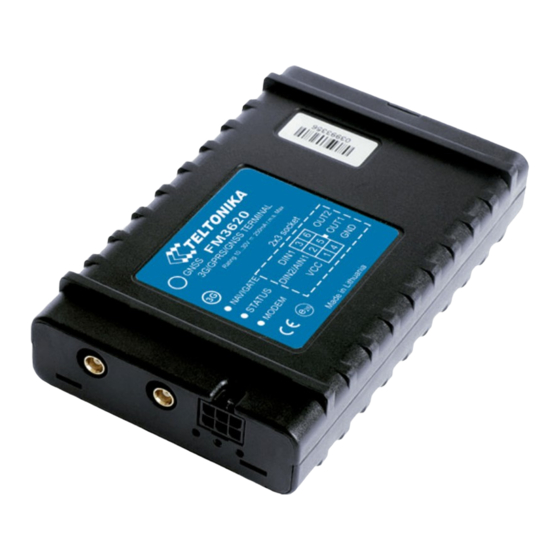
4-794628-0 or similar Storage relative humidity 5 ... 95 % (no Mini USB socket condensation) Table 1. FM3620 specifications When in Sleep mode, FM unit turns OFF GNSS module. When in Deep Sleep mode no data storing and sending is activated. - Page 10 Figure 1. FM3620 view & dimensions (tolerance ±2mm)
-
Page 11: Electrical Characteristics
Electrical characteristics VALUE Min. Typ. Max. Unit CHARACTERISTIC DESCRIPTION Supply Voltage: Supply Voltage (Recommended Operating Conditions) Digital Output (Open Drain grade): Drain current (Digital Output OFF) Drain current (Digital Output ON, Recommended Operating Conditions) Static Drain-Source resistance (Digital mOhm Output ON) Power supply current Deep sleep average on 12V 1,33... -
Page 12: Absolute Maximum Ratings
Drain-Source clamp threshold voltage (Absolute Maximum Ratings), = 2mA drain Digital Input Voltage (Absolute Maximum Ratings) Analog Input Voltage (Absolute Maximum Ratings) 3 CONNECTION, PINOUT, ACCESSORIES How to insert SIM card and attach battery into FM3620 device: Gently open FM3620 case using screwdriver... - Page 13 Remove FM3620 case Insert SIM card as shown Attach battery With screwdriver attach cover Attach top housing cover Device is ready...
-
Page 14: Installing Fm3620 Drivers
• MS .NET Framework V3.5 or later (http://www.microsoft.com http://avl1.teltonika.lt/downloads/tavl/Framework/dotnetfx35setupSP1.zip). Drivers: Please download Virtual COM Port drivers from Teltonika website: http://avl1.teltonika.lt/downloads/FM33/vcpdriver_v1.3.1_setup.zip Installing drivers: Extract and run VCPDriver_V1.3.1_Setup.exe. This driver is used to detect FM3620 device connected computer. Click ‘Next’ in driver installation window (figures below): Figure 2. -
Page 15: Navigate Led
Figure 4. Driver installation window You have now installed drivers for FM3620 device successfully. Navigate LED Behavior Meaning Permanently switched on GNSS signal is not received Blinking every second Normal mode, GNSS is working GNSS is turned off because: ... -
Page 16: Fm3620_C1 Socket 23
1W_Data 1W_PWR DIN 1 / AIN OUT 1 VCC (1030)V DC (+) GND(VCC(1030)V DC)(-) Figure 5. 26 socket pinout Pin Name Description Power supply for module. Power supply range VCC (10÷30) V DC (+) ÷ 30)V DC Energy consumption: GPRS: 200 mA r.m.s Max. -
Page 17: Usb
*** The described PINOUT is used only for FM3620_C1 hardware configuration!!! Mini USB connector Figure 6. Mini USB type B connector FM3620 connected to PC creates an STM Virtual COM Port, which can be used as a system port (to flash firmware and configure the device): Figure 7. COM-Ports Accessories 1 –... - Page 18 Output from external (FM3620 – pin4) digital sensor Digital Input Figure 8. Digital thermometer DS1820 and TTJ100 connection scheme Figure 9. I-Button DS1990A connection scheme Note: Teltonika does not provide any additional equipment like panic buttons, door sensors or others.
- Page 19 Digital input 2, FM3620_C1 or FM3620_C2 must be configured to use only one of them. Figure 10 shows the connection scheme to the FM3620 and fuel tank sensor through Analog input 1. After the connection to the tank fuel level sensor, calibration is needed. Calibration is needed because most fuel tank sensors are not linear.
- Page 20 In cases when sensor output signal is negative, an additional relay has to be installed to convert negative signal to positive. Figure 12. Inverting relay connection Immobilizer relay When connected as shown below, FM3620 disables engine starter when output is OFF. More details about relays can be found below. Figure 13. Immobilizer relay connection Relays An ordinary automotive relay is used to invert input signal or to immobilize engine starter.
-
Page 21: Firmware
Firmware must to be copied to “Firmware updater” folder. Only one firmware must be in folder. Connect FM3620 to PC with the USB cable. Launch “Firmware Updater”, select COM port to which device is connected, click connect, and when IMEI and Firmware version fields are filled, start the update. -
Page 22: Operational Basics
Figure 15. FM3620 firmware updating finished When you see a table like in Figure 15, it means that the firmware is sent to FM3620 successfully. Wait until system led stops blinking fast and you may now close the update window and start using your FM3620 device. -
Page 23: Deep Sleep Mode
When FM3620 detects movement, it starts counting distance using GNSS signal: every second it checks current location and calculates distance between current and previous point. It keeps adding these intervals until it is time to make a record, then FM3620 records its location... -
Page 24: Features
Vehicle speed is equal or higher than 30km/h Note: Green Driving Scenario is a factor on various cars and various drivers testing phase and can be subject to changes. Teltonika is constantly working on improvement of the functionality of the devices, and strongly recommends using the latest version of the firmware. -
Page 25: Trip
FM3620 has one user editable profile, which can be loaded from device, and saved. User can also revert to default settings, by pressing Load Defaults button. After any modification of configuration settings it has to be saved to FM3620 device, otherwise it will not be written to device. - Page 26 In Advanced Configuration mode FM3620 is more configurable. Figure 18. Configurator window FM3620 Configurator is divided into main areas: 1 – main button area, 2 – information area, 3 –settings menu, 4 – parameters and values menu, 5 – recommended configuration values.
-
Page 27: Read Records
‘Add Keyword’ / ‘Change Keyword’ / ‘Switch Security Off’– buttons are used to protect configurator from unauthorized access to configuration. Keyword is 4 – 10 symbol length. If keyword is set, every time user reconnects FM3620 to USB port, user will be asked to provide valid keyword when connecting FM3620 to configurator. - Page 28 FM3620 version can be still used as a standard FM3620. It can be configured to acquire and send data to server. It will be possible to store up to 3854 data records if GSM is not available at the moment. It will send data later when GPRS is available again.
-
Page 29: System Settings
(lower range gives higher accuracy of measurements), and input voltage; Object Motion Detection Settings, where user can configure 3 ways how FM3620 will detect stopped movement, and change its working mode (for working modes, read section 5.13) ... -
Page 30: Records Settings
Figure 21. System settings configuration Records settings Here user can modify if FM3620 device will send newest records first, meaning, that the most important thing is to know recent position of car, older records are being sent right after newest records arrive to AVL application. -
Page 31: Gsm Settings, Gprs Part
Essential fields in ‘SMS’ part are ‘Login’ and ‘Password’. The login and password are used with every SMS sent to FM3620. If login and password are not set, in every SMS sent to FM3620 device two spaces before command have to be used (<space><space><command>). -
Page 32: Gsm Settings, Operator List
5.12 GSM settings, Operator list Operators list – FM3620 can work in different modes (use different settings) according to the operator list defined. Operator list is used for Data Acquisition Mode switching (see chapter 5.13 Data Acquisition Mode settings for more details). -
Page 33: Data Acquisition Mode Settings
Figure 25. Operator list configuration If operator list is left empty, it will allow using GPRS to any GSM operator. Please note that FM3620 will work in Unknown mode only (make sure it is configured to allow data sending – GPRS context is enabled). - Page 34 If there are no operator codes entered into operator list, FM3620 will work in Unknown network mode ONLY. Figure 26. Data Acquisition Mode configuration Operator search is performed every 15 minutes. Depending on current GSM operator, Home, Roaming or Unknown mode can be changed faster than every 15 minutes. This process is...
- Page 35 New GPRS context is opened if time is 10 minutes till time checked in table. Therefore if all boxes are checked, FM3620 is able to open new connection anytime. At scheduled time match FM3620 checks for GPRS session activity.
- Page 36 Distance based acquire interval. If so, saves the record to memory. If not and speed is higher than 10km/h, then FM3620 checks if angle difference between last record and current record is equal or higher than Angle based acquire value.
-
Page 37: Features Settings
Min. time period Distance based data acquiring (Min. distance) – records are being acquired when the distance between previous coordinate and current position is greater than defined parameter value. Entering zero disables data acquisition depending on distance. Min. distance Angle based data acquiring (Min. angle) – records are being acquired when angle difference between last recorded coordinate and current position is greater than defined value. - Page 38 Figure 28. Scenarios configuration Digital Output (open drain grade) usage in scenarios: Green Driving DOUT1 is ON (if selected DOUT1) for: 3sec. if detected value is over (0; 30] % from preconfigured allowed value 5sec. if detected value is over (30; 50] % from preconfigured allowed value ...
-
Page 39: Trip Settings
5.14.2 Trip settings Trip window offers user to configure Trip feature. If Trip is enabled configuration of parameters are enabled. Start Speed – GNSS speed has to be greater than the specified Start Speed in order to detect Trip Start. Ignition Off Timeout –... -
Page 40: Geofencing Settings
5.14.3 Geofencing settings FM3620 has 5 configurable Geofence zones and it can generate an event when defined Geofence zone border is crossed. Frame border – frame border is an additional border around Geofence zone. It is additional area around defined zone used to prevent false event recording when object stops on the border of the area and because of GNSS errors some records are made inside area and some –... - Page 41 Figure 32. Geofence configuration AutoGeofencing settings AutoGeofence – the last known position after movement = off. If your car’s being taken away – you can be notified. The shape and size of the geofence zones are parameters. When object will leave geofence zone device will trigger an asynchronous message.
-
Page 42: Sms Events
AutoGeofence I/O event When any of the above events is triggered, FM3620 sends a configured SMS message to a defined phone number. If SMS events is activated, but there are no numbers defined in SMS events PreDefined Numbers list (figure 34), then the device will not send any messages. - Page 43 The sent SMS messages format is according to: “Date Time EventText” For example, if FM3620 is configured to send an SMS (figure 35), when Digital Input 1 reaches High level, with priority High and configured to generate event on both range enter and exit (figure36), then the sent SMS is: “2012/6/7 12:00:00 Digital Input 1”...
- Page 44 (numbers, letters and symbols in ASCII, except for comma “,”). ATTENTION! If FM3620 is in Deep Sleep mode and SMS event occurs with LOW priority (which does not wake up FM3620), then the device does not send the message. It is saved in device memory until it wakes up from Deep Sleep mode and GSM modem starts working normally.
- Page 45 Figure 38 Scenarios SMS event configuration When any of the scenarios events occurs, a text message will be sent to the predefined number. Trip In order to configure Trip SMS events click on Trip window and Enable Trip feature (figure 39). Then go to GSM ->...
- Page 46 Figure 40 Trip Start/Stop SMS event configuration Geofence Geofence SMS event is triggered and message sent when the device exits and/or enters a configured Geofence zone. The Geofence zone must be configured to generate an event On Exit, On Enter or On Both (figure 41). If No Event is selected, then it is not possible to turn on SMS events.
- Page 47 Figure 44 AutoGeofence SMS event configuration I/O events FM3620 sends SMS event message when a configured I/O property enters and/or exits its configured High/Low boundaries or Hysteresis event generation is chosen (Monitoring does not generate event, so SMS event could not be configured). Every IO element SMS event can be...
-
Page 48: I/Osettings
Figure 45 I/O event configuration Figure 46 I/O SMS event configuration 5.15 I/O settings When no I/O element is enabled, AVL packet comes with GNSS information only. After enabling I/O element(s) AVL packet along with GNSS information contains current value(s) of enabled I/O element. - Page 49 Speed (Km/h) Value in km/h, 0 – xxx km/h iButton ID iButton ID number Mode 0 – home on stop, 1 – home on move, 2 – roaming on stop, 3 – roaming on move, 4 – unknown on stop, 5 –...
- Page 50 Figure 47. I/O settings Enabled or disabled field – allows enabling I/O element so it is added to the data packet and is sent to the server. By default all I/O element are disabled and FM3620 records only GNSS coordinates.
-
Page 51: Monitoring
Note: I/O element’s “Movement sensor” Averaging constant is interpreted as Start Move Timeout in seconds (from 1 to 59). Start Move Timeout – is a time interval required for movement sensor to be in the moving state, to consider vehicle as moving. 5.15.1 Monitoring I/O monitoring starts after enabling I/O element and setting up I/O parameters as it is... -
Page 52: Sms Command List
Figure 51. Event generation according hysteresis algorithm 6 SMS COMMAND LIST Read chapter 5.11 to know how to construct a proper SMS message and send it to FM3620 device. All commands are case sensitive. While FM3620 operates in Deep Sleep mode and user tries to send SMS message it cannot arrive to FM3620 device, because GSM/GPRS module is disabled most of the time (wake up depends on Send Period parameter). -
Page 53: Getstatus
# - ID value. setparam # # Set parameter value according entered ID and Value. 1.# - ID value. 2.# - New Parameter Value getparam 1271 X X values can be 1,2,3. flush #,#,#,#,#,#,# Initiates all data sending to specified target server 1.# - IMEI 2.# - APN 3.# - LOGIN... -
Page 54: Getops
Day Of Week – indicates current day of week starting from 1 – Monday, 2 – Tuesday, etc. Time Indicates current GMT time WeekTime Indicates time in minutes starting from Monday 00:00 GMT Example: Clock Sync: 1 DOW: 4 Time 12:58 Weektime: 6538 6.1.3 getops Response details... -
Page 55: Getver
6.1.7 getver Response details Description Code Ver Firmware version Device IMEI IMEI Device ID Device ID is used to detect by server which type of configuration to load Bootloader Ver Bootloader Version Modem App Ver Version of modem application (veiks: nuo 00.05.14) Revision Firmware revision Example: Code Ver:01.06.15 Rev:1 Device IMEI:353976010139156 Device ID:000001... -
Page 56: Readio
Digital Output state Example: DI1:0 DI2:0 DI3:0 AIN:0.0611 DO1:0 DO2:0 6.1.10 readio # Response details Description I/O element ID Value I/O Element value Example: I/O ID:3 Value:0 6.1.11 setdigout ## Y1 Y2 Sets digital outputs to ON or OFF state (for some time if needed). Value is written as a row for OUT1 and OUT2 values. -
Page 57: Flush
6.1.16 flush #,#,#,#,#,#,# Initiates all data sending by GPRS to specified target server. Comma separated parameters go as numbered: 1.# - IMEI 2.# - APN 3.# - GPRS LOGIN 4.# - GPRS PASSWORD 5.# - IP 6.# - PORT 7.# - MODE (0-TCP/1-UDP) Parameters are separated by comma (no spaces needed). -
Page 58: Lvcangetinfo
KernVar: 49 MdlID: 8884443332221110” 7 Debug mode FM3620 is able to transmit its current state when connected to PC using USB cable. It is used to detect errors and provide information to possible solutions when operating as unexpected. Download Terminal from: http://avl1.teltonika.lt/Downloads/Software/Terminal.zip. -
Page 59: Parameter List
(value 1) module reduces level of power usage by turning GNSS module to sleep, in deep sleep mode (value 2) module turns GNSS module to sleep and switch GSM module off (note, that FM3620 do not receive SMS while in deep sleep). -
Page 60: Static Navigation (Id=1003)
8.2.5 Static Navigation (ID=1003) When static navigation is enabled, FM3620 filters out GPS jumps, when it is not moving. When it is disabled, it does not make any changes to collected GPS data. Minimum Maximum Recommended Goes with (depends on) -
Page 61: Records Parameters
Records parameters 8.3.1 Sorting (ID=1010) Record sorting parameter is responsible for record sorting order. Value of 0 arranging data starting from newest, while value of 1 arranging data starting from oldest. Minimum Maximum Recommended Goes with (depends on) Value value value value parameters... -
Page 62: Apn Name (Id=1242)
APN username (ID=1243) APN Password (ID=1244) 8.4.2 APN Name (ID=1242) Parameter defines GPRS Access Point Name. Minimum Maximum Recommended Goes with (depends on) Value value value value parameters type GPRS content activation (ID=1240) 32 char Empty S8[32] APN username (ID=1243) string APN Password (ID=1244) 8.4.3... -
Page 63: Protocol (Id=1247)
8.4.7 Protocol (ID=1247) Parameter defines GPRS data transport protocol. Module can use TCP or UDP transport protocol to send data to server. For TCP protocol value is 0, for UDP protocol value is 1. Minimum Maximum Recommended Goes with (depends on) Value value value... -
Page 64: Sms Data Sending Settings (Id=1250)
8.4.12 SMS data sending settings (ID=1250) Parameter allows or does not allow sending AVL data using binary SMS. If SMS use is not allowed value is 0 and 1 if SMS use is allowed. Minimum Maximum Recommended Goes with (depends on) Value value value... -
Page 65: Data Acquisition Modes Parameters
Here 16 , 17 and 18 operator codes are set. Note! Other operator codes are left unchanged in the configuration. Minimum Maximum Recommended Goes with (depends on) Value value value value parameters type Empty 7 digits Data Acquisition Modes parameters 8.5.1 Home Network GSM operator code “Vehicle on STOP”... -
Page 66: Home Network Gsm Operator Code "Vehicle Moving" Parameters
00011111 00000000 00000000 00000000 000000000 00000000 00000000 00000001 00000000 00000000 00000000 00000000 00000000 000000001 00000000 00000000 00000000 00000000 00000000 Red bits indicate that GPRS will be allowed every day except Saturdays and Sundays. Blue bits indicate 480 and 720 minutes (480min = 8h and 720min = 16h). So the parameter value should be: 1F,00,00,00,00,00,00,01,00,00,00,00,00,01,00,00,00,00,00 It should be sent as UTF8 encoded string. -
Page 67: Roaming Network Gsm Operator Code "Vehicle On Stop" Parameters
Min Angle (ID=1552) Min Speed Source (ID=1557) GPRS Week Time (ID=1555) 8.5.2.5 Min Speed Source (ID=1557) This parameter defines Source for speed difference calculation: 0 – GPS, 1 – LVCAN Minimum Maximum Recommended Goes with (depends on) Value value value value parameters type... -
Page 68: Roaming Network Gsm Operator Code "Vehicle Moving" Parameters
8.5.3.3 Send Period (ID=1564) This parameter indicates frequency (time interval in seconds) of sending data to server. Minimum Maximum Recommended Goes with (depends on) Value value value value parameters type Min Saved Records (ID=1563) 2592000 GPRS Week Time (ID=1565) 8.5.3.4 GPRS Week Time (ID=1565) Read chapter 8.5.1.4. -
Page 69: Unknown Network Gsm Operator Code "Vehicle On Stop" Parameters
8.5.4.4 Min Speed (ID=1576) This parameter indicaes speed difference in order to acquire new record. If speed difference between last recorded coordinate and current position is greater than defined value, new record is stored. If value is 0 it means no records by min distance will be saved. Minimum Maximum Recommended... -
Page 70: Unknown Network Gsm Operator Code "Vehicle Moving" Parameters
Minimum Maximum Recommended Goes with (depends on) Value value value value parameters type 2592000 8.5.5.2 Min Saved Records (ID=1583) This parameter defines minimum number of records in one data packet that can be sent to server. It has higher priority than Data Send Period (ID=1584). Minimum Maximum Recommended... - Page 71 8.5.6.3 Min Angle (ID=1592) This parameter indicates angle in degrees in order to acquire new record. If angle difference between last recorded coordinate and current position is greater than defined value, new record is stored. This parameter is operational, when speed is higher than 10km/h. If value is 0 it means no records by min angle will be saved.
-
Page 72: Features Parameters
8.5.6.7 Send Period (ID=1594) This parameter indicates frequency (time interval in seconds) of sending data to server. In order to send data to server GPRS parameters must be enabled Minimum Maximum Recommended Goes with (depends on) Value value value value parameters type Min Saved Records (ID=1593) -
Page 73: Max Allowed Speed (Id=1605)
8.6.5 Max allowed Speed (ID=1605) It is max allowed speed which can be reached. If this value exceeded Over speeding event will occur. Minimum Maximum Recommended Goes with (depends on) Value value value value parameters type Green Driving scenario (ID=1600) 8.6.6 OverSpeeding scenario (ID=1601) OverSpeeding scenario can be enabled to work with 3 different ways: Dout not control... -
Page 74: Trip (Id=1280)
8.6.10 Trip (ID=1280) This parameter enables ability to detect START and STOP of the trip. Minimum Maximum Recommended Goes with (depends on) Value value value value parameters type 8.6.11 Start Speed (ID=1281) This parameter represents speed, which is detected as minimum speed to indicate TRIP START and generate event. -
Page 75: Ignition Off Timeout (Id=1282)
with 3 different ways: Dout not control scenario (value Dout1 controls scenario (value 2), Dout2 controls scenario (value 3). To disable Immobilizer detection scenario value 0 is used. Minimum Maximum Default value Goes with ( value value param 8.6.14 iButton list checking scenario (ID=1608) iButton list... - Page 76 8.6.16 Jamming detection scenario (ID=1606) Jamming detection scenario can be enabled to work with 3 different ways: Dout not control scenario (value Dout1 controls scenario (value 2), Dout2 controls scenario (value 3). To disable Jamming detection scenario value 0 is used.
-
Page 77: Trip Continuous Distance Counting (Id=1283)
8.6.19 Trip Continuous distance counting (ID=1283) For this feature I/O#11 ODOMETER must be enabled. If I/O ODOMETER is enabled, and Continuous distance counting variable is set to Continuous (value 1), TRIP distance is going to be counted continuously (from TRIP start to TRIP stop) and shown as I/O ODOMETER value. Minimum Maximum Recommended... -
Page 78: Geofencing
detection scenario value 0 is used. Minimum Maximum Default value Goes with ( value value param 8.6.22 iButton list checking scenario (ID=1608) iButton list checking detection scenario enabled (value 1) or disabled (value 2). Minimum Maximum Default value Goes with ( value value param... - Page 79 All Geofencing parameters 8.6.23.4 Geofence Zone #1 Generate Event (ID=1032) Generate event on: a) On exiting zone – value 0; b) On entering zone – value 1; c) On both – value 2; Minimum Maximum Recommended Goes with (depends on) Value value value...
-
Page 80: Autogeofencing
For rectangle: Minimum Maximum Recommended Goes with (depends on) Value value value value parameters type -180 All Geofencing parameters Float For circle: Minimum Maximum Recommend Goes with (depends on) Value value value ed value parameters type 1000000 1000 All Geofencing parameters Float 8.6.23.8 Geofence Zone #1 Latitude (Y2) (ID=1036) If shape is rectangular, then ID=1036 is right upper corner Y coordinate. -
Page 81: Ibutton List (Id=7000-7499)
Minimum Maximum Recommended Goes with (depends on) Value value value value parameters type AutoGeofence event generating (ID=1104) 8.6.24.4 AutoGeofence event generating (ID=1104) Generate event: 0 – on exiting zone; 1 – on entering zone; 2 – on both; Minimum Maximum Recommended Goes with (depends on) Value... -
Page 82: I/O#1 Low Level (Id=2002)
Minimum Maximum Recommended Goes with (depends on) Value value value value parameters type I/O#1 Priority (ID=2000) I/O#1 Low level (ID=2002) -2147483647 2147483647 I/O#1 event generation type (ID=2003) I/O#1 averaging length (ID=2004) 8.7.3 I/O#1 Low level (ID=2002) Parameter defines low value of triggered I/O property. This parameter is used to set thresholds for I/O properties to generate events. - Page 83 I/O element I/O Element Number parameters I/O#0 – Digital Input 1 2000 – 2004 I/O#1 – Digital Input 2 2010 – 2014 I/O#2 – Analog Input 1 2020 – 2024 I/O#3 – Digital Output 1 2030 – 2034 I/O#4 – Digital Output 2 2040 –...
-
Page 84: Sms Event Configuration
SMS event configuration 8.8.1 I/O#1 element SMS event configuration (ID=5100) Command sets SMS warning on I/O#1 element. SMS Format: setparam X Y,W,Z X – ID Y – Enable/Disable (1/0) W – Telephone number INDEX (See 8.4.18 SMS Event Predefined Numbers paragraph, ID 150 –... - Page 85 LVC Fuel Consumed 5131 LVC Fuel Level (liters) 5132 LVC Engine RPM 5133 LVC Total Mileage 5134 LVC Fuel Level (percent) 5135 LVC Program Number 5136 LVC ModuleID 5137 LVC Engine Work Time 5138 LVC Engine Work Time (counted) 5139 LVC Total Mileage (counted) 5140 LVC Fuel Consumed (counted)
-
Page 86: Fm3620 With Light Vehicles Can Adapter Lv-Can200
9 FM3620 with Light Vehicles Can adapter LV-CAN200 Purpose of Light Vehicles Can Adapter LV-CAN200 LV-CAN200 is used to listening data from light vehicles. With this adapter FM3620 device is able to collect and send vehicle data. Figure 53 connection block diagram FM3620 shares the same USB port for connecting adapter and configuring device with PC. -
Page 87: Lv-Can200 Program Number Selection
LV-CAN200 must be set to program number which depends on vehicle model. Needed program number is always written on LV-CAN200 mounting scheme. Please contact Your Teltonika sales manager to get latest supported vehicle list and mounting scheme for your vehicle, please provide CAR manufacturer, model and year information. -
Page 88: Connecting Fm3620 With Light Vehicles Can Adapter
Figure 54 Adapter signaling led Connecting FM3620 with Light Vehicles Can adapter Connect USB Plug to FM3620 device, connect Light Vehicles Can adapter to other end of the cable. Connect Light Vehicles Can adapter Pin 1 and Pin 2 to cars CAN bus. CAN interface location of the supported light vehicle is described on mounting scheme. -
Page 89: Fm11 Configuration
FM3620 can be configured using “SCAN” function or “Offline Configuration” (Figure 58) SCAN function – is in use when FM3620 is connected to CAN adapter (Figure 56), then wait 10s (Note, that car engine must be started), disconnect adapter from FM3620, and connect PC USB cable to FM3620 Device (Figure 57). - Page 90 For example Speed changes, low fuel level, engine temperate, etc. Send data to server field – allows enabling CAN element so it is added to the AVL data packet and sent to the server. By default, all CAN elements are disabled and FM3620 records only GPS data.
-
Page 91: Parameters Id
Figure 58 Configurator example Available CAN Bus IO parameters and configuration can be found in Configurators CAN tab (Figure 58) and in next chapter “Parameters ID”. Parameters ID When no I/O element is enabled, AVL packet comes with GPS information only. After enabling I/O element(s) AVL packet along with GPS information contains current value(s) of enabled I/O element. -
Page 92: Sms Configuration
SMS Configuration All LV-CAN200 IO elements can be configured remotely via SMS command. ID number refers to specific LV-CAN200 IO element (table 9.2). The last ID number refers to sections – Property; Generation Type; Low and High levels (Table 9.3). Here’s example: ID 2013 –... -
Page 93: Can Program Number Request By Sms
Fuel level (proc.) Program number CAN Program Number request by SMS CAN program number can be obtained via SMS: SMS Text: “ lvcangetprog ” Response: “CAN Program Nr: XXX” Get LV-CAN info by SMS Full LV-CAN information via SMS: SMS Text: “ lvcangetinfo” Response: “Prog: 139 SWRevison: 6... -
Page 94: Connecting Wires
GND vehicle computer. Connecting the GND at an arbitrary point to the mass of the car is unacceptable, as static and dynamic potentials on the line GND will be unpredictable, which can lead to unstable FM3620 and even its failure. -
Page 95: Connecting Antennas
When placing antennas avoid easily reached places. Avoid GNSS antenna placement under metal surfaces. Avoid placing FM3620 device near car radio, speakers or alarm systems. GNSS antenna must be placed so its state is as horizontal as possible (if antenna is leant more than 30 degrees, it is considered incorrect mounting). -
Page 96: Change Log
10 CHANGE LOG Date Version Comments 2016-01-27 Preliminary draft release. 2016-01-29 Fixed Autogeofence Priority, Geofence Priority, Event Generation parameters. Fixed LVCAN Param ID. Fixed IO Priority values. 2016-02-02 Minor correction. 2016-02-09 DIN1 number correction in C2 hardware modification pinouts description 2016-02-09 DIN1 and DIN2 placement correction in C1 hardware modification pinouts description...
Need help?
Do you have a question about the FM3620 and is the answer not in the manual?
Questions and answers