
Related Manuals for DHS Fitness 7150


Summary of Contents for DHS Fitness 7150
- Page 1 MANUAL DE UTILIZARE DHS 7150 IMPORTANT! VA RUGAM SA CITITI CU ATENTIE ACEST MANUAL INAINTE DE A FOLOSI APARATUL. PASTRATI ACEST MANUAL PENTRU REFERINTA VIITOARE.
-
Page 2: Instructiuni De Siguranta
Instructiuni de siguranta Va multumim ca ati ales acest produs. Pentru a va garanta siguranta si sanatatea dumneavoastra, va rugam sa folositi corect aparatul. Va rugam sa cititi cu atentie acest manual inainte de a folosi aparatul. 1. Este important sa cititi intregul manual inainte de a incepe asamblarea si de a folosi aparatul. - Page 3 LISTA PARTILOR COMPONENTE:...
- Page 4 LISTA PARTILOR COMPONENTE: Description Description Protectie burete Φ23*3*210 Bolt ST3*10*Φ5.6 Dop Φ25*16 Senzor Roata dintata intermediara pe Maner sina de alunecare Bolt M6*40*S5 Piulita M8*H7.5*S13 Rotita delimitatoare Φ Saiba d6*Ф16*1.5*R16 31.5*34*Φ12.5 Saiba d8*Φ16*1.5 Bucsa Ф12*Ф8*38 Bolt M8*20*S5 Protectie Φ23*Φ12*37 Computer Bolt M10*24*S6 Suport computer 333*264*23.5 Saiba arc d10...
- Page 5 Tija support inferioara Bolt M5*10*Φ10 Bolt M6*48*20*S10 Saiba d5*Φ10*1 Roata dimtata intermediara Φ Bara stabilizatoare spate 23*32*Φ6 Saiba d6*Φ12*1.2 Protectie Φ32*24*Φ9*R25 Protectie sprijin bata Piulita M6*H6*S10 stabilizatoare spate Φ24*19 Capac piulita S17 Bolt M10*35*15*H6 Piulita M10*H9.5*S17 Saiba arc d8 Saiba d10*Φ25*2*R30 Saiba d5*Φ10*1 Bara stabilizatoara fata Bolt M8*75*13*S5...
-
Page 6: Instructiuni De Asamblare
INSTRUCTIUNI DE ASAMBLARE PASUL 1: #24 M10*H9.5*S17 2pcs #23 S17 2pcs Fixati bara stabilizatoare spate pe sina de alunecare (29) folosind boltul (52), saiba (25) si piulita (24), apoi atasati capacul piulitei (23) - Page 7 PASUL 2: #24 M10*H9.5*S17 2pcs #23 S17 2pcs Fixati bara stabilizatoare fata (26) pe tija suport fata (15) folosind boltul (52), saiba (25) si piulita (24), apoi atasati capacul piulitei (23).
- Page 8 PASUL 3: #7 M8*20*S5 2pcs #17 M8*16*S5 2pcs #6 d8*Φ16*1.5 2pcs #16 d8*Φ20*2*R16 2pcs #53 d8 2pcs Φ14*88 1. Fixati sina de alunecare (29) pe tija support fata (15) folosind boltul (7), saiba arc (53)si saiba (6). 2. Fixati tija suport inferioara (18) pe sina de alunecare (29) folosind boltul (17) si saiba (16).
- Page 9 PASUL 4: #7 M8*20*S5 4pcs #6 d8*Φ16*1.5 4pcs #53 d8 4pcs Φ14*88 1. Fixati manerul (3) pe tija suport fata (15) folosind boltul (7), saiba arc (53) si saiba (6). 2. Conectati firul trunchiului 2 (58a) folosind firul computerului (8a) si atasati mansonul de plastic (59).
- Page 10 USER’S MANUAL Important! Please read this manual carefully before use this equipment.
-
Page 11: Important Safety Notice
IMPORTANT SAFETY NOTICE Thank you for purchasing our product. Proper use can ensure your safety and health, so please read the following text carefully before using this equipment. 1. It is very important to read all the instructions carefully before assembling or operating this product. -
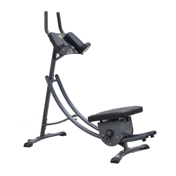
Page 12: Exploded View
Exploded view... -
Page 13: Parts List
Parts list Description Description Foam grip Φ23*3*210 Bolt ST3*10*Φ5.6 End cap Φ25*16 Sensor Handlebar Idler wheel on slide rail Bolt M6*40*S5 Nut M8*H7.5*S13 Wheel for limitΦ Washer d6*Ф16*1.5*R16 31.5*34*Φ12.5 Washer d8*Φ16*1.5 Bushing Ф12*Ф8*38 Bolt M8*20*S5 Limit cushionΦ23*Φ12*37 Computer Bolt M10*24*S6 Board for computer Spring washer d10 333*264*23.5... - Page 14 Support pad for Rear Nut M6*H6*S10 stabilizer Φ24*19 Bolt M10*35*15*H6 Nut coverS17 Nut M10*H9.5*S17 Spring washer d8 Washer d10*Φ25*2*R30 Washer d5*Φ10*1 Front stabilizer Bolt M8*75*13*S5 End cap ZT62*27*1.4 Bolt M8*50*15*S5 57a/b Trunk line1 End capΦ37*29 58 a/b Trunk line2 Slide rail Plastic sleeveΦ14*88...
- Page 15 Assembly Step 1: #24 M10*H9.5*S17 2pcs #23 S17 2pcs Lock the rear stabilizer to slide rail (29) with bolt (52), washer (25) and nut (24) and then attach the nut cover (23)
- Page 16 Step 2: #24 M10*H9.5*S17 2pcs #23 S17 2pcs Lock the front stabilizer (26) to front support tube (15) with bolt (52), washer (25) and nut(24) and then attach the nut cover(23)
- Page 17 Step 3: #7 M8*20*S5 2pcs #17 M8*16*S5 2pcs #6 d8*Φ16*1.5 2pcs #16 d8*Φ20*2*R16 2pcs #53 d8 2pcs Φ14*88 1. Lock the slide rail (29) to front support tube (15) with bolt (7), washer (53) and washer(6). 2. Lock the lower support tube (18) to slide rail (29) with bolt (17), washer (16). 3.
- Page 18 Step 4: #7 M8*20*S5 4pcs #6 d8*Φ16*1.5 4pcs #53 d8 4pcs Φ14*88 1. Lock the handlebar (3) to front support tube (15) with bolt(7),washer(53) and washer(6). 2. Connect the trunk line2 (58a) with computer line (8a) and attach the plastic sleeve (59), assembly finished.
Need help?
Do you have a question about the 7150 and is the answer not in the manual?
Questions and answers