Table of Contents

Summary of Contents for Promax AC-726
- Page 1 Test Equipment Depot - 800.517.8431 - 99 Washington Street Melrose, MA 02176 - TestEquipmentDepot.com AC-726 CABLE AND ANTENNA ANALYSER USER'S MANUAL VERSION Version Date Software Version April 2016 152.100.100 - 0 MI2756 -...
- Page 2 Not taking any safety precautions or following the instructions will violate the safety standards of design, manufacturing and application of these instruments. In no case will PROMAX bear the responsibilities for consequences incurred by violation of the following instructions.
- Page 3 Symbols related with safety: Descriptive Examples of Over-Voltage Categories Cat I Low voltage installations isolated from the mains. Cat II Portable domestic installations. Cat III Fixed domestic installations. Cat IV Industrial installations.
-
Page 4: Table Of Contents
Set DTF parameter ..............36 4.2.1 Set Distance parameter ............. 37 4.2.2 Set Cable parameter ..............38 4.2.3 Set Window Function ..............39 OSL Calibratrion................39 Freq-Return Loss, Freq-VSWR, Cable-Loss measurement ....40 DTF-VSWR, DTF-Return Loss measurement ........41 AC-726 PERFORMANCE............... 42... -
Page 5: General Information
AC-726 product is portable, easy to learn and use. Has the characteristics of powerful function, fast operation, integrated intelligent etc. AC-726 product is equipped with a large and easy to read color LCD which can display the measurement data, trace and figure. This product has rich peripheral interface, users can easily backup or upload data. -
Page 6: The Appearance Introduction Of Equipment
2 EQUIPMENT DESCRIPTION The head cover Figure 1. The head cover contains a variety of interface. A detailed description of the following. RF connector: To connect cable and antenna unit to be tested. RJ45 LAN: Reserved. Ear socket: Reserved. USB Device port: To connect PC, then users can run special software to analyze and manage measurement data. -
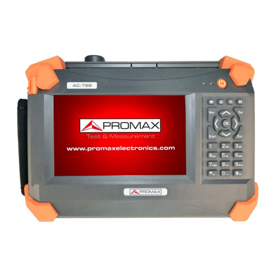
Page 7: Front Panel
Front panel Figure 2. Screen display area Indicator LED Power ON (short press) / OFF (long press) Keypad Pen holder Description for indicator lights: Position State Meaning Battery Charging… Left Green Battery Charge fully Power off Right Green Power on Measuring…... - Page 8 Description for hard keyboard: Adjust the display screen brightness, there are four levels. Switch display mode (black and white, normal, night vision, and high contrast). Preview, save the measurement picture. Save calibration and measurement curve. Popup or down the right menu. Quick start measurement.
-
Page 9: User Interface And Menu Instructions
3 USER INTERFACE AND MENU INSTRUCTIONS Turn on the instrument Press , equipment will display the boot picture. During startup, the right light turns red, the system will initialize DSP system, self check system state, etc. When main interface appear, the boot process end, the right light turns green. Main interface Figure 3.: April 2016... -
Page 10: Main Interface
Main interface Click “MEASUREMENT” Icon, 5 sub-icons appear, corresponding to the five measurement modes: DTF (distance fault) return loss, DTF-VSWR, Frequency return loss, Frequency-VSWR, cable loss. Click the icon, the system will go into the corresponding measurement interface. Main interface Figure 4.: NOTE: Click other icons in the main interface (CALIBRATION, SETTINGS, HELP),... -
Page 11: Measurement Interface
Measurement Interface Figure 5. Measurement interface mainly consists of the following parts: Name Position Function and Description Display system status Status bar measurement information. For details, see the later chapter. Function Right Note: If some menu are selected, this menu part may will refresh. - Page 12 Detailed description: Function Function and Description. Power management mode: standard and power saving mode. Measurement state: idle and measuring. Time: year/month/date/hour/minute. The adapter and battery state: 1. Connect an external adapter, without battery - display adapter icon; 2. Connect an external adapter, with battery charging - display charging icon;...
-
Page 13: The Function Menu Description
RL/SWR: fast switching between the return loss and VSWR measurement. Marker: For details see later chapter. Limit: For details see later chapter. Function Scale: For details see later chapter. menu 2 Smooth/Average: turn on/off Smooth/Average function. User can utilize these function to observe and analyze measurement dat. - Page 14 Marker setting menu Figure 7.: Marker setting menu Figure 8.: The user can define the position of marker line by the following ways: The soft keyboard to enter digital value. ► The hard keyboard to enter digital value. ► Touch screen directly with touch pen to move and define the location. ►...
-
Page 15: Limit Line
After the location of the mark line is determined, users need to confirm the operation (soft keyboard "Enter" key or hard keyboard "OK" key). Users also can click on the "mark to the peak" or "mark to the valley" to determine the location of the mark line. - Page 16 Limit setting menu Figure 10.: The user can define the limit line position by the following ways The soft keyboard to enter digital value ► The hard keyboard to enter digital value ► Touch screen directly with touch pen to move and define the location ►...
-
Page 17: Scale
3.4.3 Scale Scale function is mainly used to adjust the Y axis, convenient for users to view data. Scale menu Figure 11.: Manual scale setting menu Figure 12.: April 2016... -
Page 18: File
The upper and lower coordinate can only be edited if “manual” menu is activated. 3.4.4 File The user can save measurement data or picture to PC; also can recall measurement data from PC to AC-726. This function facilitate users to analyze the measurement data later. File menu Figure 13.: April 2016... - Page 19 Save file interface Figure 14.: Image preview interface Figure 15.: April 2016...
- Page 20 File import interface Figure 16.: File delete interface Figure 17.: April 2016...
-
Page 21: Display
Name Function and Description Save Data The default file type is .csv format. The default file name includes the measurement mode, frequency, measuring points, the time information. users can choose to save in the local memory or external memory Only support measurement and calibration data. Save The default file type is the.JPG format. - Page 22 Display setting menu Figure 19.: Name Function and Description Save current data to memory. Note: Only one data can save. Data->Mem The data can be the current measurement data, can also be a historical data. It can recall from local or external disk. Only Data Display the current measurement data.
-
Page 23: Average/Smooth
3.4.6 Average/Smooth Average/Smooth menu Figure 20.: Name Function and description. Smooth For a single curve do smooth operation. Average For 2 relative curve do average operation. April 2016... -
Page 24: Calibration Interface
The user can save current calibration data to the local or external disk, or Import history calibration data to AC-726. Before calibration, the user need to set the correct parameters, Mainly refer to the frequency and measurement points. The completion calibration, the corresponding curve will display on the screen. - Page 25 Is the electrical exact Return length of open electrical length of Phase/Impedenc-e Loss/VSWR/cable and short cal kit open and short cal measurement Loss measurement same? kit known? unknown support do not support know support support know support support The return loss of 50 ohms cal kit need to be > 42. The VSWR of open/short cal kit need to be >100.
-
Page 26: System Settings Interface
System Settings Interface In the system settings interface, users can do all kinds of system configuration. Language setting interface Figure 23.: Clock setting interface Figure 24.: April 2016... - Page 27 Back light setting interface Figure 25.: Display mode setting interface Figure 26.: April 2016...
- Page 28 Fan mode setting interface Figure 27.: Power mode setting interface Figure 28.: April 2016...
- Page 29 File manager interface Figure 29.: NOTE: 1. Please make sure that the external memory has been inserted before operating “File Management”; 2. User must return to the superior interface before removing the external disk to make sure files performed. Load default setting interface Figure 30.: April 2016...
- Page 30 Name Function and Description Language Support English / Spanish Clock Year, month, date, hour, minute and second. Back Light Support 4 levels brightness adjustment. 4 modes: Default: Display Mode Black-white: used for printing High-contrast: Night vision: used in night environment Three modes: Auto;...
-
Page 31: Help Interface
Help Interface Version information interface Figure 31.: Device information interface Figure 32.: April 2016... - Page 32 Disk information interface Figure 33.: Battery information interface Figure 34.: April 2016...
- Page 33 Firmware update interface Figure 35: On the help menu, the user can view a variety of instruments information; meanwhile users can upgrade the firmware. Name Function and Description Incluyes hardware version software version instrument Version Info serial number, etc. Includes: board temperature, battery...
-
Page 34: Common Operating Instructions
4 COMMON OPERATING INSTRUCTIONS Set frequency parameter The user needs to properly set the frequency parameter before testing. In the following ways users can enter the frequency setting interface. Calibration setting interface Figure 36: April 2016... - Page 35 DTF setting interface Figure 37: Frequency setting interface Figure 38: April 2016...
-
Page 36: Set Dtf Parameter
In the "calibration" interface, click on the "parameter" button ► In the "frequency return loss" or "frequency VSWR" or "cable loss ► "measurement interface, click on the "parameter" button The user can also input frequency parameters in "DTF parameter setting" ►... -
Page 37: Set Distance Parameter
DTF setting interface Figure 39 The user can complete the following functions at the DTF parameter setting interface. Enter frequency information and measure points. ► Enter the distance information. ► Enter the cable parameters. ► Select the window function. ► Set unit (support metric and Imperial). -
Page 38: Set Cable Parameter
For the convenience of users, the system will automatically display the relevant information (the maximum allowed cable length: Dmax; resolution Δ D) in the upper right corner. For example: N = 551; Vp = 0.85; F1 = 25 MHz, F2 = 4000 MHz. -
Page 39: Set Window Function
Figure40. 4.2.3 Set Window Function In the distance to the fault analysis, if the location of the two connectors are close, because of the influence of spectral leakage, two connectors will be influenced each other. If return loss of one connector is much smaller than another one, most probably it will be lost and can’t be recognized. -
Page 40: Freq-Return Loss, Freq-Vswr, Cable-Loss Measurement
Users can directly calibrate at the RF port, also can calibrate with a high performance cable connected to RF port. If the former, usually, the calibration curve of 50 ohm load will be significantly lower than the other two. If calibration is completed, the user can start measurement. The user can also select the file menu to save the calibration data in the local or external disk. -
Page 41: Dtf-Vswr, Dtf-Return Loss Measurement
DTF-VSWR, DTF-Return Loss measurement The measurement can be used to verify the power matching performance of different position of cable and antenna system, then user know a certain position joint connection quality. X axis coordinate is distance, Y axis coordinate is VSWR, or return loss. -
Page 42: Ac-726 Performance
5 AC-726 PERFORMANCE Specification Frequency Range 25-4000 MHz Frequency 100 kHz Resolution Frequency +/-25 ppm Accuracy Output signal level 0 dbm (typical) Measurement 3.5 ms / point speed Measurement point 137, 251, 551, 1103 Directivity 42 dB (after calibration) On-channel 17 dBm > 1 MHz away from carrier Interference freq. - Page 43 General Information RF Connector Type N, female Input impedance 50 Ohm Display 7 inch resistor touch LCD, 800*480 resolution 1 USB Host Data interface 1 USB Device 1 10M/100M adaptive LAN Storage >2000 curve Language Spanish, English Type: Li-Ion Battery 11.1 V 7800 mA 110~240 50~60 Hz AC input, 16 V 3.75 A DC External Adaptor...
- Page 44 PROMAX ELECTRONICA, S. L.
Need help?
Do you have a question about the AC-726 and is the answer not in the manual?
Questions and answers