Table of Contents
Advertisement
Advertisement
Table of Contents

Related Manuals for IBA ibaMS8xIEPE

Summary of Contents for IBA ibaMS8xIEPE
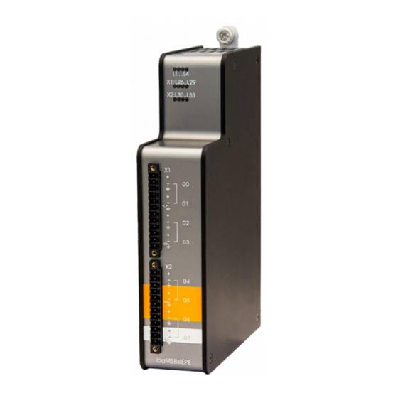
- Page 1 Input module for IEPE vibration sensors Manual Issue 1.3...
- Page 2 However, the information in this publication is updated regularly. Re- quired corrections are contained in the following regulations or can be downloaded on the Inter- net. The current version is available for download on our web site www.iba-ag.com. Windows ®...
-
Page 3: Table Of Contents
8.3.2 Update via ibaPDA ..................18 Module Information / Diagnostics ..............19 8.4.1 Diagnostics ....................19 8.4.2 Web Interface ....................19 iba Applications .................... 21 Configuration in ibaPDA................21 9.1.1 General settings ..................21 9.1.2 Configure inputs ..................23 9.1.3 Error and status signals ................ - Page 4 Manual ibaMS8xIEPE Technical Data ....................29 10.1 Main data ....................29 10.2 Analog inputs ....................29 10.3 Dimensions ....................31 Support and contact ..................32 Issue 1.3...
-
Page 5: About This Manual
Manual About this manual In this manual, you learn a lot about the design of the ibaMS8xIEPE device and how to use and operate it. You can find a general description of the iba-modular system and further information about the design of the central units and how to use and operate them in separate manuals. -
Page 6: Target Group
Manual ibaMS8xIEPE Target group This manual addresses in particular the qualified professionals who are familiar with han- dling electrical and electronic modules as well as communication and measurement tech- nology. A person is regarded to as professional if he/she is capable of assessing safety and recognizing possible consequences and risks on the basis of his/her specialist training, knowledge and experience and knowledge of the standard regulations. -
Page 7: Used Symbols
Manual Used symbols If safety instructions or other notes are used in this manual, they mean: The non-observance of this safety information may result in an imminent risk of death or severe injury: • By an electric shock! Due to the improper handling of software products which are coupled to input and •... -
Page 8: Introduction
The ibaMS8xIEPE module is member of the iba-modular system. The modular concept of the iba-modular system is designed on the basis of a backplane. You can plug on this backplane not only the CPU, but also up to 4 input/output modules. The power supply of the I/O modules is provided by the backplane bus. -
Page 9: Scope Of Delivery
ibaMS8xIEPE device 2 x 12-pin multi-pin connector Manual (German and English) DVD „iba Software & Manuals“ (only for single delivery) Safety instructions Proper use The device is an electrical apparatus. It is only allowed to use the device for the following applications: ... -
Page 10: System Requirements
Manual ibaMS8xIEPE System Requirements Hardware Central unit: ibaPADU-S-IT-2x16 or ibaPADU-S-CM (version 02.12.004 or later) Backplane unit, e. g. ibaPADU-B4S Software ibaPDA version 6.35.0 or later ibaLogic-V5 version 5.0.3 or later Issue 1.3... -
Page 11: Mounting, Connecting, Dismounting
Manual Mounting, Connecting, Dismounting Works on the device must NOT be done when it is under voltage! Always disconnect the central unit from the power supply! Note Mount one or more modules on the right next to the central unit (slot X2 to X5 can be freely selected). -
Page 12: Device Description
Device is not working (switched off) L2: yellow Access to the backplane bus L3: white L4: red Normal status, no faults Flashing Device failure Important note When the LED L4 indicates a failure, please contact the iba Support. Issue 1.3... -
Page 13: Status Of Iepe Inputs
Manual 7.2.2 Status of IEPE inputs LED per Status IEPE mode AI mode channel L26 … L33 Channel not active ± (0 V … 0.3 V) Green ± (0 V … 4.5 V) ± (0.3 V… 21.6 V) 0…90%... -
Page 14: Filter
Manual ibaMS8xIEPE When set to IEPE mode (default setting) an integrated constant current source provides 4 mA (30 V DC) for the connection of IEPE sensors. However, when the inputs are used as 24 V input, the configuration to 24 V mode has to be done in ibaPDA before wiring, see chapter 9.1.2! -
Page 15: Connection Diagram / Pin Assignment
Manual 7.3.2 Connection diagram / pin assignment Here, you can connect 8 input signals (0 ... 7), each bipolar plus grounding. 2 input chan- nels are grouped to one root. Each connector /each root is galvanically isolated. Figure 3:... -
Page 16: Error And Status Signals
Manual ibaMS8xIEPE 7.3.3 Error and status signals The following table shows the error and status signals available in different operating modes: IEPE AI-24 V AC AI-24 V DC Status signal Data valid Error signal Broken line ... -
Page 17: Start-Up / Update
In this case, a new update file has to be installed for the “overall release version“. If you want to get the current update file, please contact the iba Support. You will also find it on the “iba Software & Manuals“ DVD included in delivery of the module (directory: 02_iba_Hardware\ibaPADU-S\01_Firmware). -
Page 18: Update Via Web Interface
Important note The Web interface is available only with the central unit ibaPADU-S-IT-2x16. Start the Website of the iba-modular system in your browser and select the central unit. On the “update“ tab, click on the <Browse…> button and choose the <padusit2x16_ v[xx.yy.zzz].iba>... -
Page 19: Module Information / Diagnostics
Important information about the iba-modular system, like hardware version, firmware ver- sion, FPGA version and serial number is displayed in the “Diagnostics” tab. Open the ibaPDA I/O Manager and choose your iba-modular system in the tree structure (see also the figure above). - Page 20 Manual ibaMS8xIEPE 8.4.2.2 „notes“ tab On the “notes“ tab, you can enter notes, e.g. for notes on wiring or on recording of changes. By clicking on <save notes>, the notes are permanently stored on the device. Figure 7: „notes“ tab...
-
Page 21: Iba Applications
The automatic detection requires a bidirectional FO connection from the ibaPDA com- puter to the central unit. Other documentation If you want to install the iba-modular system at first, refer to the manual of the central unit, chapter “Configuration with ibaPDA”. 9.1.1 General settings If the module is detected, click on the module in the signal tree and the “General”... - Page 22 Manual ibaMS8xIEPE Locked True: the module can only be changed by an authorized user. False: the module can be changed by any user. Enabled Data capturing for this module is enabled. Name You can enter a name for the module.
-
Page 23: Configure Inputs
Configure inputs The following settings apply to the “Analog” tab: Figure 10: I/O Manager ibaMS8xIEPE – Analog tab Name You can enter a name for the signal and two additional comments (click on the icon in the Name field). -
Page 24: Error And Status Signals
Manual ibaMS8xIEPE Min/Max When the modes 24V AC or 24V DC are selected, the columns „Min“ and „Max“ ap- pear additionally. Here, you may define an upper and a lower limit of the measuring range. The nominal voltage level of +/-24 V is assigned to a physical value. - Page 25 Manual Figure 11: I/O Manager ibaMS8xIEPE – Digital tab Name The signal names are already pre-defined, you can enter two additional comments (click on the icon in the Name field). Channel […] broken line (only in IEPE mode) Status signal indicates, whether there is a broken line or a channel is not con- nected.
-
Page 26: Configuration With Ibalogic-V5
“Tools – I/O Configurator“ menu. When you click on the <Update hard- ware> button, then ibaLogic detects the module. Figure 12: Inputs ibaMS8xIEPE The analog input channels and the status signals are displayed in the „Inputs“ tab. The inputs’ operating mode can be selected from a dropdown-menu, see chapter 7.3: ... - Page 27 Manual Mode selection for the channels 1, 3, 5 and 7: If “Buffered Access“ is enabled, you can see additional input and output signals: Figure 13: Additional signals when buffered access is enabled Note You need to apply the “Buffered Access“ by clicking on the <Apply> button. Only then, you will see additional signals in the signal tree that can be configured as output or input resources.
- Page 28 Manual ibaMS8xIEPE Signal Description Inputs AI_IEPE_Ch[00…07] Analog input signals AI_Ch[00…07]_NotConnected Status signal indicates, whether there is a broken line or a channel is not connected (only in IEPE mode) AI_Ch[00…07]_Shorted Status signal indicates a short circuit (only in IEPE mode) AI_Ch[00…07]_DataValid...
-
Page 29: Technical Data
Manual Technical Data 10.1 Main data Short description Name ibaMS8xIEPE Description Input module with 8 analog inputs and different modes: DC, AC and IEPE: 4 x IEPE non-adjustable, 4 x IEPE / DC / AC adjustable Order no. 10.124302... - Page 30 Manual ibaMS8xIEPE Filter RC filter AI-24 V DC R/C low-pass, 1st order, 25 kHz AI-24 V AC Like AI-24 V DC, in addition R/C high-pass, 1st order, 1 Hz IEPE R/C high-pass, 1st order, 1 Hz or 0.1 Hz, can be adjusted...
-
Page 31: Dimensions
Manual 10.3 Dimensions (Dimensions in mm) Figure 14: Module dimensions Issue 1.3... -
Page 32: Support And Contact
Mailing address iba AG Postbox 1828 D-90708 Fuerth Germany Delivery address iba AG Gebhardtstrasse 10 D-90762 Fuerth Germany Regional and Worldwide For contact data of your regional iba office or representative please refer to our web site www.iba-ag.com. Issue 1.3...