Daktronics Sportsound SSR-200 Operation Manual
Hide thumbs
Also See for Sportsound SSR-200:
- Quick start manual (5 pages) ,
- Quick start manual (5 pages) ,
- Installation instructions (2 pages)

Related Manuals for Daktronics Sportsound SSR-200


Summary of Contents for Daktronics Sportsound SSR-200
- Page 1 Sportsound Rack ® SSR-200 Operation Manual DD2298630 Rev 4 – 07 August 2015 201 Daktronics Drive PO Box 5128 Brookings, SD 57006-5128 Tel: 1-800-DAKTRONICS (1-800-325-8766) Fax: 605697-4746 www.daktronics.com/support...
- Page 2 – graphic, electronic, or mechanical, including photocopying, taping, or information storage, and retrieval systems – without written permission of the publisher. Sportsound is a registered trademark of Daktronics, Inc. All other trademarks are property of their respective companies. ®...
-
Page 3: Table Of Contents
Parts ..........................21 SSR-200 Components ............................21 Optional Components ............................21 Section 6: Daktronics Exchange and Repair & Return Programs ..............23 Exchange Program ............................. 23 Before Contacting Daktronics ........................23 Repair & Return Program ..........................24 Shipping Address............................24 Daktronics Warranty &... - Page 4 Appendix A: Reference Drawings .......................... 25 Appendix B: Supplementary Manuals ........................27 Appendix C: Daktronics Warranty and Limitation of Liability ................29 Table of Contents...
-
Page 5: Introduction
System Riser Diagram ....................Drawing D-1007804 All drawings referenced in this manual are found in Appendix A. Daktronics identifies manuals by the DD or ED number located on the cover page. For example, this manual would be referred to as DD2298630. -
Page 6: Daktronics Nomenclature
Replacement Parts List in Section 5 use the label to order a replacement. Section 6 02/19/12 Rev. 1 describes the Daktronics Exchange Policy and the Repair & Return Program. Refer to figure 2: Part Label these instructions if replacing or repairing any display component. -
Page 7: Ssr-200 Components
Section 2: SSR-200 Components Overview Reference Drawing: Schematic/Layout; Sportsound Rack 200 ..............Drawing B-1190065 Figure 3 displays the various announcer’s rack components that are visible after removing the protective covers. Refer to Drawing B-1190065 in Appendix A for rack component and connection locations as well as a detailed wiring schematic. -
Page 8: Standard Equipment
• IR, RS-232c (9-pin D-sub), and GPIO (25-pin D-sub) controllable Announcer’s Interface The Daktronics Announcer’s Interface (Figure 6) includes one (1) balanced MIC output, one (1) balanced AUX input, and headphone jacks; headphone volume control knob; and momentary or continuous microphone activation buttons. Microphone and headphones are provided. -
Page 9: Laptop Interface
Laptop Interface This portable, durable balanced audio converter allows connection of a laptop or mp3/music player into pro-level mixers (Figure 7). Other features include: • 1/8" (3.5 mm) male input • Balanced XLR male output • Adjustable output volume control •... -
Page 10: Optional Equipment
Optional Equipment ADA Hearing Assist System The Listen LT-800 Stationary Transmitter in the audio rack allows individuals to ® experience every word at an event. This system is designed to broadcast the audio signal throughout the facility. It is capable of transmitting to multiple receiver types and its adjustable receivers allow each user to have full volume control. -
Page 11: Self-Powered Monitor Speaker
Self-Powered Monitor Speaker The Yamaha MSP3 monitor speaker (Figure 13) features a compact bass reflex cabinet, with a 3.94" (100 mm) two-way cone speaker and a 0.87" (22 mm) dome speaker. Other features include: • Three inputs: one ¼" phone, one RCA, one XLR •... -
Page 13: Setup & Operation
Section 3: Setup & Operation Setup Before Beginning: Place the rack on a flat, sturdy surface. Remove the cover pieces by twisting the knobs away from each other, and set them aside. Accessories are located in a separate case. Refer to the steps below and Figure 17. - Page 14 Fiber Box (outdoor) Announcer’s Wall Plate Interface (indoor) (Gen II) Rear View Laptop Interface figure 17: Rack Setup w/ Announcer's Interface (Gen II) Setup & Operation...
-
Page 15: Mixer Operation
Mixer Operation Refer to Figure 18 for an overview of the mixer components and controls. figure 18: Mixer Layout Inputs Outputs Trim/Gain Knob Phantom Power PFL & Mute Buttons VU Meter Channel Sliders/Faders Master Sliders/Faders Setup & Operation... - Page 16 Basic instructions are described below. For more information about mixer operation, refer to the Soundcraft EFX EPM User Guide. • Ensure all source equipment is turned on and operational (refer to appropriate pages). • For each input channel (source) in use, verify the following adjustments (Figure 19): –...
-
Page 17: Wireless Mic System Operation
Wireless Mic System Operation Basic instructions are described below. For more information about wireless mic system operation, refer to the Shure QLX-D Wireless System User Guide. ® ® Note: For systems built prior to November 2014, refer to the Shure Wireless System User Guide ®... -
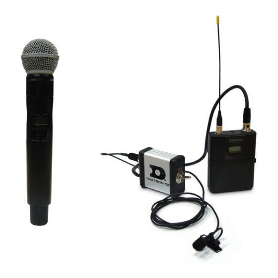
Page 18: Wireless Mic & Bodypack Operation
IR Window Power Wireless Mic & Bodypack Operation Power ON/OFF IR Window Power ON/OFF figure 24: Wireless Mic & Bodypack Controls Open the battery cover. Insert new or fully-charged AA batteries prior to each use, and always have spares on hand. Power on the transmitter device (Figure 24). -
Page 19: Microphone Best Practices
Microphone Best Practices • Keep handheld microphones 4-6 inches (102-152 mm) from the mouth (about the width of a hand). “P-pops” are loud sounds created by the release of breath when saying letters like “p” or “b”. To avoid P-pops, keep handheld microphones below the mouth, angled toward the nose at a 45° angle. Do not point the front of the microphone straight at the mouth. - Page 20 figure 25: Optional Personal Stereo Monitor System Setup & Operation...
-
Page 21: Hearing Assist System Operation (Optional)
Hearing Assist System Operation (Optional) Basic instructions are described below and shown in Figure 26. For more information, refer to the Listen ® 800 Stationary Transmitter, Listen LR-400 FM Receiver, and Listen LA-122 Universal Antenna Kit Users ® ® Manuals. Press POWER to turn on the transmitter if it is not already on. -
Page 23: Maintenance & Troubleshooting
This list does not include every possible problem, but it does represent some of the more common situations that may occur. If individual components fail to work, refer to troubleshooting sections in the manufacturers’ manuals. If the problem persists, please contact Daktronics for assistance. Symptom/Condition... - Page 24 Symptom/Condition Possible Cause Potential Solution For Wireless The battery is not installed properly in the Reinstall the battery properly transmitter The battery is not providing full power Charge or replace battery No signal present at mixer The transmitter is not switched to the ON from wireless microphones Switch the transmitter to the ON position position...
-
Page 25: Replacement Parts
Section 5: Replacement Parts SSR-200 Components Part Description Part Number Announcer’s Interface 0A-1534-0093 Announcer's Interface; Push-to-Talk A-3698 Desk Microphone Stand A-1954 Headphones, ¼" Phone A-1962 Dynamic Vocal Microphone A-2790 Wallpack Transformer, 12VAC; 6' Cord T-1118 2' XLR Cable W-1917 15’ Cable, Announcer Box to Mixer W-2074 Referee Headset Microphone A-1972... - Page 26 Part Description Part Number Single Muff Microphone Headset A-2382 USB Audio Interface A-2493 Shure PSM900 Personal Monitor System; Band L6 – 656-692 MHz A-2719 Transmitter A-2720 Bodypack Receiver A-2721 Shure PSM900 Personal Monitor System; Band K1 – 596-632 MHz A-2722 Transmitter A-2723 Bodypack Receiver...
-
Page 27: Daktronics Exchange And Repair & Return Programs
If any part is not returned within five (5) weeks, a non-refundable invoice will be presented to the customer for the costs of replenishing the exchange parts inventory with a new part. Daktronics reserves the right to refuse parts that have been damaged due to acts of nature or causes other than normal wear and tear. -
Page 28: Repair & Return Program
Repair & Return Program For items not subject to exchange, Daktronics offers a Repair & Return Program. To send a part for repair, follow these steps: Call or fax Daktronics Customer Service. Refer to the appropriate market phone number in the chart on the previous page. - Page 29 Appendix A: Reference Drawings Refer to Section 1.1 for information regarding how to read the drawing number. These drawings are listed in alphanumeric order. Any contract-specific drawings take precedence over the general drawings. Drawing title Drawing number Schematic/Layout; Sportsound Rack 200 (prior to November 2014) ..........B-1098285 Schematic/Layout;...
- Page 32 DAKTRONICS PUSH 0A-1534-0083 SSR-200-1H-1B-J50 0A-1534-0084 SSR-200-1H-1B-H50 0A-1534-0085 SSR-200-1H-1B-G50 0A-1534-0086 SSR-200-1H-1B-ADA-IEM-J50 0A-1534-0087 SSR-200-1H-1B-ADA-IEM-H50 0A-1534-0088 SSR-200-1H-1B-ADA-IEM-G50 0A-1534-0089 SSR-200-1H-J50 0A-1534-0090 SSR-200-1H-H50 0A-1534-0091 SSR-200-1H-G50 0A-1534-0068 SSR-200-NW...
- Page 33 • When viewing a digital copy of this manual (available at www.daktronics.com/manuals), click on the appropriate manufacturer link below to view a component’s manual. If the link is broken, visit the manufacturer’s website or perform a web search for the component model number.
- Page 35 Appendix C: Daktronics Warranty and Limitation of Liability Daktronics Warranty and Limitation of Liability...
- Page 37 DAKTRONICS WARRANTY & LIMITATION OF LIABILITY This Warranty and Limitation of Liability (the “Warranty”) sets forth the warranty provided by Daktronics with respect to the Equipment. By accepting delivery of the Equipment, Purchaser agrees to be bound by and accept these terms and conditions. Unless otherwise defined herein, all terms within the Warranty shall have the same meaning and definition as provided elsewhere in the Agreement.
- Page 38 In no event shall Daktronics be liable to Purchaser or any other party for loss, damage, or injury of any kind or nature arising out of or in connection with this Warranty in excess of the purchase price of the Equipment actually delivered to and paid for by the Purchaser. The Purchaser’s remedy in any dispute under this Warranty shall be ultimately limited to the Purchase Price of the Equipment to the extent the Purchase Price has been paid.
Need help?
Do you have a question about the Sportsound SSR-200 and is the answer not in the manual?
Questions and answers