Table of Contents
Advertisement
Quick Links
Advertisement
Table of Contents

Related Manuals for Autonics PSM Series


Summary of Contents for Autonics PSM Series
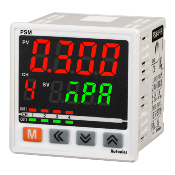
- Page 1 Communication Multi-CH Pressure Sensor Indicator PSM Series Thank you for purchasing an Autonics product. This user manual contains information about the product and its proper use, and should be kept in a place where it will be easy to access.
- Page 2 © Copyright Reserved Autonics Co., Ltd.
-
Page 3: Preface
Preface Preface Thank you for purchasing an Autonics product. Please familiarize yourself with the information contained in the Safety Precautions section before using this product. This user manual contains information about the product and its proper use, and should be kept in a place where it will be easy to access. -
Page 4: User Manual Guide
Visit our web site (www.autonics.com) to download a copy. The manual's content may vary depending on changes to the product's software and other unforeseen developments within Autonics, and is subject to change without prior notice. Upgrade notice is provided through out homepage. ... -
Page 5: Communication Protocol
Communication Protocol Communication Protocol PSM Series is accepted to Modbus RTU Protocol. Users should be aware that it does not support a broadcast command. © Copyright Reserved Autonics Co., Ltd. -
Page 6: User Manual Symbols
Failure to follow instructions can result in serious injury or death. Failure to follow instructions can lead to a minor injury or product damage. An example of the concerned feature's use. ※1 Annotation mark. © Copyright Reserved Autonics Co., Ltd. -
Page 7: Safety Precautions
Do not supply excessive power to the unit case or twist the unit case strongly. Failure to follow this instruction may result in product damage. The above specifications are subject to change and some models may be discontinued without notice. © Copyright Reserved Autonics Co., Ltd. - Page 8 Safety Precautions viii © Copyright Reserved Autonics Co., Ltd.
-
Page 9: Table Of Contents
2.5.1 Preset value setting [Func: 03/06/16, R/W: R/W] ........24 2.5.2 Integrated setting function group [Func: 03/06/16, R/W: R/W] ....26 2.5.3 Setting function group by each channel [Func: 03/06/16, R/W: R/W] ..28 © Copyright Reserved Autonics Co., Ltd. -
Page 10: Table Of Contents
Table of Contents © Copyright Reserved Autonics Co., Ltd. -
Page 11: Modbus Rtu Protocol
Response (Slave) Data Data Error check (CRC16) Slave address Function Byte count (000008 to (000010 to High 000001) 000009) 11 H 01 H 02 H CD H 01 H ## H ## H © Copyright Reserved Autonics Co., Ltd. -
Page 12: Read Input Status (Func 02-02H)
Response (Slave) Data Data Error check (CRC16) Slave address Function Byte count (100008 to (100010 to High 100001) 100009) 11 H 02 H 02 H CD H 01 H ## H ## H © Copyright Reserved Autonics Co., Ltd. -
Page 13: Read Holding Registers (Func 03-03H)
Response (Slave) Data Data Error check (CRC16) Slave address Function Byte count High High High 11 H 03 H 04 H 02 H 2B H 00 H 64 H ## H ## H © Copyright Reserved Autonics Co., Ltd. -
Page 14: Read Input Registers (Func 04-04H)
Response (Slave) Data Data Error check (CRC16) Slave address Function Byte count High Low High High 11 H 04 H 04 H 00 H 0A H 00 H 14 H ## H ## H © Copyright Reserved Autonics Co., Ltd. -
Page 15: Force Single Coil (Func 05-05H)
## H Response (Slave) Starting address Preset data Error check (CRC16) Slave address Function High High High 11 H 05 H 00 H 00 H FF H 00 H ## H ## H © Copyright Reserved Autonics Co., Ltd. -
Page 16: Preset Single Registers (Func 06-06H)
## H Response (Slave) Starting address Preset data Error check (CRC16) Slave address Function High High High 11 H 06 H 00 H 00 H 00 H 0A H ## H ## H © Copyright Reserved Autonics Co., Ltd. -
Page 17: Preset Multiple Registers (Func 16-10H)
(device) connecting with external devices such as PLC, Graphic Panel, except in the case of download that presets the minimum/maximum or basic value of parameter by Input specifications in PC Loader Program © Copyright Reserved Autonics Co., Ltd. -
Page 18: Exception Response-Error Code
E8 H 00 H 01 H ## H ## H Response (Slave) Error check (CRC16) Function Slave address Exception Code +80 H High 11 H 81 H 02 H ## H ## H © Copyright Reserved Autonics Co., Ltd. -
Page 19: Modbus Mapping Table
CH7 parameter - Same as above CH1's 007004(1B5B) 008001(1F40) to CH8 parameter - Same as above CH1's 008004(1F43) ※The only one of digital functions (Auto shift, Hold, Manual return for control output) set at ADDRESS 400053(0034). © Copyright Reserved Autonics Co., Ltd. -
Page 20: Read Input Status (Func 02) [Func: 02, R/W: R]
CH8 OUT1 indicator CH8 OUT1 indicator 0: OFF, 1: ON 100016(000F) CH8 OUT2 indicator CH8 OUT2 indicator Digital input 0: OFF, 1: ON 100017(0010) D-IN input D-IN input status terminal status 100018 to Reserved 100050 © Copyright Reserved Autonics Co., Ltd. -
Page 21: Read Input Register_1 (Func 04) [Func: 04, R/W: R]
300120(0077) Input status start address 0000 300121(0078) Input status quantity 300122(0079) Holding register start address 0000 300123(007A) Holding register quantity 300124(007B) Input register start address 0000 300125(007C) Input register quantity 300126 to Reserved 300200 © Copyright Reserved Autonics Co., Ltd. -
Page 22: Read Input Register_2 (Func 04) [Func: 04, R/W: R]
301042(0411) Disp1 Monitoring Display part 1 value ※ 3 301043(0412) Disp2 Monitoring Display part 2 value ※ 4 0: OFF, 1: ON CH1 OUT1 indicator OUT1/2 indicator per CH 301044(0413) 301045 to Reserved 301050 © Copyright Reserved Autonics Co., Ltd. - Page 23 0 or 1 Bit 8 5CH OUT1 Bit 9 5CH OUT2 Bit A 6CH OUT1 Bit B 6CH OUT2 Bit C 7CH OUT1 Bit D 7CH OUT2 Bit E 8CH OUT1 Bit F 8CH OUT2 © Copyright Reserved Autonics Co., Ltd.
-
Page 24: Write Multiple Registers (Func 16)
400011(000A) display pressure-(3×Min. _Low value display unit) LOW+(3×Min. display Hysteresis-Window HIGH comparison mode 400012(000B) unit)≤HIGH≤Max. display _High value pressure Min. display Automatic sensitivity pressure≤ST1≤Max. 400013(000C) setting mode_SV1 display pressure-1% of rated pressure © Copyright Reserved Autonics Co., Ltd. - Page 25 CH5 parameter - Same as above CH1's 404050(0FD1) 405001(1388) to CH6 parameter - Same as above CH1's 405050(13B9) 406001(1770) to CH7 parameter - Same as above CH1's 406050(17A1) 407001(1B58) to CH8 parameter - Same as above CH1's 407050(1B89) © Copyright Reserved Autonics Co., Ltd.
-
Page 26: Integrated Setting Function Group [Func: 03/06/16, R/W: R/W]
0: 1, 1: 2 400063(003E) Comm. stop bit Comm. RSwT 5 to 99: 05 to 99 400064(003F) response time COmW 0: ENA, 1: DISA 400065(0040) Comm. write LOCK 0: OFF, 1: LOC1, 2: LOC2 400066(0041) Lock © Copyright Reserved Autonics Co., Ltd. - Page 27 INIT 0: NO, 1: YES 400068(0041) reset 400069 to Reserved 400100 ※1: Manual return for freezer control output is displayed and settable for freezer pressure control mode and reset [rA-M] as manual reset [MAN]. © Copyright Reserved Autonics Co., Ltd.
-
Page 28: Setting Function Group By Each Channel [Func: 03/06/16, R/W: R/W]
0: Hold, 1: Reset function Low peak lPEK HOLD 400113(006E) 0: Hold, 1: Reset function 400114 to Reserved 400150 401101(044C) CH2 parameter - Same as above CH1's 401150(047D) 402101(0834) CH3 parameter - Same as above CH1's 402150(0865) © Copyright Reserved Autonics Co., Ltd. - Page 29 CH5 parameter - Same as above CH1's 404150(1035) 405101(13EC) to CH6 parameter - Same as above CH1's 405150(141D) 406101(17D4) to CH7 parameter - Same as above CH1's 406150(1805) 407101(1BBC) to CH8 parameter - Same as above CH1's 407150(1BED) © Copyright Reserved Autonics Co., Ltd.
- Page 30 * Dimensions or specifications on this manual are subject to change and some models may be discontinued without notice. MSB-PSMC1-V1.2-1904US...
Need help?
Do you have a question about the PSM Series and is the answer not in the manual?
Questions and answers