Autonics KRN100 Series User Manual
Hide thumbs
Also See for KRN100 Series:
- User manual (82 pages) ,
- Manual (17 pages) ,
- Product manual (3 pages)
Table of Contents
Advertisement
Quick Links
Advertisement
Table of Contents

Related Manuals for Autonics KRN100 Series


Summary of Contents for Autonics KRN100 Series
- Page 1 User Manual Recorder KRN100 Series MCR-KRN100U1-V1.1-2202US Thank you for purchasing an Autonics product. This user manual contains information about the product and its proper use, and should be kept in a place where it will be easy to access. www.autonics.com...
-
Page 2: Preface
Preface Preface Thank you very much for selecting Autonics products. Please familiarize yourself with the information contained in the Safety Considerations section before using this product. This user manual contains information about the product and its proper use, and should be kept in a place where it will be easy to access. -
Page 3: User Manual Guide
The manual's content may vary depending on changes to the product's software and other unforeseen developments within Autonics, and is subject to change without prior notice. We contrived to describe this manual more easily and correctly. However, if there are any ... -
Page 4: User Manual Symbols
Failure to follow instructions can result in serious injury or death. Failure to follow instructions can lead to a minor injury or product damage. An example of the concerned feature's use. Annotation mark. ※1 © Copyright Reserved Autonics Co., Ltd. -
Page 5: Safety Considerations
Failure to follow this instruction may result in fire or electric shock. Since Lithium battery is embedded in the product, do not disassemble or burn the unit. Failure to follow this instruction may result in fire. © Copyright Reserved Autonics Co., Ltd. - Page 6 If the jumper pin is placed improperly, it may result in product damage or malfunction. ※ The specifications and dimensions of this manual are subject to change without notice. ※Be sure to follow cautions written in the instruction manual and the technical descriptions (catalog, website). © Copyright Reserved Autonics Co., Ltd.
-
Page 7: Table Of Contents
Checking driver ..................34 Display ...................... 35 Initial booting screen ..................35 Screen layout ....................36 6.2.1 Status display ..................... 36 6.2.2 Virtual keyboard ..................39 6.2.3 Parameter setting display ................40 Operation ....................41 © Copyright Reserved Autonics Co., Ltd. -
Page 8: Table Of Contents
DI-□ Type (Select digital input □) ..............85 8.3.3 DI-□ Reset No (Reset alarm number) ............86 8.3.4 DI-□ Status (Operation status) ..............86 COMMUNICATION SETUP (Communication setting) ........87 8.4.1 Modbus Address (Communication address) ..........90 viii © Copyright Reserved Autonics Co., Ltd. - Page 9 RESERVATION SETUP (Reservation setting) ..........116 8.7.1 Reservation Type (Reservation record) ........... 116 8.7.2 Reservation Period (Reservation record period) ........117 8.7.3 Reservation Time (Reservation record time) ........... 118 FILE/MEMORY SETUP(File/Memory setting) ..........119 © Copyright Reserved Autonics Co., Ltd.
- Page 10 Boot logo image setting ................142 9.4.4 Backup data checking function ..............143 Maintenance ................... 145 10.1 Ink cartridge replacement ................145 10.2 Recording paper replacement ................ 146 Troubleshooting ..................149 11.1 Error message ....................150 © Copyright Reserved Autonics Co., Ltd.
-
Page 11: Overview
Space saving for installation with compact design (Rear length: 168mm) Supports total 27 kinds of input sensor Enables to order several type input card (weight, voltage, current, frequency, potential meter, etc) © Copyright Reserved Autonics Co., Ltd. -
Page 12: Component And Sold Separately
(the number of additional connectors depends of the input/output card.) 1.2.2 Accessory (1) I/O card SCM-38I SCM-US48I (USB/RS485 converter) (RS232C/RS485 converter) Appearances of SCM-38I (RS232C to RS485 converter) and SCM-US48I (USB to RS485 converter) are same. © Copyright Reserved Autonics Co., Ltd. -
Page 13: Ordering Information
4EA (KRN-AR4×1EA) ⑤Alarm Relay output 8EA (KRN-AR4×2EA) 12EA (KRN-AR4×3EA) None 3EA (KRN-24V3×1EA) ⑥Transmitter power output 6EA (KRN-24V3×2EA) 9EA (KRN-24V3×3EA) 12EA (KRN-24V3×4EA) None ⑦Communication output RS485/Ethernet/USB (KRN-COM×1EA) ⑧Power voltage 100-240VAC, 50/60Hz Standard panel mounting type ⑨Case © Copyright Reserved Autonics Co., Ltd. - Page 14 KRN100(Recorder): 1EA KRN-UI2(Universal input card): 5EA (universal input card 1EA is 2-channel and 5EA × 2-channel =10-channel) KRN-DI6(Digital input card): 1EA KRN-AR4(Alarm output card): 2EA KRN-COM(Communication output card): 1EA © Copyright Reserved Autonics Co., Ltd.
-
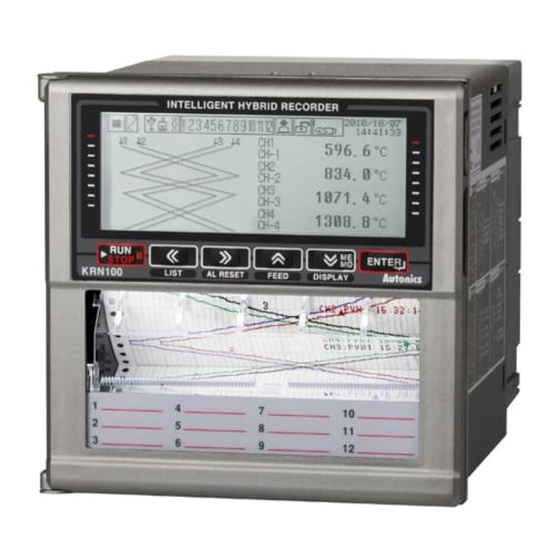
Page 15: Part Description
Using this key for entering setting mode (3 sec) and set value change mode. USB Host: Connects an USB memory. It recognizes max. 32Gbyte and if using cable, it is ⑤ available up to 1.5m. © Copyright Reserved Autonics Co., Ltd. - Page 16 Function key: Use this key to enter virtual keyboard in parameter setting. Press key, and Function key appears on lower screen as below figure. Press , or key as below Function key, it operates the appropriate Function key’s operation. © Copyright Reserved Autonics Co., Ltd.
-
Page 17: Back Side
= Total 4EA KRN-AT6 KRN-24V3 Total 4EA Slot(1 to 6) for connecting universal input card(KRN-UI2) ③ Power connecting part (100-240VAC, 50/60Hz) ④ ※ Above back side image is connected every otuput card to help your understand. © Copyright Reserved Autonics Co., Ltd. -
Page 18: Inside
Front cover of recording paper storage: Open recording paper guide for recording paper ③ replacement New recording paper storage: Storage part for new recording paper (1EA recording paper ④ is storable.) Back cover of recording paper storage ⑤ © Copyright Reserved Autonics Co., Ltd. -
Page 19: Specification
Insulated resistance Over 20MΩ (at 500VDC megger) Noise ±2kV the square wave noise (pulse width 1µs) by the noise simulator Time accuracy Within ±2min/year (enables to use up to 2100 year) © Copyright Reserved Autonics Co., Ltd. - Page 20 ※2. USB memory is included in the box. If you use USB memory you purchased separately, it could not be recognized. ※3. Environment resistance is rated at no freezing or condensation. ※4. The weight includes packaging. The weight in parenthesis is for unit only. © Copyright Reserved Autonics Co., Ltd.
-
Page 21: I/O Card
※Recommended to use shield cable over AWG24 RS485 Communi EEPROM life cycle: ≈ 1,000,000 operations (Erase / Commu cation KRN- nication Write) output output Ethernet IEEE802.3(U), 10/100 BASE-T(Modbus TCP) card ※ 3 USB V2.0 Full Speed(Device Control) Device ※ 4 © Copyright Reserved Autonics Co., Ltd. - Page 22 ※ It is recommended to use shield cable to decrease noise when sensor input cable is longer. If connecting or disconnecting input/output card when power is ON, it may cause malfunction. To connect or disconnect input/output card, you must turn OFF the power. © Copyright Reserved Autonics Co., Ltd.
-
Page 23: Input Specification And Measuring Range
※3. Russian type L type temperature sensor is divided from general purpose L type. When changing input type to voltage (over ±2V) or current, set the jumper pin of KRN-UI2 (universal input card). Its factory default is tempeature sensor input. Refer to the ‘4.2 I/O card’. © Copyright Reserved Autonics Co., Ltd. -
Page 24: Dimensions
3 Dimensions Dimensions (1) KRN100 (Unit: mm) (2) Panel cut-out ※ Use panel which is 2 to 8mm thickness. © Copyright Reserved Autonics Co., Ltd. - Page 25 3 Dimensions (3) Bracket © Copyright Reserved Autonics Co., Ltd.
-
Page 26: Connection
Slot Description 1 to 6 Connects universal input card (KRN-UI2). Connect digital input card (KRN-DI6), alarm output card (KRN-AR4, KRN-AT6), and 7 to 10 transmitter power output card (KRN-24V3). Connects communication output card (KRN-COM). © Copyright Reserved Autonics Co., Ltd. -
Page 27: I/O Card
500 V. Alarm output card Alarm output card [KRN-AR4(relay output)] [KRN-AT6(transistor output)] ※AL1,2,3 and AL4,5,6 are isolated. Transmitter power output card Communication output card [KRN-COM] [KRN-24V3] ※24V output of 3EA is isolated individually. © Copyright Reserved Autonics Co., Ltd. - Page 28 Jumper pin Input specification Input break alarm 0 to 20mA, 4 to 20mA Enables only 4 to 20mA ① TC, RTD, ±60mV, ±200mV Enables ② ±2V, 1 to 5V, ±5V, -1 to 10V Disables ③ © Copyright Reserved Autonics Co., Ltd.
-
Page 29: Installation
You should warm-up this unit over 30 min. to acquire accurate data before using it. At the place where temperature and humidity is fluctuated excessively, recording paper color may be changed. © Copyright Reserved Autonics Co., Ltd. -
Page 30: Installation
Bracket mounting Install KRN100 on the processed panel as panel cut-out diagram. Mount fixing brackets on upper/lower parts. Tighten fixing brackets on upper/lower parts to fix on the panel with phillips screwdriver (+). (Torque: 0.4N•m) © Copyright Reserved Autonics Co., Ltd. -
Page 31: Additional I/O Card Connection
To connect I/O card additionally, turn OFF the power of KRN100. Remove the proper slot cover to insert I/O card with flat-head screwdriver or knife. Insert I/O card to the proper slot and turn ON the power of KRN100. © Copyright Reserved Autonics Co., Ltd. -
Page 32: Usb To Serial Driver
Supporing operation system for USB to Serial driver is Windows XP, VISTA(32/64bit), 7 (32/64bit).) 5.3.1 Driver installation Visit our homepage www.autonics.com and downlaod 'KRN100_USB_Serial_Drivers’. Unzip this file to the desired folder. Connect KRN100 USB port of communication output card(KRN-COM) and PC USB port with USB cable (A-Mini 5P, 1.5m). - Page 33 Click ‘Browse’ and select the folder which has 'KRN100_USB_Serial_Drivers’ and click ‘OK’. If hardware compatibility message appears, click ‘Continue Anyway’ and it processes the next. At ‘Completing the Found New Hardware Wizard’, click ‘Finish’ and driver installation is complete. © Copyright Reserved Autonics Co., Ltd.
-
Page 34: Checking Driver
To check the driver, right click 'My computer' and select 'Properties' on pop-up menu. 'System Properties' dialog appears. Select ‘Hardware’ tab and click 'Device Manager'. ‘Device Manager’dialog appears. Check ‘Ports(COM & LPT)’ - 'KRN100 USB To Serial Converter (COMx)'. © Copyright Reserved Autonics Co., Ltd. -
Page 35: Display
Delete log data file. For more information, refer to ‘8.8.4 Memory Clear (Delete memory)’. Screen for error of inner system memory Above this figure, if there is error of inner system memory, KRN100 cannot operate normally. Please contact us. Autonics service center: +82-32-820-2356~7 © Copyright Reserved Autonics Co., Ltd. -
Page 36: Screen Layout
Record memory status Marks it storage capacity of record memory in icon digital mode or graph mode. No recording paper Marks it for no recording paper. Please replace icon new recording paper. ※ 1 © Copyright Reserved Autonics Co., Ltd. - Page 37 ※1. If there is no recording paper, icon flashes. After replacing recording paper, P.END BACKUP PRINT screen as below is activated. Backup data recording function by P.END is same as RECORD BACKUP. Backup Data List cannot be changed. © Copyright Reserved Autonics Co., Ltd.
- Page 38 6 Display Starting print by P.END Backup, it prints the data but backup data file date, file name, and backup record starting line. © Copyright Reserved Autonics Co., Ltd.
-
Page 39: Virtual Keyboard
Moves digit to select character of virtual keyboard Enters set characters ※1. Enterable characters are as below. English capital letters English small letters Special character ※2. Screen of Function key using © Copyright Reserved Autonics Co., Ltd. -
Page 40: Parameter Setting Display
When entering parameter setting group, setable parameter setting groups are displayed. At parameter setting group, press key to enter parameter setting. For more information of parameter detail setup, please refer to ‘8 Parameter detail setup’. © Copyright Reserved Autonics Co., Ltd. -
Page 41: Operation
7 Operation Operation Screen display 7.1.1 Measuring value display KRN100 displays measuring value as trend graph, bar graph, and digital number display(1 channel, 8 channels, 12 channels). You can select one by key. © Copyright Reserved Autonics Co., Ltd. - Page 42 Display of 1 channel digital number: Displays 1 channel per 1 screen with big font size. It has high visibility. Display of 8 channels digital number: Displays 8 channels per 1 screen. Display of 12 channels digital number: Displays 12 channels (all channels) per 1 screen. © Copyright Reserved Autonics Co., Ltd.
-
Page 43: Channel Switch
7.1.2.1 Auto channel switch A screen displays 4 channels and automatically switches other screens by 3 sec period. (1) Trend graph (2) Bar graph © Copyright Reserved Autonics Co., Ltd. - Page 44 If you want to change manual channel switch mode, press key or key. You can switch/select the to-be displayed channel by pressing key or key. In manual channel switch mode, press key to change to auto channel switch mode. © Copyright Reserved Autonics Co., Ltd.
-
Page 45: Special Operation For Record
It records current time (hh:mm:ss) and display value of each channel as digital number on recording paper. It also displays ‘M’ which means the recording by memo at front of current time. © Copyright Reserved Autonics Co., Ltd. -
Page 46: Parameter Setting Group
Press OK ( ) key or Cancel ( ) key. Cancel: Moves to upper parameter after not saving the setting. OK: Moves to upper parameter after saving the setting. © Copyright Reserved Autonics Co., Ltd. -
Page 47: Quick Menu
[FILE/MEMORY SETUP]- Call USB COPY USB COPY window [USB Memory Copy/Move] QUICK MENU [4] [USER/INFORMATION SETUP]- UPGRADE Call upgrade window [Firmware Upgrade] CANCEL Cancel the settings SAVE Save the setting of QUICK MENU[1] to [4]. © Copyright Reserved Autonics Co., Ltd. - Page 48 ) key at QUICK MENU[4] and save the settings. It returns to RUN mode. In case of CH1, recording as input type=TC-U, low-limit input value=300, standrad record speed= 240mm/h Press the key in RUN mode to enter QUICK MENU. © Copyright Reserved Autonics Co., Ltd.
- Page 49 Press the NEXT( ) key once and it moves to QUICK MENU [4]. Press the SAVE( ) key to save the settings of QUICK MENU [1] to [4] and it returns to RUN mode. © Copyright Reserved Autonics Co., Ltd.
- Page 50 7 Operation © Copyright Reserved Autonics Co., Ltd.
-
Page 51: Parameter
7 Operation 7.3.3 Parameter © Copyright Reserved Autonics Co., Ltd. - Page 52 7 Operation ※Dot parameters may or may not appear, depending on the other parameter setting. © Copyright Reserved Autonics Co., Ltd.
-
Page 53: Parameter Detail Setup
Special Function (Special function) None Analog: Linear ↔ Square ↔ Root ↔ Two Unit Two Unit (Display the degree of a 1 to 35 vacuum, static pressure) Reference Channel (Reference channel) None ↔ CH□-S□UI-□ © Copyright Reserved Autonics Co., Ltd. - Page 54 High Range & Graph Scale (Upper limit input value Input Type(input type) ▶ and graph scale value) parameter, Low Scale(Analog lower limit scale value) High Scale(Analog upper limit scale value) Special Function (Input special function) parameters’ set values are reset. © Copyright Reserved Autonics Co., Ltd.
-
Page 55: Select Ui Card (Select Universal Input Card)
High Range & Graph Scale (Upper limit input value and Low Range & Graph Scale (Lower limit input value and graph scale value) graph scale value) Setting range: None/CH□-S□UI-□ Factory default: CH Select © Copyright Reserved Autonics Co., Ltd. -
Page 56: Lcd/Paper Record (Display And Record Measuring Value)
If the set is ‘None’, record zone is full width(100mm) of recording paper. Setting range: None, 1 ↔ Zone n (n: set value of Divide Zone (Record zone division)) Factory default: None © Copyright Reserved Autonics Co., Ltd. -
Page 57: Tag Name (Channel Name)
For more details, please refer to ‘2.3 Input specification and measuring range’. For jumper pin setting of universal input card (KRN-UI2) by inpust specification, refer to ‘4.2 I/O card’. Setting range: Refer to ‘2.3 Input specification and measuring range’ Factory default: TC-K © Copyright Reserved Autonics Co., Ltd. -
Page 58: Range/Scale Point (Decimal Point)
In case analog(current, voltage): 0 ↔ 0.0 ↔ 0.00 ↔ 0.000 ↔ 0.0000 Factory default: 0.0 If you want high accuracy display, select ‘0.0(decimal point)’. If you want to stable accuracy display, select ‘0 (no dicimal point)’. © Copyright Reserved Autonics Co., Ltd. -
Page 59: Display/Temp Unit (Display Unit/Temperature Unit)
You can use user-defined unit image by selecting user-defined (User0 to User9) unit. Please refer to ‘9.4.2 User unit setting’. The unit with multiplier such as kg/cm or complicated unit may be printed in low quality due to low print resolution. © Copyright Reserved Autonics Co., Ltd. -
Page 60: High/Low Range & Graph Scale(Upper/Lower Limit Input Value And Graph Scale Value)
Setting range: Min. value of input range to upper limit graph scale value (High Graph Scale) – F.S. 5% When TC-K input range is -200.0 to 1350℃, setting range is -200.0 to 1272.5℃. Factory default: -200.0 © Copyright Reserved Autonics Co., Ltd. -
Page 61: Low Scale/High Scale (Lower Limit/Upper Limit Scale Value)
You can change display value about min./max. input value of measuring value. In case input specification is 0-20mA Set Low Scale (Lower limit scale value) = 0.0, High Scale (Upper limit scale value) = 10.0, 20.0, 30.0, -20.0. © Copyright Reserved Autonics Co., Ltd. - Page 62 Setting range: -99999 to 99999 ↔ -9999.9 to 9999.9 ↔ -999.99 to 999.99 ↔ - 99.999 to 99.999 ↔ -9.9999 to 9.9999 (Depending on Scale Point setting, the range is different.) Factory default: - © Copyright Reserved Autonics Co., Ltd.
-
Page 63: Special Function (Special Function)
Input Type (input specification) is set as 0-20mA, 4-20mA.) Factory default: None Below graph’s patterns are liner, root, square for analog input. Lower limit input value: -5V, Upper limit input value: +5V, Lower limit scale: -1000, Upper limit scale: 1000 © Copyright Reserved Autonics Co., Ltd. - Page 64 2V, display value is approx. 673.32. Input value−Lower limit input value Upper limit input value−Lower limit input value Lower limit scale ) + Lower limit scale 673.32 = � × 2000 − 1000 © Copyright Reserved Autonics Co., Ltd.
- Page 65 (mA) -760mmHg to 1kg/cm 12.130 -760mmHg to 5kg/cm 6.740 -760mmHg to 10kg/cm 5.498 -760mmHg to 15kg/cm 5.031 -760mmHg to 20kg/cm 4.786 -760mmHg to 25kg/cm 4.635 -760mmHg to 30kg/cm 4.533 -760mmHg to 35kg/cm 4.459 © Copyright Reserved Autonics Co., Ltd.
-
Page 66: Reference Channel (Reference Channel)
Reference Channel (Reference channel) In case Input Type(Input specification) is temperature sensor(thermocouple, RTD), set Special Function(special function) as Difference to set reference channel. Setting range: None / CH □-S□UI-□ Factory default: - © Copyright Reserved Autonics Co., Ltd. -
Page 67: Input Bias(Error Correction)
0.00 10.00 0.500 0.00 to 5.00 0.00 5.00 1.000 0.00 10.00 1.000 0.00 to 10.00 0.00 10.00 1.000 0.00 10.00 1.500 0.00 to 15.00 0.00 15.00 1.000 © Copyright Reserved Autonics Co., Ltd. - Page 68 10.00 0.00 0.500 10.00 to 5.00 10.00 5.00 1.000 10.00 0.00 1.000 10.00 to 0.00 10.00 0.00 1.000 10.00 0.00 1.500 10.00 to -5.00 10.00 -5.00 1.000 © Copyright Reserved Autonics Co., Ltd.
-
Page 69: Record Method (Data Storage Method)
Input digital filter uses moving average method (Moving Average Filter). It does not affet to display period but display value may be different with input value. Setting range: None ↔ Moving Factory default: None © Copyright Reserved Autonics Co., Ltd. -
Page 70: Filter Counter (The Number Of Digital Filter)
Display values of D1, D2, D3 is the initial operation before averaging 4 sampling values. D4 = , D5 = S3 + S4 + S5 + S6 S4 + S5 + S6 + S7 D6 = , D7 = S5 + S6 + S7 + S8 D8 = © Copyright Reserved Autonics Co., Ltd. -
Page 71: Burnout Action (Display Setting For Break)
According to circuit structure, when thermocouple(Thermocouple) temperature sensor, RTD(RTD) temperature sensor’s A-B terminal or voltage input ±60mV, ±200mV input is break, it displays Down Scale. When RTD(RTD) temperature sensor’s B-B' terminal input is break, it displays Up Scale. © Copyright Reserved Autonics Co., Ltd. -
Page 72: Alarm Setup (Alarm Setting)
(alarm output card), AL1 to AL4 are N.O. N.O.↔N.C. Alarm-□ Status(Relay and transistor activated. When connecting transistor type KRN-AT6 output method) ※1 N.O. N.O.↔N.C. (alarm output card), AL1 to AL6 are activated. N.O. N.O.↔N.C. N.O. N.O.↔N.C. © Copyright Reserved Autonics Co., Ltd. -
Page 73: Select Ui Card (Select Universal Card Input)
(Alarm□ ON delay time) Alarm□ OFF Delay Alarm□ Alarm No (Alarm□ OFF delay time) (Alarm□ output relay number) Setting range: No Select/CH□-S□UI-□(Activated connected universal input(2 channels per input card) Factory default: CH Select © Copyright Reserved Autonics Co., Ltd. -
Page 74: Alarm□ Type(Alarm□ Operation Mode)
Alarm is automatically cleared when recording paper is replaced (in case of general alarm). P.END BACKUP PRINT window is activated P.END recording and it is available to output backup data. paper alarm © Copyright Reserved Autonics Co., Ltd. - Page 75 [Alarm sign] Name Alarm sign Absolute value upper limit alarm ▲ Absolute value lower limit alarm ▼ Deviation upper limit alarm △ Deviation lower limit alarm ▽ Input break alarm No recording paper © Copyright Reserved Autonics Co., Ltd.
-
Page 76: Alarm□ Ref Channel(Alarm□ Reference Channel)
ON. This parameter is activated when Alarm□ Type(Alarm operation mode) is set as deviation upper limit alarm(DV.Hi) or deviation lower limit alarm(DV.Lo). Setting range: None / CH□-S□UI-□ Factory default: - © Copyright Reserved Autonics Co., Ltd. -
Page 77: Alarm□ Option(Alarm□ Option)
At the next alarm output ON, alarm output operates normally. Alarm□ Type(Alarm□ operation mode): PV.Lo (Absolute value lower limit alarm) Alarm□ Value(Alarm□ set value): 90 Alarm□ Hysteresis(Alarm□ hysteresis): 5 Alarm□ Option(Alarm□ option): StBy(Standby sequence) © Copyright Reserved Autonics Co., Ltd. -
Page 78: Alarm□ Value(Alarm□ Set Value)
Set alarm set value based on alarm output operation mode, it executes alarm operation. Setting range: Using set input from Input Type(Input specification)/within display range Factory default: Alarm1 value: 1350.0, Alarm2 Value to Alarm4 Value: - © Copyright Reserved Autonics Co., Ltd. -
Page 79: Alarm□ Hysteresis(Alarm□ Hysteresis)
The below graph is when Alarm□ Type(Alarm□ operation mode) is set as absolute value upper limit alarm, Alarm□ Value(Alarm□ set value) is set as 200, and Alarm□ Hysteresis(Alarm□ hysteresis) is set as 10. © Copyright Reserved Autonics Co., Ltd. -
Page 80: Alarm□ On/Off Delay(Alarm□ On/Off Output Delay Time)
Alarm OFF Delay channel display is hold), if it is still alarm reset condition, alarm output turns OFF. (Alarm ON channel resets the display.) Setting range: 0 to 3600 Factory default: 0s © Copyright Reserved Autonics Co., Ltd. -
Page 81: Alarm□ Alarm No(Alarm□ Output Alarm Number)
Select alarm output card(KRN-AR4, KRN-AT6) to set output type (Normally Open, Normally Closed) of alarm output. In front of output card name, relay or transistor abbreviation is displayed for easy to know connected module type when selecting output card. © Copyright Reserved Autonics Co., Ltd. -
Page 82: Alarm-□ Status(Relay And Transistor Output Method)
Relay and transistor type output is basically fixed as Normally Opened method and H/W when power is ON. Therefore, KRN100 takes booting time max. 20sec and maintains Normally open status. In case of RUN mode after booting, it maintains use-defined output type; Normally Open or Normally Closed. © Copyright Reserved Autonics Co., Ltd. -
Page 83: Digital Input Setup(Digital Input Setting)
DI-□ Reset No (Reset alarm number) None ↔ ALL ↔ S□AL-□ DI-□ Status (Operation status) Edge ↔ Level ※Shaded parameters are affected by set value of other parameters. Please refer to specific descriptions of each parameter. © Copyright Reserved Autonics Co., Ltd. -
Page 84: Select Di Card (Select Digital Input Card)
ON. Channel name is as below. Slot number Setting range: S7DI ↔ S8DI ↔ S9DI ↔ S10DI Factory default: Automatically set S9DI: This means connected digital input card on 9th slot © Copyright Reserved Autonics Co., Ltd. -
Page 85: Di-□ Type (Select Digital Input □)
RUN mode. This is available in record stop state by reservation record. Setting range: None ↔ Run ↔ Memo ↔ ListOut ↔ Speed ↔ Alarm Reset Factory default: None © Copyright Reserved Autonics Co., Ltd. -
Page 86: Di-□ Reset No (Reset Alarm Number)
If even one Level is set, DI-□ Status’s overlap setting to Level or setting to Edge is not available. In case DI-□ Status(operation status) is Edge: You can execute to start/stop recording with front key. In case DI-□ Status(operation status) is Level: You cannot execute to start/stop recording with front key. © Copyright Reserved Autonics Co., Ltd. -
Page 87: Communication Setup (Communication Setting)
DAQMaster program or to use the related Modbus program, please refer to user manual for communication. Visit our homepage (www.autonics.com) to download DAQMaster program, and user manual for communication. Move to COMMUNICATION SETUP with... - Page 88 Shield Twist Pair over AWG24, characteristic impedance RS485 communication 100Ω, capacity component 50pF/m cable length max. 1km Ethernet communication Over CAT5E, cable max. length: 100m USB Device communication Single cable built-in ferrite core within 1.5m © Copyright Reserved Autonics Co., Ltd.
- Page 89 For using terminating resistance, turn ON only terminal resistance of recoder on end of connected communication line (Enables to set using terminating resistance in communication set function), and also turn ON terminal resistance of connected communication to PC. © Copyright Reserved Autonics Co., Ltd.
-
Page 90: Modbus Address (Communication Address)
Setting range: Enable ↔ Disable Factory default: Enable 8.4.3 Baud Rate (Baud rate) Designate baud rated. Setting range: 2400 ↔ 4800 ↔ 9600 ↔ 19200 ↔ 38400 (unit: bps) Factory default: 9600 © Copyright Reserved Autonics Co., Ltd. -
Page 91: Parity Bit (Communication Parity Bit)
Desigante wheter using terminating resistance . You do not need to external terminating resistance (120Ω) because KRN100 is enable to use terminating resistance by parameter setting. Setting range: Enable ↔ Disable Factory default: Disable © Copyright Reserved Autonics Co., Ltd. -
Page 92: Response Wait Time (Communication Response Wait Time)
Set whether changing the set value of KRN100 parameter by RS485 communication. To read the set value of each parameter is available regardless of the communication write enable/disable setting. Setting range : Enable ↔ Disable Factory default : Enable © Copyright Reserved Autonics Co., Ltd. -
Page 93: Ethernet Port (Use Ethernet Communication)
The following is based on Windows XP. First of all connect Ethernet slot of KRN-100 communication output card (KRN-COM) and LAN slot of PC with LAN cable. Execute Start > Run to check IP address of PC. © Copyright Reserved Autonics Co., Ltd. - Page 94 Set KRN100 Ethernet Port(Use Ethernet communication) as ‘Enable’ at COMMUNICATION SETUP (Communication setting) of KRN100. Set IP Address(IP address) as installation environment. KRN100 IP Address 192.168.1.1 192.168.1.2 Subnet Mask 255.255.255.0 Default Gateway 192.168.1.1 IP address set for Modbus TCP communication is complete. © Copyright Reserved Autonics Co., Ltd.
-
Page 95: Ip Address (Ip Address)
Setting range: 0.0.0.0 to 255.255.255.255 Factory default: - 8.4.13 Default Gateway (Default gateway) Designate IP address to connect IP router directly. Setting range: 0.0.0.0 to 255.255.255.255 Factory default: - © Copyright Reserved Autonics Co., Ltd. -
Page 96: Ethernet Com Write (Ethernet Communication Write)
Set whether changing the set value of KRN100 parameter by USB communication. To read the set value of each parameter is available regardless of the communication write enable/disable setting. Setting range: Enable ↔ Disable Factory default: Enable © Copyright Reserved Autonics Co., Ltd. -
Page 97: Record Setup (Record Setting)
1 to 25 Pen6 (Brown) ON Time (Ink cartridge point delay time) 1 to 25 ※ Shaded parameters are affected by set value of other parameters. Please refer to specific descriptions of each parameter. © Copyright Reserved Autonics Co., Ltd. -
Page 98: Record Mode (Recode Mode)
(Print/Record period) and also records current date (Year-Month-Day) and time in every 00:00:00. You can record digital memo manually by front key (press key for 3 sec), or digital input terminal. Setting range: Graph ↔ Digital Factory default: Graph © Copyright Reserved Autonics Co., Ltd. -
Page 99: Digital Print Type(1 Line Record Channel During Numeric Recording)
TwoCH, it also records one channel’s error message and occurring alarms in 4 alarms. Print form is as below. For the information about alarm abbreviations, please refer to ‘8.2.3 Alarm□ Type(Alarm□ operation mode)’. For the information about error abbreviations, please refer to ‘11.1 Error message’. © Copyright Reserved Autonics Co., Ltd. -
Page 100: Standard Speed (Standard Record Speed)
Option Speed(Pption record speed) is also changed as same as the set value of Standard Speed. (Option Speed should not be lower than Standard Speed.) Setting range: 10 ↔ 20 ↔ 40 ↔ 60 ↔ 120 ↔ 240 mm/h Factory default: 20mm/h © Copyright Reserved Autonics Co., Ltd. -
Page 101: Memo Period (Digital Memo Period)
Digital memo period setting time when record channel is 3 to 4CH Record 1 min 5 min 10 min 15 min 30 min 1 hour 2 hour 3 hour 4 hour 8 hour 16 hour 24 hour speed ○ ○ ○ ○ ○ © Copyright Reserved Autonics Co., Ltd. - Page 102 Digital memo period setting time when record channel is 11 to 12CH Record 1 min 5 min 10 min 15 min 30 min 1 hour 2 hour 3 hour 4 hour 8 hour 16 hour 24 hour speed ○ ○ ○ ○ ○ ○ © Copyright Reserved Autonics Co., Ltd.
-
Page 103: Divide Zone (Record Zone Division)
If there is too many division for record zone, record value check accuracy is low. Setting range: None, 2 to 12 Factory default: None Set value of record zone division: None Set value of record zone division : 5 © Copyright Reserved Autonics Co., Ltd. -
Page 104: Standard Period (Standard Record Period)
3 to 4 02m 00s to 99m 59s 9 to 10 05m 00s to 99m 59s 5 to 6 03m 00s to 99m 59s 11 to 12 06m 00s to 99m 59s Factory default: - © Copyright Reserved Autonics Co., Ltd. -
Page 105: Listing Language (Language For List Output)
8 Parameter detail setup 8.5.9 Listing Language (Language for list output) Desigante recorded langauge when list output. Language Example of recording English Korea Setting range: English ↔ Korea Factory default: English © Copyright Reserved Autonics Co., Ltd. -
Page 106: Alarm Speed (Alarm Record Speed)
Maintains record status of before power OFF (recording or stop recording). Run(Record) Operates recording when power is ON. Stop(Stop recording) No recording when power is ON. Setting range: Hold↔Run↔Stop Factory default: Hold © Copyright Reserved Autonics Co., Ltd. -
Page 107: Run Status (List Printing At Start Recording)
After printing list with 240mm/h record speed, it processes record with changed set record speed. Please refer to List Out Option(List record option) for the set list item. Setting range: ON / OFF Factory default: OFF © Copyright Reserved Autonics Co., Ltd. -
Page 108: List Out Option (List Record Option)
Setting range: Standard↔Option Factory default: Standard List is printed with max. record speed (240mm/h). Depending on the number of channel, it may take long time. Therefore, be sure this when printing the list. © Copyright Reserved Autonics Co., Ltd. -
Page 109: Zone Dot Line Distance (Dot Line For Zone Division)
Designate the interval for printing channel number of each graph as below figure. It is activated when Record Mode(Record mode) is set as ‘Graph’. Setting range: No Print to 100.0mm(Set by 10mm interval) Factory default: 20.0mm © Copyright Reserved Autonics Co., Ltd. -
Page 110: Start Line Print (Start Line When Starting Record)
During Range printing, the other data except graph is not recorded within pritted range. Be sure that if there is too many channel numbers or if Range Print Time interval is too short with low speed, various information about channel is not printed at Range print zone. © Copyright Reserved Autonics Co., Ltd. -
Page 111: Penx(Color) On Time (Ink Cartridge Point Delay Time)
The higher the value, the shorter the life of the ink cartridge. Setting range: 1 to 25 Factory default: 13 The setting values are maintained even after initialization in the [FILE/MEMORY SETUP-Load Set File] menu. This menu cannot be set by communication. © Copyright Reserved Autonics Co., Ltd. -
Page 112: System Setup (System Setting)
Device Name (Device name) Designate user defined KRN100 name. It supports up to 16 characeters with English capital letters, English small letters, and special letter. Setting range: 16 characters Factory default: KRN100 Recorder © Copyright Reserved Autonics Co., Ltd. -
Page 113: Date/Time (Date/Time)
When you set Summer Time, it adds current time and 1 hour and displays ‘(S)’ mark in front of the date and time on LCD screen or in front of the date on recording paper. Setting range: Disable ↔ Enable Factory default: Disable © Copyright Reserved Autonics Co., Ltd. -
Page 114: Summer Time Period (Summer Time Period)
When connecting 1 to 2 universal input card(KRN-UI2): 25↔125↔250ms When connecting 3 to 6 universal input card(KRN-UI2): 125↔250ms Factory default: 125ms Min. sampling period for TC-R, U, S, T sensors is 50ms. © Copyright Reserved Autonics Co., Ltd. -
Page 115: Log Speed (Save Period)
Designate LCD backlight ON method. If you set as ‘Always’, it maintins ON status, as ‘Temp’, it maintains only for 30 sec when key is input. Setting range: Always ↔ Temp Factory default: Temp © Copyright Reserved Autonics Co., Ltd. -
Page 116: Reservation Setup (Reservation Setting)
(1) Repeat(Repeat ON/OFF) From start recording date to end recording date, it records data at from the set start time to the set end time. End time must be later than Start time. © Copyright Reserved Autonics Co., Ltd. -
Page 117: Reservation Period (Reservation Record Period)
‘Repeat(Repeat ON/OFF)’ or ‘Single(Single ON/OFF)’, it is activated to designate Start Date(Start date) and End Date(End date). Setting range: 2000 / 01 / 01 to 2099 / 12 / 31 Factory default: -- © Copyright Reserved Autonics Co., Ltd. -
Page 118: Reservation Time (Reservation Record Time)
Setting range: 0/ 00/ 00 to 23/ 59/ 59 Factory default: -- If reservation record(Reservation record) is set and during reservation recording, digital input is not available as RUN mode. In stopping recording status by reservation record, it is available. © Copyright Reserved Autonics Co., Ltd. -
Page 119: File/Memory Setup(File/Memory Setting)
Cancel ↔ All Clear Clear ... USB LogData Save (USB storage function) Enable ↔ Disable Disable Memory Save Option (Memory storage option) Overwrite ↔ Stop Stop USB Memory Copy/Move (Move/Copy data) USB Copy/Move ... © Copyright Reserved Autonics Co., Ltd. -
Page 120: Load Set File (Open Parameter Setting File)
Saves current set parameter set value to User1.pms to User5.pms file of inner memory. In case of empty file, it displays gray. Setting range: None ↔ User1.pms to User5.pms, User1.pms(USB) to User5.pms(USB) Factory default: Select … © Copyright Reserved Autonics Co., Ltd. -
Page 121: Memory Status (Memory Capacity)
Memory Clear (Delete memory) Delete the saved log data on system memory. Current saving backup data is not deleted when deleting backup data. Setting range: Cancel ↔ All Clear Factory default: Clear … © Copyright Reserved Autonics Co., Ltd. -
Page 122: Usb Logdata Save (Usb Storage Function)
The number of backup data files in the USB memory should be less than 200. If the number exceeds 200, the device may malfunction. Be sure to back up the data in the USB memory periodically. © Copyright Reserved Autonics Co., Ltd. -
Page 123: Memory Save Option (Memory Storage Option)
Stops backup data. Stop(Stop saving) It does not save Backup data. Even though new recording paper is replaced, output function for backup data does not operate. Setting range: Overwrite ↔ Stop Factory default: Stop © Copyright Reserved Autonics Co., Ltd. -
Page 124: Usb Memory Copy/Move (Move/Copy Data)
Setting range: (For the desired file) Copy to USB Memory, Move to USB Memory, Delete File Factory default: USB Copy/Move ... Copy(Move) to USB Memory Into Directory File Information © Copyright Reserved Autonics Co., Ltd. -
Page 125: User Information Setup(User Information Setting)
Change Admin Password (Change password by 0000 to 9999 administrator) User Lock (Change user authority) OFF ↔ LOCK1 ↔ LOCK2, ↔ LOCK3 Information (Check system information) Display ... Automatically Firmware Upgrade (Firmware upgrade) display © Copyright Reserved Autonics Co., Ltd. -
Page 126: Password (Password Mode)
Password mode setting: Disable → Enable is available without authority. But Enable → Disable changing is only available by administrator’s authority. Enter the set password at Login Admin to change the mode. In administrator lock state, when power turns OFF/ON, it changes user lock mode. © Copyright Reserved Autonics Co., Ltd. -
Page 127: Login Admin (Administrator Log In)
8.9.3 Change Admin Password (Change password by administrator) Change the previous password. Changing password is able only when login status as administrator. Setting range: 4 digit number Factory default: - © Copyright Reserved Autonics Co., Ltd. -
Page 128: User Lock (Change User Authority)
If connected and displayed card on slot and actaul connected card is inconsists, check the connect status of card and re-supply power. If it is not recognized even though re-supplying power, please contact our service center. Autonics service center: +82-32-820-2356~7 © Copyright Reserved Autonics Co., Ltd. -
Page 129: Firmware Upgrade (Firmware Upgrade)
Factory default: Automatically set Firmware upgrade Visit our homepage (www.autonics.com) to download ‘KRN100 firmware file (krn100.fwu)’. Copy the downloaded firmware file to an USB memory’s loot (top) directory and connect an USB memory to KRN100. Check that firmware is recognized on "USERINFORMATION SETUP -Firmware Upgrade"... - Page 130 After completing firmware upgrade and OFF/ON the power, if KRN100 displays booting screen and does not operate normally, it may have damage to the inner firmware during firmware upgrade. It is required to repair. Please contact our service center. Autonics service center: +82-32-820-2356~7 © Copyright Reserved Autonics Co., Ltd.
-
Page 131: Record Backup_ Setup (Backup Data Record Setting)
In graph mode, record speed is changed by Standard speed, Alarm, or Option Speed. Backup data is printed with Standard speed. Therefore, original printout and backup printout in graph mode may be different. © Copyright Reserved Autonics Co., Ltd. -
Page 132: Record Backup (Backup Data Record)
You can check saved Backup Data List(Backup data list). Backup Data is sorted automatically according to the recently occuring order. For the information of file selection of backup data list, please refer to ‘8.10.6 Select Print Mode (Backup data recording mode setting)’. © Copyright Reserved Autonics Co., Ltd. -
Page 133: Start Date And Time (Start Time For Data Storage)
Setting range Date: yyyy/ mm/ dd, Time: hh: mm :ss Factory default: 0000/00/00 00:00:00 8.10.5 Backup Print Mode (Backup data record mode) You can check record mode of current saved backup data. © Copyright Reserved Autonics Co., Ltd. -
Page 134: Select Print Mode (Backup Data Recording Mode Setting)
USB are also display. (If backup data is not designated or does not exist, it displays "File Not Found!!".) 3rd Select the desired file in Basckup Data List and press key and menu is displayed. (Marked ‘*’ files displays currently saving file.) © Copyright Reserved Autonics Co., Ltd. - Page 135 To move desired date folder, press key at the selected folder and menu screen is activated. Select 'Into Directory' in this menu, it moves to inner folder. Below screen shows inner folder and saved files. © Copyright Reserved Autonics Co., Ltd.
-
Page 136: Daqmaster
DAQMaster provides graph user interface (GUI) for easy and convenient integrated several products’ parameter setting and data monitoring. Visit our homepage (www.autonics.com) to download ‘DAQMaster user manual’. This ‘KRN100 user manual’ describes only for dedicated KRN100 functions. For more information about DAQMaster, please refer to ‘DAQMaster user manual’. -
Page 137: Features
Saving data as a project file includes added device information, data monitoring screen layouts, and I/O source selection. When you open the project file, the last state of the saving moment will be loaded. Organizing project list makes managing project files easier. © Copyright Reserved Autonics Co., Ltd. - Page 138 Supports Korean, English, Japanese, and Simplified Chinese. To add a different language, modify the files in the Lang folder rename, and save. Script Support Uses the Lua Script language and deals with different I/O processes for individual devices. © Copyright Reserved Autonics Co., Ltd.
-
Page 139: Daqmaster Function Comparison Table By Version
Ⅹ SQLite ○ Ⅹ Nexus DB ○ Ⅹ Inter Base ○ Ⅹ Firebird ○ Ⅹ ODBC ○ Ⅹ MS Access ○ Ⅹ Sybase ASE ○ Ⅹ ○ Sybase ADS Ⅹ ○ Ⅹ ○ Ⅹ © Copyright Reserved Autonics Co., Ltd. -
Page 140: Dedicated Krn100 Functions
Backup files are strucured as tree type directory at KRN100 inner memory. You can easily fine and download the desired file. When checking backup data by DAQMaster, it may not be same as origital print out 100%. Therefore, please use backup data as reference. © Copyright Reserved Autonics Co., Ltd. -
Page 141: User Unit Setting
Make 3 sizes images (file type: bmp) using image tools. Double-click the arrow area as below figure and select the desired image files. If you not select the image, this unit is proceses as blank. © Copyright Reserved Autonics Co., Ltd. -
Page 142: Boot Logo Image Setting
Select image files by type and size, click “Download” to download user images. 9.4.3 Boot logo image setting You can set boot logo image to display during KRN100 booting. After making ‘320×120’ size image with image tools and download it. © Copyright Reserved Autonics Co., Ltd. -
Page 143: Backup Data Checking Function
This function is output downloaded backup data by DAQMater or an USB memory. Execute Data Anal. At taskbar, click [Start]-[Program]-[DAQMaster]-[DataAnal] or at DAQMaster menu, click [Tool]-[Data Anal]. ‘Data Anal’ program opens. Click open file icon and select downloaded ".KRD" file. © Copyright Reserved Autonics Co., Ltd. - Page 144 Open chart and drag the desired channel to check waveforms or values. For more information, please refer to ‘DAQMaster user manual’. When checking backup data by DAQMaster, it may not be 100% same with original print out. Please use backup data only for reference. © Copyright Reserved Autonics Co., Ltd.
-
Page 145: Maintenance
Open front cover of KRN100. Push down recording paper cassette lever placed at below recording paper cassette, recording paper cassette is removed from KRN100. Pull out ink cartridge and it is removed from KRN100. Insert new ink cartridge. © Copyright Reserved Autonics Co., Ltd. -
Page 146: Recording Paper Replacement
Open new recording paper storage cover and finished recording paper storage cover of recording paper cassette. For better print, recording paper should be loosen by entering the air. If not as below figure, it may cause paper jam. © Copyright Reserved Autonics Co., Ltd. - Page 147 Remove finished recording paper in finished recording paper storage and replace ne recording paper. Put recording paper’s holes (circle, oval) at recording paper holder and close new recording paper storage cover and finished recording paper storage cover. © Copyright Reserved Autonics Co., Ltd.
- Page 148 10 Maintenance Push recording paper cartridge into KRN100 until click sound. Close front cover of KRN100. Check recording paper operates normally by pressing front key with FEED function in stop recording state. © Copyright Reserved Autonics Co., Ltd.
-
Page 149: Troubleshooting
‘8.4 COMMUNICATION Ethernet. SETUP (Communication setting)’. Check communication line’s A, B signal Cannot connect communication by RS485 polarity is connected correctly. Reset it as communication. following ‘8.4 COMMUNICATION SETUP (Communication setting)’. © Copyright Reserved Autonics Co., Ltd. -
Page 150: Error Message
When there is parameter setting error, card recognition error, etc, this error message flashes twice and KRN100 returns to previous screen. Inner Memory Access As above screen, if excess error message for inner system memory Read/Write occurs frequently, please contact our service center. © Copyright Reserved Autonics Co., Ltd. - Page 151 * Dimensions or specifications on this manual are subject to change and some models may be discontinued without notice.
Need help?
Do you have a question about the KRN100 Series and is the answer not in the manual?
Questions and answers