Advertisement
Manual Switch Leading/
Trailing Edge Dimmer
Brugsanvisning / Instruction Manual
Käyttöohje / Bruksanvisning
EMc Standard (EMc)
EN 60669-2-1:2004+A1:2009+A12:2010 (clause 26)
EN55015:2013+A1:2015
EN 61000-3-2:2014
EN 61000-3-3:2013
EN61547:2009
EN62493:2015
Safety Standard (LvD)
EN 60669-2-1:2004 + A1:2009 + A12:2010
EN 60669-1:2018
rohS Standard (rohS)
Directive (Eu) 2015/863 amending
2011/65/Eu
DEcLArATION OF cONFOrMITy
We hereby certify that the device satisfies the provisions for
cE/Nemko markings in accordance with the Eu directives
(Lv Directive 2014/35/Eu, EMc Directive 2014/30/Eu,
rohS Directive (Eu) 2015/863 amending 2011/65/Eu) as
described in this manual.
For and on behalf of:
Malmbergs Elektriska AB, Sweden.
Mr. Magnus Johansson / Product Manager
Date: 22/03/2021
Malmbergs Elektriska AB (publ)
PO Box 144, SE-692 23
Kumla, SWEDEN
Phone: +46 (0)19 58 77 00
info@malmbergs.com
www.malmbergs.com
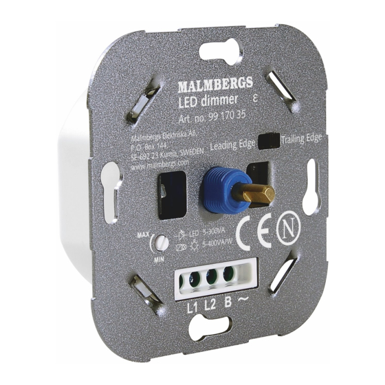
99 170 35
DK
DrEJELySDæMPEr uNIvErSAL, Lrc
Læs vejledningen inden start af installation og giv
vejledningen til brugeren når installationen er færdig.
TEKNISKE DATA
Mærkespænding
Frekvens
Max. LED belastning
Maks. antal drivere / armaturer
Min. LED belastning
Lysdæmper type
12v halogen med elektro-
nisk trafo
glødelamper / 230v halogen
lamper
ANvENDELSE
• har mulighed for korrespondance.
• Kompatible med for og bagkant LED lyskilder.
• Soft start.
INSTALLATION
Læs vejledningen inden installation og gem denne
som fremtidigt reference.
• Installation skal udføres af elektriker, og nationale
DK
regler skal følges.
EN
• Installationen skal udføres uden spænding.
FI
NO
SE
LySDæMPEr MODE INDSTILLINg
Lysdæmperen har indbygget micro switch som gør det
muligt at ændre lysdæmper mode.
• Micro switch til venstre er forkant mode / dæmpning.
• Micro switch til højre er bagkant mode / dæmpning.
Forbindelses skema
Lysdæmper alene
Lysdæmper i korrespondance
OBS:
• Installation skal udføres af elektriker, og nationale regler
skal følges.
• Installationen skal udføres uden spænding.
• Forbind ikke flere lysdæmpere til samme belastning.
EN
MANuAL SWITch LEADINg/
TrAILINg EDgE DIMMEr, rcL
Read these instructions before starting the installation
and hand it over to the user when finished.
TEchNIcAL DATA
220-240v ~
Operating voltage
50hz
Frequency
Lr: 150W
Max. LED load
cr: 300W
15
Max. qty of drivers/luminaires
5W
Min. LED load
Lrc - Forkant/bagkant
Dimming type
5-400vA/W
electronic transformers
Incandescent lighting, 230v
5-400vA/W
halogen lamps
FEATurES
• Suitable for two way dimming.
• compatible with leading and trailing edge load.
• Soft-start.
INSTALLATION
Please read instructions before commencing
installation and retain for future reference.
• The installation must be carried out by a qualified
• Make sure that the electricity is switched off during
DIMMINg MODE SELEcTION
There is a micro switch on the dimmer which allows you to
change the dimming mode.
• Switch to the left means leading edge mode.
• Switch to the right means trailing edge mode.
Wiring Diagram
1 gang
1 gang, 2 Way
Please note:
• The installation must be carried out by a qualified electri-
cian, taking into account the national rules.
• Make sure that the electricity is switched off during
installation.
• you cannot connect more than one dimmer in parallel to
operate the same charge from two points.
220-240v ~
Leading edge: 150W
Trailing edge: 300W
Leading/trailing edge
12v halogen lighting with
5-400vA/W
5-400vA/W
electrician, taking into account the national rules.
installation.
50hz
15
5W
Advertisement
Table of Contents

Related Manuals for Malmbergs 99 170 35


Summary of Contents for Malmbergs 99 170 35
- Page 1 99 170 35 DrEJELySDæMPEr uNIvErSAL, Lrc MANuAL SWITch LEADINg/ TrAILINg EDgE DIMMEr, rcL Læs vejledningen inden start af installation og giv Read these instructions before starting the installation vejledningen til brugeren når installationen er færdig. and hand it over to the user when finished.
- Page 2 uNIvErSAALISääDIN, rcL uNIvErSALDIMMEr, rcL uNIvErSALDIMMEr, rcL Les disse instruksjonene før du begynner installasjo- Lue nämä ohjeet huolella ennen asennusta ja luovuta Läs dessa anvisningar innan du börjar installationen nen og overlever den til brukeren når du er ferdig. loppukäyttäjälle kun työ on valmis. och överlämna den till användaren när du är klar.
Need help?
Do you have a question about the 99 170 35 and is the answer not in the manual?
Questions and answers