Table of Contents
Advertisement
Quick Links
DATA SHEET
INDUSTRIAL CLUTCHES
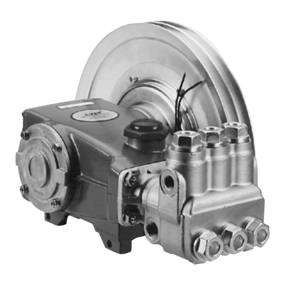
7 Frame Plunger Pumps
34628
SELECTION
Select the clutch to match the pump shaft size and belt horse-
power rating.
INSTALLATION
1. Remove the four bearing cover screws on pump and discard.
2. On 7 frame plunger pumps, line up the clutch plate countersunk holes
with the bearing cover screw holes. Secure with four countersunk
head screws (M6) and lockwashers (M6) and torque per specifications.
Do not use pump bearing cover screws.
3. On 15 frame plunger pumps, using spacer as an alignment tool, slide
large diameter end of spacer first over shaft of pump. Install clutch plate
over spacer until flush against crankcase. Ensure countersunk holes of
clutch plate line up with bearing cover screw holes. Secure with four
countersunk head screws (M6) and lockwashers (M6) and torque per
specifications. Do not use pump bearing cover screws.
4. Remove spacer from crankshaft. Reverse the position of the spacer so
that small diameter end now faces the pump.
5. Mount the coil assembly onto the clutch plate and secure with three
flanged screws and torque evenly per specifications.
6. Lubricate the pump shaft with antiseize lubricant.
7. Place clutch assembly on work surface with visable bearing facing up.
8. Position pulley on clutch assembly with concave up. On dual grooves,
place second pulley with concave down.
9. Line up the six pulley holes with six clutch assembly holes. Secure with
six socket head cap screws and torque per specifications.
10. Slide the Clutch/Pulley assembly over shaft. Be certain keyway of
pump is aligned with armature keyway and insert the key into the
pump shaft. Secure with flat washer and shaft screw (M8x25) and
torque per specifications.
7 Frame Plunger Pumps
Pump Model 56 shown (pump sold separately)
34630
FEATURES
• Special e-coating offers 3 to 6 times better corrosion resistant finish.
• Special bearings with unique grease offer more
consistent viscosity at high temperatures and better water resistance for
harsh environments.
• Special projection welded coil and plate offers extra durability in heavy
vibration applications.
• Superior strength forged rotor, hub and armature offer superior flux and
maximum torque for long life.
SPECIFICATIONS
Pump Frame
Pulley Grooves
Shaft Diameter
COMMON
SPECIFICATIONS
Pitch Diameter
Belt Type
Torque
Watts
Amps
Power Required
Weight (1 Pulley)
Weight (2 Pulley)
Dimensions
11. Connect the lead wire to the positive side of the electric circuit. Also
be certain there is an adequate grounded connection to the coil
assembly plate.
12. Engage and disengage the clutch to assure proper functioning. If full
load is required initially from the pump, allow clutch to engage 20-50
cycles before commencing normal operation for adequate burnishing.
NOTE: Follow standard belt mounting and center distance procedures to
determine drive pulley size, speed and horsepower per belt.
OPERATION
The clutch works with a flow switch, pressure switch or a manual on/off
switch installed in the system and connected to a 12VDC power supply.
When the trigger gun is released or the unit is manually turned off, a
signal is sent to the clutch to disengage and cease pump operation. When
operation resumes by opening the trigger gun or manually turning the
system on, the clutch will engage, starting the pump and resuming full
operation.
15 Frame Plunger Pumps
34563
34628
34630
7 Frame
7 Frame
1
2
24 mm
24 mm
U.S.
12.4"
B
100 ft./lbs.
50
4.2
12 VDC
18.2 lbs.
22.0 lbs.
2.45 x 12.75"
62 x 324 mm
34563
15 Frame
2
30 mm
Metric
315 mm
B
135 Nm
50
4.2
12 VDC
8.25 kg
9.97 kg
Advertisement
Table of Contents

Related Manuals for CAT Pumps 34628


Summary of Contents for CAT Pumps 34628
- Page 1 DATA SHEET INDUSTRIAL CLUTCHES 7 Frame Plunger Pumps 7 Frame Plunger Pumps 15 Frame Plunger Pumps 34628 34630 34563 FEATURES • Special e-coating offers 3 to 6 times better corrosion resistant finish. • Special bearings with unique grease offer more consistent viscosity at high temperatures and better water resistance for harsh environments.
- Page 2 All High Pressure Systems require a primary pressure regulating device (i.e. regulator, unloader) and a secondary pressure relief device (i.e. pop-off valve, relief valve). Failure to install such relief devices could result in personal injury or damage to pump or property. Cat Pumps does not assume any liability or responsibility for the operation of a customer’s high pressure system.
Need help?
Do you have a question about the 34628 and is the answer not in the manual?
Questions and answers