
Subscribe to Our Youtube Channel
Related Manuals for FabiaTech FX5328


Summary of Contents for FabiaTech FX5328
- Page 1 FabiaTech Corporation IPC Solution Website: http://www.fabiatech.com Email: support@fabiatech.com Small Cube System Fanless Series FX5328 User’s Manual JUNE 2017 Version: 1.0 Part Number: FX5328...
- Page 2 FabiaTech shall not be reliable for technical or editorial errors or omissions, which may occur in this document. FabiaTech shall not be reliable for any indirect, special, incidental or consequential damages resulting from the furnishing, performance, or use of this document.
-
Page 3: Table Of Contents
Table of Contents FX5328 User’s Manual ......................i Chapter 1 Introducing the FX5328 System ................1 Overview..........................1 Series Comparison Table .......................2 Layout............................3 Specifications..........................4 Packing List ..........................5 Chapter 2 Hardware Installation ....................7 Before Installation ........................7 Removing Covers –Installing Hardware............8 I/O Peripheral Connectors ................12 ... - Page 4 Boot ............................46 CSM Parameters ....................48 Security...........................50 Save & Exit ..........................53 Chapter 4 Software Installation ....................55 Install AMD Catalyst ™ Drivers....................55 WIN XP/7 32/64 Driver....................55 Audio Driver...........................56 WIN XP/7 X86/X64 Driver ...................56 LAN Driver (RTL 8111F) ......................56 WIN XP/7 Driver X86/X64 Driver ................56 BIOS Flash Utility........................57 Watchdog Timer........................58 Watchdog Timer Setting ..................59...
-
Page 6: Chapter 1 Introducing The Fx5328 System
FabiaTech Corporation Chapter 1 Introducing the FX5328 System Overview The FX5328 is an embedded system with AMD® G-Serial T40E Processor low-power CPU module inside. This user’s manual provides information on the physical features, installation, and BIOS setup of the FX5328. -
Page 7: Series Comparison Table
FabiaTech Corporation Series Comparison Table Model FX5328 System Processor AMD® G-Serial T40E 1.0 GHZ Memory DDR3L-1066 204 Pin-DIMM*1 4GB (8GB Max.) Storage One CFAST Socket One SD Socket One 2.5’ SATA HDD Connector Display VGA+DP Multi I/O One RS232/RS422/RS485 One RS232/RS422/RS485 or CAN (SJA1000) USB 2.0... -
Page 8: Layout
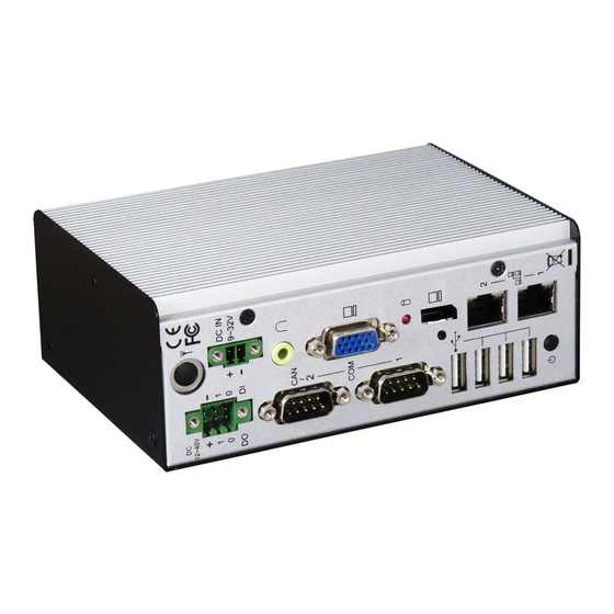
FabiaTech Corporation Layout ANTENNA 12~40V DIGITAL I/O DC IN 9~32V DC IN EAR-PHONE COM2/CAN COM1 DISPLAY LAN1 LAN2 POWER BUTTON... -
Page 9: Specifications
FabiaTech Corporation Specifications Processor Board – AMD® G-Serial T40E 1.0 GHZ (512KB L2 Cache For Per Core) Dual Core Low Power Processor with 4GB DDR3L/1066 RAM I/O Outlets – Two 10/100/1000 base-TX Ethernet LAN port with RJ45 Supports Display port and one VGA connector with DB15 One Audio connector for Earphone-Out 4 USB ports (2.0) with type A connector... -
Page 10: Packing List
Verify the accessories in the package according to the packing list and see if there is anything missing or incorrect package is included. • If the cable(s) you use to install the FX5328 is not supplied from us, please make sure the specification of the cable(s) is compatible with the FX5328 system. - Page 11 FabiaTech Corporation...
-
Page 12: Chapter 2 Hardware Installation
FabiaTech Corporation Chapter 2 Hardware Installation This chapter introduces the system connectors & jumper settings, and guides you to apply them for field application. Before Installation Before you install the system, make sure you follow the following descriptions. 1. Before removing the cover, shut down the operation System and disconnect power switch to off and unplug DC-In cable. -
Page 13: Removing Covers -Installing Hardware
If you are installing hardware option, you can remove the front and back cover. The following figure will guide you how to install CFAST modules, SD Card, 2.5" HDD inside and PCIe Mini card the FX5328 and how to install the FX5328 fixers. (Please see the spots circled.) a. - Page 14 FabiaTech Corporation c. Installing Memory: So-DIMM Socket for DDR3L RAM Modules You may extend additional memory to FX5328, See as following figure and rear pictures. The So-DIMM socket supports 2GB to 8GB of DDR3L RAM modules. d. Installing PCIe Mini Card Module –Daughter Board You may extend additional PCIe mini card module and SIM card to FX5328.
- Page 15 Installing Half Size Mini PCIe module kit (Optional) e. Installing the DIN-Rail fixers or universal fixers on FX5328 Please refer to the down side figure for installing the FX5328 with universal fixers. e1. FX5328 Din-Rail e2. FX5311K1 – Panel Back Mounting (VESA Mount 75*75)
- Page 16 FabiaTech Corporation e3. FX5407K3 – Panel Mounting Kit (VESA Mount 50*50/75*75/100*100) M3*P0.5 M4*P0.7...
-
Page 17: I/O Peripheral Connectors
FabiaTech Corporation I/O Peripheral Connectors View from the back side, if you are connecting the monitor, LAN, COM, CAN, Audio, Digital I/O and USB to the FX5328. See following figure and a side pictures. ANTENNA 12~40V DIGITAL I/O DC IN... - Page 18 FabiaTech Corporation 3. Connecting the COM ports The COM1 and COM2 (DB9) are designed for multiple proposes, It’s can select RS- 232/422/485/CAN (The CAN port Only for COM2) by BIOS jumper setting. The following tables show the signal connections of these connectors.
- Page 19 USBD- (V2.0) USBD+(V2.0) USBG (Front View) Digital I/O Connector The FX5328 provides 2-in and 2-out isolated digital I/O, output port is an open collector, you will need connections external voltage of Digital (+) and digital (-) connector. D I/O DI/O...
- Page 20 FabiaTech Corporation Connecting the Audio EAR-Phone EAR-Phone...
-
Page 21: Connecting The Dc Power And Power Button
FabiaTech Corporation Connecting the DC Power and Power Button Power is supplied through an external power DC In. See following figure and a side pictures. 1. DC Power Connector: Use external 2-pin apartable terminal block. DC IN 9V~32V Terminal Block... -
Page 22: Switch And Jumper Setting
FabiaTech Corporation Switch and Jumper Setting The serial port is designed for multiple proposes, you can use SW2 and SW1 selects RS-232, RS-422, RS485; SW4 selects RS485 terminator resistor, JP3 and JP6 can to select power source (+5V or 12V) with RI# pin of DB9-Pin9. The JP5 select CAN (only COM2);... - Page 23 FabiaTech Corporation a. SW4: RS-485 Terminator Setting SW4-2 SW4-1 (COM2) (COM1) RS-485 Terminator Disabled RS-485 Factory Preset Terminator Enabled b. COM1 & COM2 Power Source Jumper Select The COM1 and COM2 ports provide power source + 5V or +12V will driver the “RI”...
- Page 24 FabiaTech Corporation PCIe mini-Card auxiliary power source selection When installing the PCIe Mini Card module, if not correct working (See a PCIe module card specification pin-24 3.3VAUX.), you can to select 3VSB/3.3V voltage. Power source Form VCC3 Power source Form 3VSB...
- Page 25 FabiaTech Corporation...
-
Page 26: Chapter 3 Bios Setup
FabiaTech Corporation Chapter 3 BIOS Setup This chapter describes the BIOS setup. Overview BIOS are a program located on a Flash memory chip on a circuit board. It is used to initialize and set up the I/O peripherals and interface cards of the system, which includes time, date, hard disk drive, the ISA bus and connected devices such as the video display, diskette drive, and the keyboard. -
Page 27: Bios Functions
FabiaTech Corporation BIOS Functions On the menu, you can perform the following functions 1. Main 2. Advanced ACPI Settings CPU Configuration IDE Configuration USB Configuration SMART Settings F81216 Super IO Configuration H/W Monitor WAKE Configuration 3. Chipset North Bridge South Bridge 4. -
Page 28: Keyboard Convention
FabiaTech Corporation Keyboard Convention On the BIOS, the following keys can be used to operate and manage the menu: Function [↑][↓] The Up and Down keys allow you to select item. [←][→] The Left and Right keys allow you to select screen. -
Page 29: Main Setup
FabiaTech Corporation Main Setup This section describes BIOS version information and basic system hardware configuration. If the CPU board is already installed in a working system, you will not need to select this option anymore. System Date & Time Setup Highlight the <Date>... -
Page 30: Advanced Setup
FabiaTech Corporation Advanced Setup Select the Advanced tab from the setup screen to enter the Advanced BIOS Setup screen. You can select any of the items in the left frame of the screen, such as USB Configuration, to go to the sub menu for that item. You can display an Advanced BIOS Setup option by highlighting it using the <Arrow>... -
Page 31: Acpi Settings
FabiaTech Corporation ACPI settings This filed specifies allow you set this value to utilize the ACPI (Advanced Configuration and Power Interface) specification. Enabled ACPI Auto Configuration This item allows users to enable or disable BIOS ACPI Auto Configuration. Available Options: Disabled, Enabled... - Page 32 FabiaTech Corporation ACPI Sleep State This item allows users to select the highest ACPI sleep state the system will enter when the SUSPEND button is pressed. Available Options: Suspend Disabled and S1 Only (CPU Stop Clock). Default setting: Suspend Disabled Lock Legacy Resources This item allows users to enable or disable Lock of Legacy Resources.
-
Page 33: Cpu Configuration
FabiaTech Corporation CPU Configuration The Item Display CPU Information, like CPU speed and L1/L2 cache and support function, you can use this screen to select options for the CPU information. Use the up and down <Arrow> keys to select an item. Use the <Plus> and <Minus> keys to change the value of the selected option. - Page 34 FabiaTech Corporation PPC Adjustment This field provides to adjust _PPC objects. Available Options: PSTATE0, and PSTATE2 Default setting: PSTATE0 NX Mode This field allows the users to enable or disable the No-executed page Protection functions. Available Options: Disabled, and Enabled...
-
Page 35: Ide Configuration
FabiaTech Corporation IDE Configuration You can use this screen to select options for the SB SATA Configuration. - Page 36 FabiaTech Corporation SB SATA Configuration OnChip SATA Channel This item allows users to enable or disable SATA Controller. Available Options: Disabled, and Enabled Default setting: Enabled OnChip SATA Type Select a configuration for SATA controller. Install Windows XP in AHCI mode need to use the F6 Method pre-installed AHCI driver, if you select Legacy IDE mode, you do not need to pre-install.
-
Page 37: Usb Configuration
FabiaTech Corporation USB Configuration You can use this screen to select options for the USB Configuration. Legacy USB Support Legacy USB Support refers to the USB mouse and USB keyboard support. Normally if this option is not enabled; any attached USB mouse or USB keyboard will not become available until a USB compatible operating system is fully booted with all USB drivers loaded. - Page 38 FabiaTech Corporation USB Mass Storage Driver Support Mass storage device emulation type. If the emulation FDD, recommended formatted as FAT32 format. Available Options: Disabled, and Enabled Default setting: Enabled USB transfer time-out The time-out value for control, bulk, and interrupt transfers.
- Page 39 FabiaTech Corporation Device power-up delay > Select “Manual“ Device Power-Up delay in second Delay range is 1...40 seconds, in one second increments Available Options: 1, 5, 10, 20, 30, and 40 Sec Default setting: 5 Sec Generic Storage Device 1.01 Mass storage device emulation type.
-
Page 40: F81216 Super Io Configuration
FabiaTech Corporation F81216 Super IO Configuration This section describes the function of Super I/O settings. Serial Port 0/ Port 1 Configuration These fields select the I/O port address for Serial port 0 and port 1. - Page 41 FabiaTech Corporation Serial Port 0/1 This item allows users to select the enable or disable Serial port. Available Options: Enabled, and Disabled. Default setting: Enabled Device Settings Serial Port0: IO=3F8; IRQ=IRQ4; Serial Port1: IO=2F8; IRQ=IRQ3 Transfer Mode Setting This item allows users can select RS-232, RS-422 and RS-485 of select COM1/COM2.
-
Page 42: Hardware Health Configuration
FabiaTech Corporation Hardware Health Configuration On the Hardware Monitor Setup screen, you can monitor the system temperature1, System voltage, and VBAT voltage…... -
Page 43: Wake Configuration
FabiaTech Corporation Wake Configuration Onboard PCIE LAN PXE ROM This field specifies the PXE boot ROM of the onboard LAN chip. Available Options: Disabled, and Enabled Default setting: Disabled Wake ON Lan This item is can select Enabled to integrated LAN to wake up the system. -
Page 44: Realtek Pcie Gbe Family Controller (Mac)
FabiaTech Corporation Realtek PCIe GBE Family Controller (MAC) On the LAN Information screen, you can see the LAN Chipset information, when setting the Launch PXE OpROM Policy to UEFI Only of CSM Boot. -
Page 45: Chipset
FabiaTech Corporation Chipset This section describes the configuration of the board’s chipset features. • North Bridge • South Bridge... -
Page 46: North Bridge
FabiaTech Corporation North Bridge You can use this screen to select options for the Host Bridge Configuration. Use the up and down <Arrow> keys to select an item. Use the <Plus> and <Minus> keys to change the value of the selected option. - Page 47 FabiaTech Corporation GFX Configuration On the Socket 0 Information screen, you can see the system memory information. Port 4/5/6 Control (Mini-Card/Onboard LAN1/Onboard LAN2) The onboard LAN corresponding PCI Express port 4/5/6, the item allows users to enable or disable on board PCIe Mini Card/LAN1/LAN2.
-
Page 48: South Bridge
FabiaTech Corporation South Bridge You can use this screen to select options for the South Bridge Configuration. South Bridge is a chipset on the motherboard that controls the USB, and audio function. Restore On AC Power Lose This field specifies the option controls how the PC will behave once power is restored following a power outage (or other unexpected or ungraceful shutdown). - Page 49 FabiaTech Corporation USB Configuration OHCI HC (Bus 0 Dev 18 FN 0) The USB OHCI HOST Control each of the USB ports (0~5). Enable: Enable USB 0/1, 2/3, 4/5 port; Disable: Use USB port 0/1, 2/3, 4/5 settings Available Options: Disabled, and Enabled...
- Page 50 FabiaTech Corporation Azalia HD Audio Audio Controller This item allows users to enable or disable Azalia Controller. Available Options: Auto, Disabled, and Enabled Default setting: Enabled...
-
Page 51: Boot
FabiaTech Corporation Boot Select the Boot tab from the setup screen to enter the Boot BIOS Setup screen. You can select any of the items in the left frame of the screen, such as Boot Device Priority, to go to the sub menu for that item. You can display a Boot BIOS Setup option by highlighting it using the <Arrow>... - Page 52 FabiaTech Corporation Bootup NumLock State This field is used to activate the Num Lock function upon system boot. If the setting is on, after a boot, the Num Lock light is lit, and user can use the number key. Available Options: On, and Off...
-
Page 53: Csm Parameters
FabiaTech Corporation CSM Parameters The CSM (Compatibility Support Module) is Option ROM Execution, boot options filter, etc. Launch CSM This item allows users to enable or disable CSM. Available Options: Disabled, and Enabled Default setting: Enabled Boot Option Filter This option controls Legacy/UEFI ROMs priority. - Page 54 FabiaTech Corporation Launch Storage OpROM Policy This option Controls the execution of UEFI and Legacy Storage OpROM. Available Options: Do not Launch, Legacy only, UEFI only, Leach First and UEFI First. Default setting: Do not Launch Launch Video OpROM Policy This option Controls the execution of UEFI and Legacy Video OpROM.
-
Page 55: Security
FabiaTech Corporation Security Security Setup provides both Administrator and User password. If you use both passwords, the Administrator password must be set first. The system can be configured so that all users must enter a password every time the system boots or when Setup is executed, using either the Administrator password or User password. - Page 56 FabiaTech Corporation Clear Old Password Select Administrator/user password item, press <Enter> and type current password, at the next dialog press <Enter> to Clear Old Password.
- Page 57 FabiaTech Corporation HDD Security Configuration Customizable HDD Password Secure Boot settings, when HDD/SSD device is support.
-
Page 58: Save & Exit
FabiaTech Corporation Save & Exit Save Changes and Exit When you have completed the system configuration changes, select this option to save the changes and Exit, so the new system configuration parameters can take effect. Discard Changes and Exit Select this option to quit without making any modifications to the system configuration. - Page 59 FabiaTech Corporation Discard Changes and Reset Select this option to reboot the system without saving the changes done in the setup configuration. Save Changes When you have completed the system configuration changes, select this option to save your system configuration and continue. For some of the options it required to reset the system to take effect.
-
Page 60: Chapter 4 Software Installation
FabiaTech Corporation Chapter 4 Software Installation The enclosed CD diskette includes FX5328 VGA, System, Audio, and LAN driver. To install and configure you FX5328 system, you need to perform the following steps. Install AMD Catalyst ™ Drivers WIN XP/7 32/64 Driver To install the AMD T40E driver, insert the DVD ROM into the USB DVD ROM device, and enter DRIVER>VGA>AMD_T40E>WINXP, or >WIN7. -
Page 61: Audio Driver
FabiaTech Corporation Step 9: The AMD - Catalyst Install Manager will analyze the system, and install the required files. Step10: The AMD - Catalyst Install Manager will confirm when the installation is complete. Click Finish. Step11: When prompted, Click Yes to restart the system and complete the installation process. -
Page 62: Bios Flash Utility
FabiaTech Corporation BIOS Flash Utility In the <UTILITY> directory, there is the AFU301.EXE file. Step 1: Use the AFU301.EXE xxxxxVxx.rom program to update the BIOS setting. Step 2: And then refer to the chapter “BIOS Setup”, as the steps to modify BIOS. -
Page 63: Watchdog Timer
This section describes how to use the Watchdog Timer, including disabled, enabled, and trigger functions. The FX5328 is equipped with a programmable time-out period watchdog timer. You can use your own program to Enabled the watchdog timer. Once you have enabled the watchdog timer, the program should trigger the I/O every time before the timer times out. -
Page 64: Watchdog Timer Setting
FabiaTech Corporation Watchdog Timer Setting The watchdog timer is a circuit that may be used from your program software to detect system crashes or hang-ups. The watchdog timer is automatically disabled after reset. Once you have enabled the watchdog timer, your program must trigger the watchdog timer every time before it times out. -
Page 65: Watchdog Timer Enabled
FabiaTech Corporation Watchdog Timer Enabled To enable the watchdog timer, you have to output a byte of timer factor to the watchdog register whose address is 2eh and data port is 2fH. The following is a demo program, which demonstrates how to enable the watchdog timer and set the time-out period at 20 seconds. -
Page 66: Watchdog Timer Trigger
FabiaTech Corporation Watchdog Timer Trigger After you enable the watchdog timer, your program must write the same factor as enabling to the watchdog register at least once every time-out period to its previous setting. You can change the time-out period by writing another timer factor to the watchdog register at any time, and you must trigger the watchdog before the new time-out period in next trigger. -
Page 67: Digital I/O (Gpio) Programming
FabiaTech Corporation Digital I/O (GPIO) programming The following is a WATCOM C/C++ program, which demonstrates how to read and write the data of GPIO. The Digital I/O need use memory operands read and write. ;---------------------------------------------------------------------------------------------------------------- ; Configuration the Digital I/O use memory address. -
Page 68: Canbus
Isolation Defined Memory Mapping And Interrupt The CANBUS occupies 2 bytes of FX5328 memory space. You can set the base address and access to the internal resources of the SJA1000 CAN controller chip. The SJA1000 chip access is multiplexed in such a way that the host must first write to 300h the internal address of the CAN chip and after that perform a write to address 301h with the actual data to be written into the desired memory location. -
Page 69: Example Programming
FabiaTech Corporation Example Programming Write 300H to the CAN controller Control byte located in the on-chip address 0.The Example is listed below: Outportb (0x300,0x00) ; Write CAN Address 0 (Control Register ) Outportb (0x301,0x78) ; Write Data of CAN Address 0 (Control Register ) -
Page 70: Chapter 5 Technical Reference
FabiaTech Corporation Chapter 5 Technical Reference This section outlines the errors that may occur when you operate the system, and also gives you the suggestions on solving the problems. Topic include: Technical Reference Dimension Technical Reference Physical and Environmental Temperature: Operating -10°C ~+ 55℃ (14~131℉) Relative humidity 5 % to 95 % non-condensing Surface Temperature of Chassis:... -
Page 71: Serial Ports
FabiaTech Corporation Serial Ports The ACEs (Asynchronous Communication Elements ACE1 to ACE2) are used to convert parallel data to a serial format on the transmit side and convert serial data to parallel on the receiver side. The serial format, in order of transmission and reception, is a start bit, followed by five to eight data bits, a parity bit (if programmed) and one, one and half (five-bit format only) or two stop bits. - Page 72 FabiaTech Corporation Bit 1: Enable Transmitter Holding Empty Interrupt (ETBEI) Bit 2: Enable Receiver Line Status Interrupt (ELSI) Bit 3: Enable MODEM Status Interrupt (EDSSI) Bit 4: Must be 0 Bit 5: Must be 0 Bit 6: Must be 0...
- Page 73 FabiaTech Corporation Bit 5: Stick Parity Bit 6: Set Break Bit 7: Divisor Latch Access Bit (DLAB) MODEM Control Register (MCR) Bit 0: Data Terminal Ready (DTR) Bit 1: Request to Send (RTS) Bit 2: Out 1 (OUT 1) Bit 3: Out 2 (OUT 2)
- Page 74 FabiaTech Corporation Bit 4: Clear to Send (CTS) Bit 5: Data Set Ready (DSR) Bit 6: Ring Indicator (RI) Bit 7: Received Line Signal Detect (RSLD) Divisor Latch (LS, MS) Bit 0: Bit 0 Bit 8 Bit 1: Bit 1...
-
Page 75: Appendix
FabiaTech Corporation Appendix Dimension a. FX5328 Rail Adapter On 35mm Din-Rails (EN 50022:1977) - Page 76 FabiaTech Corporation b. 5311K1 37.5(REF) 61(REF) Rail Adapter 72.5(REF) On 35mm Din-Rails for h=7.5 52(REF) (EN 50022:1977) 17.5(REF) for h=15 25(REF)
- Page 77 FabiaTech Corporation c. FX5407K3 11.5(REF) 22.5(REF) 12.5 12.5 O4.5...
Need help?
Do you have a question about the FX5328 and is the answer not in the manual?
Questions and answers