Table of Contents
Advertisement
Quick Links
Advertisement
Table of Contents

Subscribe to Our Youtube Channel
Related Manuals for Simpson 897


Summary of Contents for Simpson 897
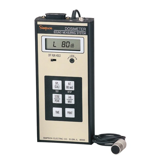
- Page 1 Model 897 Dosimeter Sound Measuring System OPERATOR’S MANUAL DOSIMETER SOUND MEASURING SYSTEM LO BATT % DOSE SPL MAX INT 60s OFF RUN HOLD LOCK "CAL" (60 sec) TEST SETUP DOSE PEAK TIME PRINT SIMPSON ELECTRIC CO. ELGIN , IL 60120...
- Page 2 SIMPSON ELECTRIC COMPANY neither assumes nor autho- rizes any other persons to assume for it any other liability in connection with the sales of its products.
- Page 3 NOTES...
-
Page 4: Table Of Contents
Contents 1. INTRODUCTION ................7 General Description ................7 Items Furnished With Instrument ............7 Technical Data ..................8 2. PREPARATION FOR USE ............... 11 Unpacking And Inspection ............... 11 Preparation For Use ................. 11 Warranty ...................12 Shipping ...................12 3. APPLICATION ................. 12 Decibel Scale ...................12 Sound Level Meter ................12 Measurement And Exposure Standards ..........13... - Page 5 NOTES...
- Page 6 NOTES...
-
Page 7: Introduction
Measuring continuous, intermittent and impulsive noise in the standard range from 80 dBA to 130 dBA, the 897 also offers a 50 to 100 dB range where lower sound level analysis is desired. When used as a personal noise dosimeter, the 897 may be worn in a shirt pocket or on a belt. -
Page 8: Technical Data
Technical Data The 897 conforms to ANSI S1.4-1983, ANSI S1.25-1978, and IEC651 (1979) standards for type S2A sound level meters and noise dosimeters. Table 1-2 lists the technical specifications for the 897 Noise Dosimeter/Sound Level Meter. Table 1-2. Instrument Specifications... - Page 9 17. Calibration: Instantaneous with 100 Hz, 94 dB or 114 dB SPL calibrator and adjustment on the top of the 897. However, an annual factory recalibration is recommended. 18. 140 dB Peaks: Front panel selectable display indicates number of 140 dB peaks that have been de- tected.
- Page 10 The clock contin- ues running even with power “OFF”. 21. Power Requirements: The 897 is designed to be used with the Simpson battery charger, part number 6- 115095, which is adequately insulated to permit use of the 897 while being charged.
-
Page 11: Preparation For Use
Table 1-1 are included in shipment. Save the shipping carton for possible future shipping of the Instrument. NOTE: The 897 is powered by a self-contained rechargeable nickel cadmium battery pack. Charge Instrument for 16 hours before use. Preparation For Use... -
Page 12: Warranty
NOTE: All OSHA type sound level meters must be A-weighted. B and C weightings are not required for compliance measurements. The sound level meter function of the 897 meets the requirements of the Ameri- can National Standards Institute (ANSI) Standard Specification S1.4 1983 for... -
Page 13: Measurement And Exposure Standards
B AND C –5 –10 –15 –20 FREQUENCY RESPONSES FOR SLM WEIGHTING –25 CHARACTERISTICS –30 –35 –40 –45 –50 1000 2000 5000 10,000 20,000 FREQUENCY (Hz) Figure 3-1. A, B & C Weighted Electrical Responses Measurement And Exposure Standards Sound level meter measurement standards are defined in American National Standards Institute (ANSI) Specification S1.4-1983. - Page 14 Table 3-2. Permissable Noise Exposure Limits for Continuous Noise Varying Level Noise When daily noise exposure is composed of two or more periods of noise expo- sure at different levels, consider their combined effect rather than the individual effect of each. The total dose is computed by the expression: D + C1 + C2 + —...
-
Page 15: Impact Noise
To accurately determine a dosage level using a sound level meter is a tedious procedure, as the total length of exposure at each dB level must be weighted and summed (accumulated). The dosimeter function of the 897 automatically and continuously performs these mathematical manipulations while it is operating and provides the dosage readout directly in percent of allowable exposure. -
Page 16: Sound Fields
Sound Fields 3.6.1 Free Field This field contains no reflecting objects. Ideally it is a point sound source located in free space; however, it can be considered to exist whenever the sound level being measured is caused mainly by the sound waves coming directly from the sound source. -
Page 17: Windscreen
Windscreen NOTE: When the 897 is exposed to a dusty or windy environment, the windscreen should be used to protect the microphone diaphragm from damage, and to as- sure a correct reading. The windscreen will reduce the effects of wind noise by approximately 20 dB without seriously affecting the frequency response of the microphone. - Page 18 are suspended and printouts will indicate “HOLD” during the time SPL is selected. “HOLD”: In “HOLD” mode all data is retained without any modification except that the elapsed time clock is kept running. The display will alternately flash between “HOLD” and the presently selected function. Control Switch “LOCK”: A spline head screw is used to “lock”...
-
Page 19: Top Panel Operating Features
Figure 4-2. Top Panel Battery Charging The 897 is designed to be used with the Simpson Battery Charger(part no. 6- 115095) which is insulated well enough to permit use of the 897 while being charged. This charger has a rated input of 108V AC to 264V AC at 50/60 Hz. Use of any other charger may be hazardous to the operator or the 897. -
Page 20: Preliminary Checks
“HOLD” position, however, this time will vary according to use. Preliminary Checks Set the “OFF-RUN-HOLD” switch to the “RUN” position. When the unit is first turned on, a display segment test is performed. Next, the 897 will display in sequence given: Lc nn... -
Page 21: Setting The Dosimeter Parameters
number 1, 2 or 3, and should then freeze on this display. If this occurs, the Instrument must be returned for repair. If these tests pass, the Instrument will proceed to a “rotating digits” test. This will cycle the display through all digits and all special annunciators. This test will continue until either the “TIME”... - Page 22 NOTE: In order to determine how much the Leq exceeds the OSHA upper limit of 115 dB, set the Leq to 130 dB. Example: Serial Output, Option 1 or 2 (Prn): Option 1 formats the data in spread- sheet format for a computer; option 2 outputs the data formatted for a serial printer.
-
Page 23: Security Controls
Clock, are saved in nonvolatile memory; the settings are retained even if the battery becomes fully discharged. Security Controls The 897 has been designed with two special security provisions to prevent unau- thorized personnel from tampering with the control settings. A function lockout feature prevents selected functions from being changed. This is accomplished by selecting the desired function, and while pressing this button, moving the “OFF-RUN-HOLD”... -
Page 24: Data Output Formats
Following are sample printouts of the same data recorded by the 897 in each of the output formats. To obtain a printout in either one of the formats: first set the dosimeter to “HOLD”, then press the “PRINT” button to print the data. - Page 25 * 100.0 indicates an overrange reading on the 50 to 100 dB range. * 130.0 indicates an overrange reading on the 80 to 130 dB range. 4.12 Spreadsheet Output Format “Prn 1” SIMPSON 897 Dosimeter Sound Analysis Report Type S2A CRITERION = 90 dB THRESHOLD...
-
Page 26: Spreadsheet Output Format "Prn 1
A sample of the Spreadsheet output format is illustrated in Figure 4-5. It is very similar to the summary report, except it does not include a histograph and the minute-by-minute data is not in real-time but in elapsed time. The Spread-Sheet output is once for each minute of data saved by the data logger;... -
Page 27: Calibration
Never place the operating calibrator tightly against the ear. The high sound level could be harmful, especially to someone with a hearing deficiency. Set the “OFF-RUN-HOLD” slide switch in the 897 to the “RUN” position. Wait until the Display Test sequence is completed, then depress the SPL (CAL) switch. - Page 28 DOSE PEAK TIME PRINT SIMPSON ELECTRIC CO. ELGIN , IL 60120 Figure 4-5. Calibration Hookup (Optional) The time and date of this calibration may be recorded in the Instrument’s memory by pressing and holding the “SPL (CAL)” switch until the display flashes “CAL.” The Instrument will retain the two most recent such occurrences, which may be observed only via the DATA OUTPUT.
-
Page 29: Dosimeter Application
4.14 Dosimeter Application Data may be transferred from the Simpson 897 Dosimeter, via the units RS232 serial port, into an IBM compatible computer using the HyperTerminal program. Unfortunately, HyperTerminal is no longer available on Windows 7. Refer to Simpson’s website, www.simpsonelectric.com Technical Support/ Downloading data from the Model 897 into HyperTerminal 1. -
Page 30: Error Message
NOTES... - Page 31 NOTES...
- Page 32 SIMPSON ELECTRIC COMPANY 520 Simpson Avenue, Lac du Flambeau, WI 54538-0099 (715) 588-3311 FAX (715) 588-3326 Printed in U.S.A. Part No. 06-115891 Edition 8, 02/12 www.simpsonelectric.com...
Need help?
Do you have a question about the 897 and is the answer not in the manual?
Questions and answers