Advertisement
Quick Links
KEYSTONE
www.valves.emerson.com
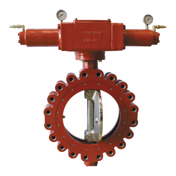
Keystone Marine High Performance Butterfly Valves
Series V30 / V32 Installation & Operation Manual
Series V30/V32 installation, operation, maintenance and
troubleshooting
1. General
Suggested installation orientation is with valve shaft horizontal or inclined from vertical. Unless
otherwise recommended by Emerson, mount the valve in the preferred direction with the directional
arrow pointing to the lower pressure side so that the front face of the disc will be upstream when
the valve is in the closed position. Thermal insulation of the body is mandatory for operating
temperatures above 200°C [392°F]. The Keystone marine high performance butterfly valve offers
the following body styles: Series V30 for wafer style and Series V32 for lug style.
2. Inspection
2.1
Carefully remove the valve from the shipping package (box or pallet) to avoid any damage
to the valve and, in the case of automated valves, to the electric or pneumatic/hydraulic
actuator or instrumentation.
2.2
Prior to installation, clean the inside of the valve. Insure that there are no solid objects such
as pieces of wood, plastic or packing materials within the valve or on the valve seat.
2.3
Inspect the seat and disc edge to insure that they were not damaged in handling. This is
especially important in the case of valves with 'fail- open' actuators.
2.4
Confirm that the materials of construction listed on the valve body are appropriate for the
service intended and are as specified.
2.5
Locate the directional arrow on the valve name plate that defines the preferred mounting
orientation in respect to the pressure. In most cases, the valve is properly installed when
the actual fluid flow or high pressure is acting on the front face of the disc when the valve is
closed.
2.6
Ensure that the packing seal cover screws are tight.
Caution
The valve should be installed in the closed position to insure that the seat and disc are not
damaged during installation. Particular care should be taken with valves equipped with 'fail
open' actuators. Failure to insure proper handling may result in damage to the valve. If the
pipe is lined, confirm that the disc rotation does not contact the lining during the opening
stroke. Failure to confirm that the disc rotation does not contact the lining may result in
damage to the valve.
Important
Whenever possible, install the valve with the shaft in the horizontal position and, if possible,
with the cast-in disc stop located top-side of the pipe. If the shaft cannot be positioned
horizontally, position the shaft so that it is not on the vertical centerline in a horizontal pipe
run. This will minimize any depositing of solid particles present in the fluid into the lower
bearing.
Keystone is either a registered trademark of Emerson International Service AG or its affiliates in the United States
and/or other countries. All other brand names, product names, or trademarks belong to their respective holders.
Emerson reserves the right to change the contents without notice
Copyright © 2017 Emerson. All rights reserved.
KVKEW-0149-EN-1309
Advertisement

Related Manuals for Emerson KEYSTONE V30 Series


Summary of Contents for Emerson KEYSTONE V30 Series
- Page 1 This will minimize any depositing of solid particles present in the fluid into the lower bearing. Keystone is either a registered trademark of Emerson International Service AG or its affiliates in the United States and/or other countries. All other brand names, product names, or trademarks belong to their respective holders.
- Page 2 2. Remove the actuator and relevant connecting key. Note the actuator position relative to the valve. Emerson reserves the right to change the contents without notice page 2 Copyright © 2017 Emerson. All rights reserved.
- Page 3 Smaller discs may be removed by hand DN 50 to DN 200 (NPS 2 to NPS 8). Remove larger discs with proper hoisting equipment. Failure to do so may result in personal injury or damage to equipment. Emerson reserves the right to change the contents without notice page 3 Copyright © 2017 Emerson. All rights reserved.
- Page 4 7.9.5 Check to see that the shaft-to-packing seal contact area is free of scratches. Note: If scratched or galled, these surfaces should be polished or replaced. Emerson reserves the right to change the contents without notice page 4 Copyright © 2017 Emerson. All rights reserved.
-
Page 5: Item Description
Packing seal cover Packing seal Bearing Spacer Disc taper pin Hex socket screw Hex socket screw O-ring (packing seal) See detail Detail Emerson reserves the right to change the contents without notice page 5 Copyright © 2017 Emerson. All rights reserved. - Page 6 Disc taper pin Hex socket screw Hex bolt & washer Hex socket screw O-ring (packing seal) O-ring (bottom cover) See detail Detail Emerson reserves the right to change the contents without notice page 6 Copyright © 2017 Emerson. All rights reserved.
- Page 7 Note: The two tapped holes allow the use of eye bolts so the seat retaining ring can be lifted to and from the body. Fig. 8 Emerson reserves the right to change the contents without notice page 7 Copyright © 2017 Emerson. All rights reserved.
- Page 8 2. Actuator/shaft adapter misaligned 2. Remove actuator mounting and realign 3. Air supply inadequate 3. Increase air supply pressure Emerson reserves the right to change the contents without notice page 8 Copyright © 2017 Emerson. All rights reserved.
Need help?
Do you have a question about the KEYSTONE V30 Series and is the answer not in the manual?
Questions and answers