
Related Manuals for Emerson Daniel 700 Series


Summary of Contents for Emerson Daniel 700 Series
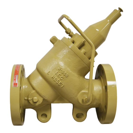
- Page 1 User manual DAN-20064957, Rev AA August 2019 ™ Daniel Series 700 - Model V707 Spring Loaded Back Pressure Valve NPS 2 through 4 / Class 150-600...
- Page 3 Email • Customer Service: DanielCST.Support@Emerson.com • Customer Support: Daniel.TechnicalSupport@Emerson.com • Field Lifecycle Services: Tech.Service@Emerson.com • Asia-Pacific: danielap.support@emerson.com • Europe: danielEMA.cst@emerson.com Return Material Authorization (RMA) A Return Material Authorization (RMA) number must be obtained prior to returning any equipment for any reason. Access and fill in the RMA form for Daniel products clicking on the link below.
- Page 4 Signal words and symbols Pay special attention to the following signal words, safety alert symbols and statements: Safety alert symbol This is a safety alert symbol. It is used to alert you to potential physical injury hazards. Obey all safety messages that follow this symbol to avoid possible injury or death.
- Page 5 • Verify that this is the correct instruction manual for your Daniel product. If this is not the correct documentation, contact Daniel at 1-713-827-6314. You may also download the correct manual from: https://www.emerson.com/en-us/automation/ daniel. • Save this instruction manual for future reference.
- Page 6 • Verify that this is the correct instruction manual for your Daniel product. If this is not the correct documentation, contact Daniel at 1-713-827-6314. You may also download the correct manual from: https://www.emerson.com/en-us/automation/ daniel. • Read and understand all instructions and operating procedures for this product.
- Page 7 Notice THE CONTENTS OF THIS PUBLICATION ARE PRESENTED FOR INFORMATIONAL PURPOSES ONLY, AND WHILE EVERY EFFORT HAS BEEN MADE TO ENSURE THEIR ACCURACY, THEY ARE NOT TO BE CONSTRUED AS WARRANTIES OR GUARANTEES, EXPRESSED OR IMPLIED, REGARDING THE PRODUCTS OR SERVICES DESCRIBED HEREIN OR THEIR USE OR APPLICABILITY. ALL SALES ARE GOVERNED BY DANIEL'S TERMS AND CONDITIONS, WHICH ARE AVAILABLE UPON REQUEST.
- Page 8 Warranty and Limitations 1. LIMITED WARRANTY: Subject to the limitations contained in Section 2 herein, Daniel Measurement & Control, Inc. (“Daniel”) warrants that the licensed firmware embodied in the Goods will execute the programming instructions provided by Daniel, and that the Goods manufactured by Daniel will be free from defects in materials or workmanship under normal use and care and Services will be performed by trained personnel using proper equipment and instrumentation for the particular Service provided.
-
Page 9: Table Of Contents
User manual Contents DAN-20064957 August 2019 Contents Part I Plan Chapter 1 Introduction.........................13 1.1 Purpose of this manual........................13 1.2 Description of the 707 Backpressure Control Valves............... 13 Chapter 2 Operating conditions and specifications...............19 2.1 Operating conditions for the 707 control valve................19 2.2 Specifications for the control valve.................... - Page 10 Contents User manual August 2019 DAN-20064957 8.2 Tools required for mechanical components..................49 8.3 Disassemble/Assemble the control valve..................49 8.4 Mechanical assembly........................51 8.5 Planned maintenance tasks......................53 Chapter 9 Corrective maintenance....................55 9.1 Control valve troubleshooting......................55 9.2 Verify the return to operational condition..................55 Chapter 10 Spare parts........................57 10.1 Recommended spare parts......................57...
-
Page 11: Part I Plan
User manual Plan DAN-20064957 August 2019 Part I Plan User manual... - Page 12 Plan User manual August 2019 DAN-20064957 707 Spring Loaded Back Pressure Valve...
-
Page 13: Chapter 1 Introduction
User manual Introduction DAN-20064957 August 2019 Introduction Purpose of this manual This manual provides guidance to owners and personnel in the installation, operation and maintenance of the Daniel Series 707 Control Valve manual, DAN-20064957. It is imperative that product owners and operation personnel read and follow the information contained in this manual to ensure that the control valve is installed correctly and is operating according to the design certifications and safety considerations. - Page 14 Introduction User manual August 2019 DAN-20064957 bottom side of the piston. The pressure at the bottom side of the piston must exceed the spring force to unseat the piston and open the valve. An adjustment mechanism provides a means to adjust the spring load in the back of the piston, which adjusts the valve opening pressure within the spring’s pressure range or set point range.
- Page 15 User manual Introduction DAN-20064957 August 2019 Open valve - No control Figure 1-2 shows the valve in the open position. The pressure at the bottom of the piston P1 is greater than the force of the spring F1 plus the check valve pressure P2. Figure 1-2: Valve in open position User manual...
- Page 16 Introduction User manual August 2019 DAN-20064957 1.2.4 Part list for the 707 control valves Figure 1-3: Part identification for an NPS 2-4 inch Control Valve Table 1-1: Part description for a 707 Control Valve Item number Description Quantity Valve body Cylinder Piston Retainer Retainer Set Screw...
- Page 17 User manual Introduction DAN-20064957 August 2019 Table 1-1: Part description for a 707 Control Valve (continued) Item number Description Quantity Piston O-ring Piston Backup Rings (High Pressure) Cylinder O-ring Cylinder Head O-ring Connector, 3/8 NPT X 3/8" Tube Stainless Steel Tubing Cylinder Head SPRING COVER Spring Cover Bolts 1/4 -20...
- Page 18 Introduction User manual August 2019 DAN-20064957 707 Spring Loaded Back Pressure Valve...
-
Page 19: Operating Conditions And Specifications
User manual Operating conditions and specifications DAN-20064957 August 2019 Operating conditions and specifications Operating conditions for the 707 control valve Table 2-1: Operating conditions for the control valve Condition type Description Fluid phase Liquid Process temperature -29 °C to 66 °C (-20 °F to 150 °F) Fluid velocity Operational recommended flow velocity up to 30 ft/sec, beyond this point will result in a high pressure drop and... - Page 20 Operating conditions and specifications User manual August 2019 DAN-20064957 Table 2-1: Operating conditions for the control valve (continued) Condition type Description Materials of construction Main valve body: Steel, ASTM-A352 Gr. LCC Main valve cylinder: • NPS 2-4: 17-4 PH Main valve piston: Stainless steel (standard) Seat ring: •...
- Page 21 User manual Operating conditions and specifications DAN-20064957 August 2019 2.1.2 Environmental conditions WARNING EQUIPMENT HAZARD Never use this equipment for any purpose other than its intended use. Failure to comply may result in death, serious personal injury and/or property damage. Table 2-2: Environmental conditions Parameter type Description...
-
Page 22: Specifications For The Control Valve
Operating conditions and specifications User manual August 2019 DAN-20064957 Specifications for the control valve 2.2.1 Interface requirements WARNING EXCEEDING REQUIREMENTS HAZARD Control valve requirements are defined to ensure safe equipment operation. Do not exceed published specifications. Failure to comply may result in death, serious injury and/or damage to the equipment. Table 2-3: Interface requirements Requirements Description... - Page 23 User manual Operating conditions and specifications DAN-20064957 August 2019 Figure 2-1: Valve orientation WARNING EQUIPMENT HAZARD Never use this equipment for any purpose other than its intended use. Failure to comply may result in death, serious personal injury and/or property damage. User manual...
- Page 24 Operating conditions and specifications User manual August 2019 DAN-20064957 2.2.3 Minimum clearances for installation, operation and maintenance Figure 2-2: Dimensions of the control valve Table 2-4: Approximate weight table for the 707 control valve Line size ANSI 150-300 ANSI 600 Inches 707 Spring Loaded Back Pressure Valve...
- Page 25 User manual Operating conditions and specifications DAN-20064957 August 2019 Table 2-5: Dimensions for the 707 Backpressure Control Valve Valve Size ANSI 150 ANSI 300 ANSI 600 ANSI 150-300 ANSI 600 (in) 10-1/4 260 10-1/2 267 11-1/2 292 12-7/8 327 14-3/8 365 13-1/8 333 14-3/4 375 16-1/4 413...
- Page 26 Operating conditions and specifications User manual August 2019 DAN-20064957 707 Spring Loaded Back Pressure Valve...
-
Page 27: Control Valve Handling
User manual Control valve handling DAN-20064957 August 2019 Control valve handling Receive the control valve WARNING EQUIPMENT HANDLING AND OPERATING HAZARD Wear personal protective equipment appropriate to the situation when working with the control valve. Adhere to all safety standards and best practices for operating the equipment. -
Page 28: Lifting Conditions
Control valve handling User manual August 2019 DAN-20064957 3.2.3 Storage conditions Store the control valve in a safe area to avoid damage. WARNING CRUSHING HAZARD During installation or removal of a control valve, always place the unit on a stable platform or surface that supports its assembled weight. -
Page 29: Lifting Requirements For Personnel
User manual Control valve handling DAN-20064957 August 2019 CAUTION FORKLIFT HAZARD Do not insert the forks of a forklift into the bore when moving the control valve. Inserting the forks may cause the meter to become unstable, resulting in serious injury or equipment damage. - Page 30 Control valve handling User manual August 2019 DAN-20064957 Figure 3-1: Correct sling attachment • Only use slings with ratings that exceed the weight to be lifted. Reference all safety standards for safety factors that must be included when calculating the load rating. CAUTION SLING HAZARD Never allow the slings to come in contact with the visual indicator, position indicator,...
-
Page 31: Configure The Control Valve
User manual Control valve handling DAN-20064957 August 2019 WARNING EQUIPMENT HANDLING AND OPERATING HAZARD Wear personal protective equipment appropriate to the situation when working with the control valve. Adhere to all safety standards and best practices for operating the equipment. Failure to comply may result in death or serious injury. - Page 32 Control valve handling User manual August 2019 DAN-20064957 Figure 3-2: Control valve flow direction WARNING EQUIPMENT HAZARD Never use this equipment for any purpose other than its intended use. Failure to comply may result in death, serious personal injury and/or property damage. 3.5.2 Piping recommendations NOTICE...
- Page 33 User manual Control valve handling DAN-20064957 August 2019 Important Ensure that piping or other attachments connected to the control valve are not under stress. Important Provide fire prevention measures and equipment per local regulations. User manual...
- Page 34 Control valve handling User manual August 2019 DAN-20064957 707 Spring Loaded Back Pressure Valve...
-
Page 35: Part Ii Install
User manual Install DAN-20064957 August 2019 Part II Install User manual... - Page 36 Install User manual August 2019 DAN-20064957 707 Spring Loaded Back Pressure Valve...
-
Page 37: Chapter 4 Installation Prerequisites
User manual Installation prerequisites DAN-20064957 August 2019 Installation prerequisites Pre-start checks Ensure that the pipeline is completely free of all foreign material before installing the valve. The design of the control valve has not been assessed for the effects of traffic, wind or earthquake loading. -
Page 38: Torque Values (Flanges)
Installation prerequisites User manual August 2019 DAN-20064957 Torque values (flanges) Table 4-1: Reference torque values for Daniel Control Valve (ft-lb) flange connections Nominal pipe size ANSI class 150 ANSI class 300 ANSI class 600 (NPS) Torque pattern sequences Table 4-2: Cross-pattern tightening sequence when using single tool Nominal pipe size ANSI class 150 ANSI class 300... -
Page 39: Chapter 5 Installation Procedure
User manual Installation procedure DAN-20064957 August 2019 Installation procedure External components assembly Install the external components (e.g., flanges) onto the pipeline. The control valve is assembled at the factory. The components do not need to be uninstalled or reinstalled unless maintenance is required. CAUTION SURFACE TEMPERATURE HAZARD The control valve body and piping may be extremely hot or cold. - Page 40 Installation procedure User manual August 2019 DAN-20064957 hydraulic bolt tensioning equipment will specify number of exposed threads outside the nut. • Do not use damaged or worn stud bolts or nuts. • Do not use nuts or stud bolts that do not fit together correctly. •...
-
Page 41: Testing The Product
User manual Testing the product DAN-20064957 August 2019 Testing the product Commission the control valve After installation, commission the control valve to ensure that the equipment is working properly. Procedure 1. Inspect all bolts used to secure the control valve in-line to ensure that proper mounting procedures have been followed and that flange connections are leak- free. - Page 42 Testing the product User manual August 2019 DAN-20064957 707 Spring Loaded Back Pressure Valve...
-
Page 43: Part Iii Operate
User manual Operate DAN-20064957 August 2019 Part III Operate User manual... - Page 44 Operate User manual August 2019 DAN-20064957 707 Spring Loaded Back Pressure Valve...
-
Page 45: Chapter 7 Operation Parameters
User manual Operation parameters DAN-20064957 August 2019 Operation parameters Control valve normal operation The Daniel 707 control valves are pressure balanced, single-seated piston operated with 45° body construction. The valves are spring actuated and use pre-loaded spring force to counter the flowing stream. Unique design features and unit-built construction ensures positive leak-proof performance. - Page 46 Operation parameters User manual August 2019 DAN-20064957 707 Spring Loaded Back Pressure Valve...
-
Page 47: Part Iv Maintain
User manual Maintain DAN-20064957 August 2019 Part IV Maintain User manual... - Page 48 Maintain User manual August 2019 DAN-20064957 707 Spring Loaded Back Pressure Valve...
-
Page 49: Chapter 8 Planned Maintenance
User manual Planned maintenance DAN-20064957 August 2019 Planned maintenance Maintenance considerations Read and understand all instructions and operating procedures before performing maintenance procedure, internal component inspection, or field requirement changes. To ensure safe and accurate performance, only informed and trained personnel should install, operate, repair and maintain this product. - Page 50 Planned maintenance User manual August 2019 DAN-20064957 After the previous steps have taken place, assemble the control valve per the instructions Mechanical assembly. 8.3.1 Cylinder disassembly Procedure 1. Remove the nuts that secure the cylinder head to the valve body. 2.
-
Page 51: Mechanical Assembly
User manual Planned maintenance DAN-20064957 August 2019 Figure 8-1: Using the piston to remove the seat ring from the 150/300 lb cylinder 8. Turn the cylinder over with the ports on top when removing the high pressure seat ring. Remove the set screw from the seat ring. Turn the seat ring counterclockwise to remove the seat ring and then remove the O-ring from the cylinder. - Page 52 Planned maintenance User manual August 2019 DAN-20064957 Table 8-2: Valve cylinder head to cylinder (socket head screws) torque specifications Class Socket head screw Torque (ft-lb) size 1/4"-20 1/4"-20 1/4"-20 1/4"-20 1/4"-20 1/4"-20 1/4"-20 1/4"-20 1/4"-20 8.4.2 Standard cylinder reassembly Reassembly of a 707 control valve Procedure 1.
-
Page 53: Planned Maintenance Tasks
User manual Planned maintenance DAN-20064957 August 2019 11. Align the holes in the cylinder head with the mating holes in the cylinder and insert the screws into the holes in the cylinder head. Tighten the screws using an Allen wrench. 12. - Page 54 Planned maintenance User manual August 2019 DAN-20064957 Table 8-3: Planned maintenance tasks (continued) Task Recommended action Corrosion monitoring Daniel recommends visually inspecting the control valve for corrosion in the internal components at least once a year. Follow internal procedures for corrosion. The valve was designed without corrosion allowance.
-
Page 55: Chapter 9 Corrective Maintenance
User manual Corrective maintenance DAN-20064957 August 2019 Corrective maintenance Control valve troubleshooting Use the table below to troubleshoot the control valve. Contact the nearest Flow Lifecycle Services center for assistance with repairs of Daniel products. It is important that servicing be performed by trained and qualified service personnel. - Page 56 Corrective maintenance User manual August 2019 DAN-20064957 3. Evaluate the system setup to ensure that all components are in the correct sequence for accurate product measurement. Some components are isolation valves, strainers, flow straighteners, turbine meters, downstream sections, etc. 707 Spring Loaded Back Pressure Valve...
-
Page 57: Chapter 10 Spare Parts
User manual Spare parts DAN-20064957 August 2019 Spare parts 10.1 Recommended spare parts Table 10-1: Recommended spare parts ® Class Viton O-Ring kit 150-300 W520155-692 W526160-692 150-300 W530155-692 W536160-692 150-300 W540155-692 W546160-692 Order spare parts Contact Flow Lifecycle Services for Daniel products and provide the following information when ordering parts: •... - Page 58 Spare parts User manual August 2019 DAN-20064957 707 Spring Loaded Back Pressure Valve...
-
Page 59: Chapter 11 Decommission
User manual Decommission DAN-20064957 August 2019 Decommission 11.1 Shut down the control valve Follow the steps below to shut down and disassemble the control valve for storage or shipment. WARNING PRESSURE HAZARD The control valve is subject to pressurized fluids. Isolate the control valve upstream and downstream. - Page 60 Decommission User manual August 2019 DAN-20064957 707 Spring Loaded Back Pressure Valve...
- Page 61 User manual DAN-20064957 August 2019 User manual...
- Page 62 Daniel Measurement and Control, Inc. ("Daniel") is an Emerson Automation Solutions business unit. The Daniel name and logo are trademarks of Daniel Industries, Inc. The Emerson logo is a trademark and service mark of Emerson Electric Co. All other trademarks are the property of their respective...
Need help?
Do you have a question about the Daniel 700 Series and is the answer not in the manual?
Questions and answers