Table of Contents
Advertisement
Instruction Manual
D101957X012
Fisherr Vee-Ballt V150 and V300
NPS 14 through 20 Rotary Control Valves
Contents
. . . . . . . . . . . . . . . . . . . . . . . . . . . . . . . . .
. . . . . . . . . . . . . . . . . . . . . . . . . . . . .
. . . . . . . . . . . . . . . . . . . . . . . . . . . . . . . . .
. . . . . . . . . . . . . . . . . . . . . . . . . . . . . . .
. . . . . . . . . . . . . . . . . . . . . . . . . . . . . . . . . . .
. . . . . . . . . . . . . . . . . . . . . . . . . . . . . . . . .
. . . . . . . . . . . . . . . . . . . . . . . . .
. . . . . . . . . . . . . . . . . . . . . . . . . . . . .
. . . . . . . . . . . . . . . . . . . . . . . . . . . . . .
. . . . . . . . . . . . . . . . . . . . . . . . . . . .
. . . . . . . . . . . . . . . . . . . . . . . . . . . . . .
. . . . . . . . . . . . . . . . . . . . . . . . . .
. . . . . . . . . . . . . . . . . . . . . . . . . . . . . . .
. . . . . . . . . . . . . . . . . . . . . . . . . . . . . . . . . . .
Introduction
Scope of Manual
This instruction manual provides installation, operation, maintenance, and parts ordering information for NPS 14, 16,
and 20 V150 and for NPS 14 and 16 V300 rotary control valves. For smaller valves (NPS 1 through 12), refer to the
Vee-Ball V150, V200 and V300 Rotary Control Valves NPS 1 through 12 instruction manual (D101554X012). For
information on ENVIRO-SEALt packing, see the ENVIRO-SEAL Packing System for Rotary Valves instruction manual
(D101643X012). Refer to separate manuals for information concerning the actuator, positioner, and mounted
accessories.
Do not install, operate, or maintain V150 and V300 valves without being fully trained and qualified in valve, actuator,
and accessory installation, operation, and maintenance. To avoid personal injury or property damage, it is important
to carefully read, understand, and follow all the contents of this manual, including all safety cautions and warnings. If
you have any questions about these instructions, contact your Emerson Process Management sales office before
proceeding.
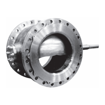
Description
The V150 or V300 Vee-Ball valve with a V-notch ball is used in throttling or on-off service. The V150 valve (figure 1) is a
raised-face flanged construction available in CL150. The V300 valve is a raised-face flanged construction available in
CL300. The splined valve shaft connects to a variety of rotary actuators.
www.Fisher.com
. . . . . . . . . . . . . . . . . . . . . . . .
. . . . . . . . . . . . . . . . . . . . .
. . . . . . . . . . . . . . . . . . . . . . . .
. . . . . . . . . . . . . . . . .
. . . . . . . . . . . . . . .
Figure 1. Fisher V150 and V300 Vee-Ball NPS 16
1
1
1
2
2
5
5
6
6
7
9
10
11
12
13
16
17
18
W6087
18
V150 and V300 Valves
February 2011
Advertisement
Table of Contents

Related Manuals for Emerson Fisher Vee-Ball V150


Summary of Contents for Emerson Fisher Vee-Ball V150
-
Page 1: Table Of Contents
To avoid personal injury or property damage, it is important to carefully read, understand, and follow all the contents of this manual, including all safety cautions and warnings. If you have any questions about these instructions, contact your Emerson Process Management sales office before proceeding. -
Page 2: Valve
Instruction Manual V150 and V300 Valves February 2011 D101957X012 Table 1. Specifications Valve Sizes and End Connection Styles with optional ball rotation for left‐hand mounting is available upon request. V150: NPS 14, 16, and 20 with CL150 raised‐face flanges as shown in table 3 Ball Rotation V300: NPS 14 and 16 with CL300 raised‐face flanges Standard: Ball rotates Counterclockwise to Close... - Page 3 Emerson Process Management sales office. Install the valve with the drive shaft in the horizontal position as shown in figure 1.
- Page 4 Instruction Manual V150 and V300 Valves February 2011 D101957X012 DIMENSION (Min.) VALVE SIZE, CL150 CL150 ASME B16.10 CL300 ASME B16.10 CL300 CL150 CL300 (Short) (Short) ‐ ‐ ‐ ‐ ‐ ‐ ‐ ‐ ‐ Inch 15.00 15.00 6.88 6.00 7.75 5.25 7.00 16.00...
-
Page 5: Maintenance
Instruction Manual V150 and V300 Valves D101957X012 February 2011 WARNING Personal injury could result from packing leakage. Valve packing was tightened before shipment; however, the packing might need some readjustment to meet specific service conditions. Check with your process or safety engineer for any additional measures that must be taken to protect against process media. -
Page 6: Stopping Leakage
Instruction Manual V150 and V300 Valves February 2011 D101957X012 Stopping Leakage For PTFE V‐ring packing, leakage around the packing follower and packing flange (keys 17 and 40) can be stopped by tightening the packing follower nuts (key 20). If the packing is relatively new and tight on the drive shaft (key 6), and if tightening the packing follower nuts does not stop leakage, it is possible that the drive shaft is worn or nicked so that a seal cannot be made. -
Page 7: Ball Seal Replacement
Instruction Manual V150 and V300 Valves D101957X012 February 2011 5. If necessary, remove the bonding strap assembly before attempting to remove the packing (see figure 4). 6. Remove the packing flange and nuts and packing follower (keys 20, 40, and 17). If the valve is equipped with the ENVIRO‐SEAL packing system, refer to the ENVIRO‐SEAL Packing System for Rotary Valves instruction manual (D101643X012) for disassembly. - Page 8 Instruction Manual V150 and V300 Valves February 2011 D101957X012 Figure 3. Packing Arrangements A6063/IL 42B8445-B B2412/IL...
-
Page 9: Disassembly
Instruction Manual V150 and V300 Valves D101957X012 February 2011 Figure 4. Optional Shaft‐to‐Body Bonding Strap Assembly ACTUATOR VALVE BODY 37A6528-A A3143-2/IL VIEW A‐A The flow ring construction does not use a seal (key 11), radial seal (key 37), or wave spring (key 13). Use this procedure to remove the seal protector ring for flow ring constructions, but disregard any instructions calling for the seal and other seal parts. -
Page 10: Assembly
Instruction Manual V150 and V300 Valves February 2011 D101957X012 It might be necessary to remove the HD metal seal by carefully tapping it with a soft punch and hammer. Take care not to damage the seal protector ring surfaces. 4. Inspect, clean, or obtain replacement parts as necessary. Inspect the gasket and sealing surfaces on the valve body (key 1), ball (key 2), ball seal (key 11), and seal protector ring (key 3) for damage. -
Page 11: Bearing And Ball Maintenance
Instruction Manual V150 and V300 Valves D101957X012 February 2011 Figure 6. Flow Ring Construction SEAL PROTECTOR RING E0849 D Install the HD metal seal (key 11) into the seal protector ring (key 3), past the radial seal. While pushing it past the radial seal, make sure the HD metal seal is level. -
Page 12: Disassembly
Instruction Manual V150 and V300 Valves February 2011 D101957X012 Disassembly WARNING When the actuator is removed from the valve, the ball may suddenly rotate, resulting in personal injury. To avoid injury, carefully rotate the ball to a stable position. Once the drive and follower shafts have been removed from the valve body, the ball may fall out of or into the valve body. To avoid personal injury or damage to the sealing surfaces of the ball, provide a hoist to support the ball to prevent it from falling as the shafts are being removed. -
Page 13: Assembly
Instruction Manual V150 and V300 Valves D101957X012 February 2011 Assembly 1. Inspect all sealing surfaces to ensure they are in good condition and without scratches or wear. Thoroughly clean all parts and make sure they are free of oil or grease. 2. - Page 14 Instruction Manual V150 and V300 Valves February 2011 D101957X012 Note 1. See note 1, figure 10. 2. For valves with metal bearings, hold the thrust washer (key 38, figure 10) in place before inserting the drive shaft. Make sure that the ``O'' mark on the shaft aligns with the ``O'' mark on the ball ear, within the ball cavity. Insert the drive shaft (key 6) into the ball.
- Page 15 Instruction Manual V150 and V300 Valves D101957X012 February 2011 Figure 8. Index Mark for Actuator Lever Orientation NOTE: 1. ARROW ON LEVER INDICATES DIRECTION OF ACTUATOR THRUST TO CLOSE VALVE. 5. Installing the pins (key 7): CAUTION The ball might be damaged if it is allowed to hit the flange edge or interior of the valve cavity while it is being lowered into the valve body.
-
Page 16: Actuator Mounting
Instruction Manual V150 and V300 Valves February 2011 D101957X012 D Using a pry bar, insert the bar between the ball ear and the follower shaft side of the valve body. Move the ball tightly towards the packing box side of the valve body, and against the bearing flange or thrust washer. The ball should be centered within the seal cavity. -
Page 17: Determining Open Position
If necessary, it is possible to mount the valve in the left‐hand position with the ball rotating to the top of the valve. This will require a non‐standard ball. The ball rotates clockwise to close. Refer to figure 8, or contact your Emerson Process Management sales office for assistance. -
Page 18: Parts Ordering
Note Neither Emerson, Emerson Process Management, nor any of their affiliated entities assumes responsibility for the selection, use, or maintenance of any product. Responsibility for the selection, use, and maintenance of any product remains with the purchaser and end user. -
Page 19: D101957X012 February
Instruction Manual V150 and V300 Valves D101957X012 February 2011 Figure 10. Fisher V150 and V300 Valve Assembly 43B6886-A/DOC 43B7128‐A... - Page 20 *Recommended spare parts Fisher, Vee-Ball, and ENVIRO-SEAL are marks owned by one of the companies in the Emerson Process Management business division of Emerson Electric Co. Emerson Process Management, Emerson, and the Emerson logo are trademarks and service marks of Emerson Electric Co. All other marks are the property of their respective owners.
Need help?
Do you have a question about the Fisher Vee-Ball V150 and is the answer not in the manual?
Questions and answers