
Related Manuals for Wabtec NI 10R


Summary of Contents for Wabtec NI 10R
- Page 1 NI 10R True RMS Stroomtang Handleiding True RMS Current Clamp Manual Nieaf-Smitt is a brand name of Wabtec NETHERLANDS...
- Page 2 Wabtec Netherlands B.V.. This also applies to accompanying drawings and diagrams. Due to a policy of continuous development Wabtec Netherlands B.V reserves the right to alter the equipment specification and description outlined in this document without prior notice and no part of this publication shall be deemed to be part of any contract for the equipment unless specifically referred to as an inclusion within such contract.
-
Page 3: Table Of Contents
Inhoud Veiligheid Stroomtang beschrijving Specificaties Metingen 4.1 AC/DC stroom 4.2 AC/DC spanning 4.3 Weerstand 4.4 Diodes en continuiteit 4.5 Capaciteit 4.6 Frequentie/duty cycle 4.7 Temperatuur 4.8 Contactloos wisselspanning Functies 5.1 MODE 5.2 REL 5.3 HOLD Batterij vervangen Garantie www.nieaf-smitt.com... -
Page 4: Veiligheid
Veiligheid Internationale veiligheidssymbolen Dit symbool naast een ander symbool of een aansluitpunt geeft Dit symbool naast een ander symbool of een aansluitpunt geeft aan dat de gebruiker de handleiding moet raadplegen voor meer aan dat de gebruiker de handleiding moet raadplegen voor meer informatie. - Page 5 • Controleer of de meetkabels en de meter zelf zijn beschadigd voordat u de meter in gebruik neemt. Zorg ervoor dat beschadigde onderdelen zijn gerepareerd of vervangen voordat u de meter in gebruik neemt. • Wees uiterst voorzichtig wanneer u spanningen meet van meer dan 25 VAC (RMS) of 35 VDC.
-
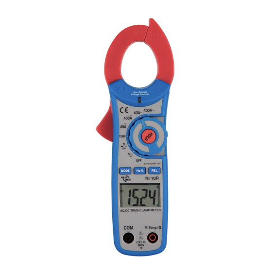
Page 6: Stroomtang Beschrijving
Stroomtang beschrijving Stroomklem Controlelampje voor contactloze meting AC-spanning Trekker Draaischakelaar LCD-scherm Knop HOLD Knop MODE Knop voor Hz en % Knop REL 10. COM-aansluiting 11. V Ω CAP TEMP Hz-aansluiting 12. Batterijdeksel www.nieaf-smitt.com... - Page 7 DC (gelijkstroom) AC (wisselstroom) Minteken AUTO Autobereik modus Diodetest modus •))) Alarmtoon continuïteit HOLD Modus gegevens vasthouden Relatieve modus Frequentie modus 10. % Inschakelduur modus Automatische uitschakeling 12. NμF, mV NμF, mV Meeteenheiden Meeteenheiden Lage batterij spanning Celsius Fahrenheit 16. 8.8.8.8 Meetwaarden tot 4000 (0 t/m 3999) www.nieaf-smitt.com...
-
Page 8: Specificaties
Specificaties Functie Bereik en resolutie Nauwkeurigheid (% vd meting) Wisselstroom (50/60 Hz) 40.00 AAC + (2.5 % + 8 digits) 400.0 AAC + (2.8 % + 5 digits) Gelijkstroom 40.00 ADC + (2.5 % + 5 digits) 400.0 ADC + (2.8 % + 5 digits) Wisselspanning (50-400 Hz) 4.000 VAC 40.00 VAC... - Page 9 Klemopening Geopend circa 30 mm (1.2”) Diode meting Normale teststroom 0.3 mA, normale nullast spanning 3 VDC Drempelwaarde <50 Ω, teststroom < 0.5 mA Continuiteitscontrole Batterij bijna leeg ‘ ‘ wordt weergegeven Overschrijdingsindicatie ‘OL‘ wordt weergegeven Meetsnelheid 2 per seconde, nominaal Ingangsimpedantie 10 MΩ...
-
Page 10: Metingen
Metingen OPMERKING: Lees alle waarschuwingen en voorzorgsmaatregelen in OPMERKING: Lees alle waarschuwingen en voorzorgsmaatregelen in het gedeelte over veiligheid van deze handleiding zorgvuldig voordat het gedeelte over veiligheid van deze handleiding zorgvuldig voordat u deze meter in gebruik neemt. Zet de functieschakelaar op stand OFF u deze meter in gebruik neemt. -
Page 11: Ac/Dc Spanning
4.2 AC/DC spanning metingen Plaats de zwarte meetkabel in de negatieve COM-aansluiting en de rode meetkabel in de positieve V-aansluiting Zet de functieschakelaar in stand V Selecteer AC of DC met behulp van de knop MODE (Modus) Sluit de meetkabels parallel aan op het circuit dat u wilt meten De gemeten spanning wordt weergegeven op het lcd-scherm... -
Page 12: Diodes En Continuiteit
4.4 Diodes en continuïteit meten Plaats de zwarte banaanstekker in de negatieve COM-aansluiting en de rode banaanstekker in de positieve diodeaansluiting Zet de draaischakelaar op stand Ω •))) CAP Druk op de knop MODE (Modus) totdat het scherm wordt weergegeven Raak de meetpunten aan van de diode die u wilt meten. -
Page 13: Frequentie/Duty Cycle
4.6 Frequentie/duty cycle meten Zet de draaischakelaar op stand ‘V’ Plaats de zwarte banaanstekker in de negatieve COM-aansluiting en de rode banaanstekker in de positieve aansluiting Raak de meetpunten aan van het circuit dat u wilt meten De gemeten frequentie wordt weergegeven op het lcd-scherm Temperatuur meten WAARSCHUWING: Ontkoppel beide meetkabels van eventuele WAARSCHUWING: Ontkoppel beide meetkabels van eventuele... -
Page 14: Contactloos Wisselspanning
4.8 Contactloos wisselspanning meten WAARSCHUWING: Risico op elektrocutie Test de spanningsdetector WAARSCHUWING: Risico op elektrocutie Test de spanningsdetector voor gebruik altijd op een circuit waarvan u zeker weet dat er voor gebruik altijd op een circuit waarvan u zeker weet dat er spanning op staat. -
Page 15: Functies
Vervang de batterijen Plaats het batterijdeksel terug Garantie Wabtec Netherlands B.V. geeft gedurende een periode van 12 maanden garantie op het meetsysteem. De garantieperiode gaat in op de dag dat de levering plaatsvindt. De aansprakelijkheid is vastgelegd in de leveringsvoorwaarden van het FME en HE. - Page 16 Content Safety Description Specifications Measurements 4.1 AC/DC current 4.2 AC/DC voltage 4.3 Resistance 4.4 Diode and continuity 4.5 Capacitance 4.6 Frequency or duty cycle 4.7 Temperature 4.8 Non contact voltage Functions 5.1 MODE 5.2 HOLD 5.3 REL Battery replacement Warranty www.nieaf-smitt.com...
-
Page 17: Safety
Safety International safety symbols This symbol, adjacent to another symbol or terminal, indicates the This symbol, adjacent to another symbol or terminal, indicates the user must refer to the manual for further information. user must refer to the manual for further information. This symbol, adjacent to a terminal, indicates that, under normal use, This symbol, adjacent to a terminal, indicates that, under normal use, hazardous voltages may be present... - Page 18 • Remove the battery if the meter is to be stored for long periods • Always discharge capacitors and remove power from the device under test before performing Diode, Resistance or Continuity tests • Voltage checks on electrical outlets can be difficult and misleading because of the uncertainty of connection to the recessed electrical contacts.
-
Page 19: Description
Description Current clamp Non-contact AC voltage indicator light Clamp trigger Rotary function switch LCD display Data hold function MODE select button Hz% Hold button Relative button 10. COM input jack 11. Positive input jacks 12. Battery cover www.nieaf-smitt.com... - Page 20 DC (direct currrent) AC (alternating current) Min sign AUTO Autorange mode Diode test mode •))) Audible continuïty HOLD Data hold mode Relative mode Frequency 10. % Duty cycle mode Auto power off 12. NμF, mV NμF, mV Units of measure list Units of measure list Low battery Celsius...
-
Page 21: Specifications
Specifications Function Range and resolution Accuracy (% of reading) AC current (50/60 Hz) 40.00 AAC + (2.5 % + 8 digits) 400.0 AAC + (2.8 % + 5 digits) DC current 40.00 ADC + (2.5 % + 5 digits) 400.0 ADC + (2.8 % + 5 digits) AC voltage (50-400 Hz) 4.000 VAC... - Page 22 Clamp size Opening 30 mm (1.2”) approx. Diode test Test current 0.3 mA typical, open circuit voltage 3 VDC typical Threshold <50 Ω, test current < 0.5 mA Continuity check Low battery indication ‘ ‘ is displayed Overrange indication ‘OL‘ is displayed Measurements rate 2 per second, nominal Input impedance...
- Page 23 Measurements Read and understand all warning and precaution statements listed Read and understand all warning and precaution statements listed in the safety section of this operation manual prior to using this in the safety section of this operation manual prior to using this meter.
- Page 24 4.2 AC/DC voltage measurements Insert the black test lead into the negative COM terminal and the red test lead into the positive V terminal Set the function switch to the V position Select AC or DC with the MODE button Connect the test leads in parallel to the circuit under test Read the voltage measurement on the...
- Page 25 4.4 Diode and Continuity measurements Insert the black test lead banana plug into the negative COM jack and the red test lead banana plug into the positive diode jack Turn the rotary switch to the Ω •))) CAP position Press the MODE button until appears in the display Touch the test probes to the diode under test.
- Page 26 4.6 Frequency/duty cycle measurements Set the rotary function switch to “V” position Insert the black lead banana plug into the negative COM jack and the red test lead banana plug into the positive jack Touch the test probe tips to the circuit under test Read the frequency on the display Temperature measurements WARNING: To avoid electric shock, disconnect...
-
Page 27: Non Contact Voltage
4.8 Non-Contact AC voltage measurements Touch the probe tip to the hot conductor or insert into the hot side of the electrical outlet If AC voltage is present, the detector light will illuminate NOTE: The conductors in electrical cord sets are often twisted. For best NOTE: The conductors in electrical cord sets are often twisted. -
Page 28: Functions
Re-assemble the meter Warranty Wabtec Netherlands B.V. guarantees the tester for a period of 12 months. The period of warranty will be effective at the day of delivery. The warranty clauses and the stipulations regarding liability in terms of delivery (FME and HE).
Need help?
Do you have a question about the NI 10R and is the answer not in the manual?
Questions and answers