Table of Contents
Advertisement
Quick Links
MM650 CAT IV True RMS Digital
Multimeter with LoZ
Introduction
The Triplett MM650 features True RMS measurements for more
accurate AC readings and a Low Z setting for eliminating false
readings caused by "ghost" voltages. Functions include AC/DC
voltage and current, resistance, continuity, capacitance, frequency,
duty cycle, temperature, and diode test. The MM650 also offers the
added convenience of a built-in LED flashlight. This meter is fully
1.800.561.8187
User Manual
www.
information@itm.com
.com
Advertisement
Table of Contents

Related Manuals for Triplett MM650


Summary of Contents for Triplett MM650
- Page 1 AC readings and a Low Z setting for eliminating false readings caused by “ghost” voltages. Functions include AC/DC voltage and current, resistance, continuity, capacitance, frequency, duty cycle, temperature, and diode test. The MM650 also offers the added convenience of a built-in LED flashlight. This meter is fully 1.800.561.8187 information@itm.com...
- Page 2 tested and calibrated and, with proper use, will provide many years of reliable service. WARNINGS • Read, understand and follow Safety Rules and Operating Instructions in this manual before using this meter. • The meter’s safety features may not protect the user if not used in accordance with the manufacturer’s instructions.
- Page 3 1.800.561.8187 information@itm.com www. .com...
-
Page 4: International Safety Symbols
International Safety Symbols Potential danger. Indicates the user must refer to the manual for important safety information Indicates hazardous voltages may be present Equipment is protected by double or reinforced insulation Indicates the terminal(s) so marked must not be connected to a circuit where the 1000V voltage with respect to earth ground exceeds the maximum safety rating of the meter Safety Category Ratings... -
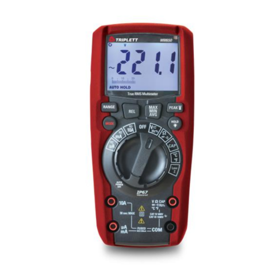
Page 5: Meter Description
Meter Description 1. LCD display 2. RANGE button 3. REL button 4. MODE button 5. Rotary function switch 6. 10A input jack 7. µA, mA input jack 8. COM input jack 9. V/Ω/, Hz/ %, Diode, Continuity, Cap, °C/F Input Jack 10. -
Page 6: Display Description
Display Description 1.800.561.8187 information@itm.com www. .com... -
Page 7: Range Button
Operating Instructions RANGE Button The Auto Range mode automatically selects the proper range for the measurement being made and is generally the best mode for most applications. For measurement situations requiring that a range be manually selected, perform the following: 1. -
Page 8: Max/Min/Avg Button
MAX/MIN/AVG Button 1. Momentarily press the MAX/MIN/AVG button to activate the MAX/MIN/Average mode. “MAX” will appear on the LCD display and the meter will display and hold the highest reading. The meter will update the reading when a higher “max” occurs. 2. -
Page 9: Hold/Backlight Button
1. Press and hold the PEAK button until “Peak MAX” appears on the LCD display. The meter will display the highest reading and will update the reading when a higher positive peak occurs. To view highest negative peak, press the PEAK button for approximately one second. -
Page 10: Ac/Dc Voltage Measurements
WARNING: Risk of electrocution. High-voltage circuits, both AC and DC, are very dangerous and should be measured with great care. 1. ALWAYS turn the function switch to the OFF position when the meter is not in use. 2. If “OL” appears in the display during a measurement, the value exceeds the range you have selected. -
Page 11: Frequency And % Duty Cycle Measurements
Frequency and % Duty Cycle Measurements WARNING: Observe all safety precautions when working on live voltages. Do not measure frequency or % duty cycle on circuits that exceed 600V. Set the rotary function switch to the V HZ % position. 2. -
Page 12: Ac/Dc Current Measurements
Set the rotary function switch to the Low Z position. 2. Press the MODE button to select AC or DC voltage. The AC “~” or DC “” symbol will appear on the LCD display. 3. Insert the black test lead into the COM input jack and the red test lead into the V input jack. - Page 13 For current measurements up to 6000 uA set the rotary function switch to the uA position and insert the red test lead into the uA/mA input jack. Press the MODE button to select AC or DC current. The AC “~” or DC “”...
-
Page 14: Resistance Measurements
RESISTANCE MEASUREMENTS WARNING: To avoid electric shock, disconnect power to the unit under test and discharge all capacitors before taking any resistance measurements. Remove the batteries and unplug the line cords. 1. Set the function switch to the Ω position. 2. -
Page 15: Diode Test
4. Touch the test probe tips to the circuit or wire you wish to check. 5. If the resistance is less than approximately 35 , the audible signal will sound. If the circuit is open, the display will indicate “OL”. DIODE TEST 1. -
Page 16: Temperature Measurements
negative COM jack. Insert the red test lead banana plug into the positive V jack. 3. Touch the test leads to the capacitor to be tested. 4. Read the capacitance value in the display TEMPERATURE MEASUREMENTS 1. Set the function switch to the green Temp position. 2. -
Page 17: Battery Replacement
Battery Replacement WARNINGS: To avoid electric shock, remove the test leads from the meter before removing the battery/fuse cover. 1. Lift up the tilt stand. 2. Loosen the Phillips screw(s) on the battery/fuse cover. 3. Remove the battery/fuse cover. 4. Replace the batteries with four AAA batteries. -
Page 18: Fuse Replacement
Fuse Replacement WARNINGS: To avoid electric shock, remove the test leads from the meter before removing the battery/fuse cover. 1. Lift up the tilt stand. 2. Loosen the Phillips screw(s) on the battery/fuse cover. 3. Remove the battery/fuse cover. 4. Gently remove fuse and install new fuse into the holder. -
Page 19: Specifications
Specifications Accuracy is stated at 65°F to 83°F (18°C to 28°C), less than 70% relative humidity Function Range Resolution Accuracy ± (% of reading + digits) AC Voltage 6.000V 60.00V 10mV ±(1.0% +5 digits) 600.0V 0.1V 1000V ±(1.5% +5 digits) All AC voltage ranges are specified from 5% of range to 100% of range Input Protection: 1000V AC RMS or 1000V DC... - Page 20 Function Range Resolution Accuracy ± (% of reading + digits) Frequency 9.999Hz 0.001Hz 99.99Hz 0.01Hz ±(1.0% +5 digits) 999.9Hz 0.1Hz 9.999kHz Input Protection: 600V AC RMS or 600V DC Sensitivity: >8V RMS Function Range Resolution Accuracy ± (% of reading + digits) Duty Cycle 20.0% to 80.0% 0.1%...
-
Page 21: Maintenance
Function Range Resolution Accuracy ± (% of reading + digits) Resistance 600.0Ω 0.1Ω 6.000kΩ 1Ω ±(1.5% +5 digits) 60.00kΩ 10Ω 600.0kΩ 100Ω 6.000MΩ 1kΩ ±(2.0% +10 digits) 60.00MΩ 10kΩ Input Protection: 600V AC RMS or 600V DC Function Range Resolution Accuracy ± (% of reading + digits) Capacitance 60.00nF... - Page 22 Warranty Information Triplett / Jewell Instruments extends the following warranty to the original purchaser of these goods for use. Triplett warrants to the original purchaser for use that the products sold by it will be free from defects in workmanship and material for a period of (3) three years from the date of purchase.
Need help?
Do you have a question about the MM650 and is the answer not in the manual?
Questions and answers