SMAR FY302 Operation, Maintenance And Instructions Manual
Fieldbus valve positioner
Hide thumbs
Also See for FY302:
- Installation, operation and maintanance manual (66 pages) ,
- Installation, operation and maintenance manual (44 pages) ,
- Operation, maintenance & instruction manual (79 pages)
Table of Contents
Advertisement
Quick Links
Advertisement
Table of Contents

Related Manuals for SMAR FY302


Summary of Contents for SMAR FY302
- Page 3 The FY302, like the rest of the 302 family, has several Function Blocks built in, like PID controller, Input Selector and Splitter/Output Selector, eliminating the need for separate device. This takes to reduced communication and thereby less dead-time and tighter control, not to mention the reduction in cost.
- Page 4 Smar provides specific training to instruct and qualify such professionals. However, each country must comply with the local safety procedures,...
-
Page 5: Table Of Contents
Table of Contents TABLE OF CONTENTS SECTION 1 - INSTALLATION ........................ 1.1 GENERAL................................1.1 MOUNTING ................................1.1 PNEUMATIC CONNECTIONS ..........................1.4 DIMENSIONAL DRAWINGS ..........................1.6 ELECTRONIC HOUSING ROTATING ......................... 1.7 ELECTRIC WIRING .............................. 1.8 TOPOLOGY AND NETWORK CONFIGURATION....................1.9 INTRINSIC SAFETY BARRIER .......................... 1.11 JUMPER CONFIGURATION .......................... - Page 6 FY302 – Operation, Maintenance, and Instructions Manual PACKAGE CONTENT ............................4.5 EXPLODED VIEW ..............................4.6 SPARE PARTS LIST ............................4.7 DETAILED CODE WHEN ORDERING OF SPARE PARTS ................. 4.9 SECTION 5 - TECHNICAL CHARACTERISTICS ................... 5.1 FUNCTIONAL SPECIFICATIONS ........................5.1 PERFORMANCE SPECIFICATIONS ........................
- Page 7 Installation Flowchart Installation Flowchart...
- Page 8 FY302 – Operation, Maintenance, and Instructions Manual VIII...
-
Page 9: Section 1 - Installation
Two supports are required for mounting, one for the magnet and the other for the positioner itself. Smar may supply them both since they are specified in the order code. (See Table 5.2). - Page 10 FY302 – Operation, Maintenance, and Instructions Manual Install the positioner support on the actuator. The actuator should be in accordance with standard VDI/VDE 5845, thus tighten the four screws with the lock washers on the standard support. For special supports, refer to specify instructions. After installing the support on the actuator, it is possible to mount the positioner on the support by means of the four screws with lock washers.
- Page 11 Installation Linear Movement Install the magnet on the valve stem using the magnet support (See Figure 1.3). Install the positioner support on the actuator. The actuator support may be secured in place as per standard NAMUR/IEC 536-4 or in accordance with user specified boring. Install the positioner on the support and tighten the four screws in the threaded bores located on the side opposite to the pressure gages (See Figure 1.3).
-
Page 12: Pneumatic Connections
Air supply pressure to the FY302 shall be between 1.4 bar (20 psi) and 7 bar (100 psi). In case such requirements cannot be fulfilled, the use of an air pressure regulator is acceptable. - Page 13 Make sure that sealant does not enter the positioner. There are five exhaust outputs in the FY302, all of them fitted with filters. It is very important that such outputs are neither blocked nor obstructed, because the air must circulate freely. In case of painting the Positioner block, remove the filters to prevent them from clogging with the paint All filters shall be inspected to make sure they will not obstruct the outputs.
-
Page 14: Dimensional Drawings
FY302 – Operation, Maintenance, and Instructions Manual Dimensional Drawings All dimensions are in mm (in) VALVE POSITIONER Leave, at least, a 150mm (5.8 in) space, for zero and span adjustments with the magnetic tool. (3.27) (4.45) SOCKET SET PLUG ELECTRICAL... -
Page 15: Electronic Housing Rotating
Installation REMOTE HALL SENSOR Figure 1.5 - FY302 Dimensional Drawings NOTE Included in the package content the centralizer device of rotary magnet. Electronic Housing Rotating The electronic housing can be rotated in order to have a better position of the digital display. To rotate it, use the housing rotation set screw. -
Page 16: Electric Wiring
For convenience there are three ground terminals: one inside, near the terminal block and two externals, located close to the conduit entries. The FY302 uses 31.25 Kbits/s voltage mode with physical current modulation. All other equipment on the bus must use the same modulation type and be connected in parallel along the same wire pair. -
Page 17: Topology And Network Configuration
NOTE Please refer to the Foundation Fieldbus General Manual for further details. The FY302 is reverse polarity protected and can support up to ±35 Vdc without damage, but it does not operate when polarity is reversed. Topology and Network Configuration Bus topology (See Figure 1.10) and tree topology (See Figure 1.11) are supported. - Page 18 FY302 – Operation, Maintenance, and Instructions Manual 24VDC OUT 1 Fieldbus H1 OUT 2 Spur Fieldbus H1 OUT 3 Fieldbus H1 OUT 4 Fieldbus H1 Terminator Enabled FUSE 2,5A Junction smar Shield PS302 PSI302 FAIL Terminator FAIL 1 FAIL 2...
-
Page 19: Intrinsic Safety Barrier
Use of DF47-17 is recommended. Jumper Configuration In order to work properly, the jumpers J1 and W1 located in the FY302 main electronic board must be correctly configured. This jumper enables the simulation mode parameter in the AO block. -
Page 20: Rotary And Linear Magnet
FY302 – Operation, Maintenance, and Instructions Manual COMPRESSOR INTAKE CONDENSATE AIR RECEIVER AFTERCOOLER SEPARATOR WITH DRAIN WITH DRAIN COMPRESSOR Figure 1.11 - Air Supply System OIL AND WATER DRY AIR MIST PREFILTER AFTERFILTER DRYER WITH DRAIN Figure 1.12 - Air Quality Conditioning System Rotary and Linear Magnet Magnet models are linear and rotary, for utilization on linear and rotary actuators. -
Page 21: Remote Hall Sensor
Therefore, when installing the cable inside the conduit (maximum limit 20 meters length) keep it away from possible sources of induction and/or magnetic interference. The cable supplied by Smar is shielded for excellent protection against electromagnetic interference, but despite this protection avoid the cable sharing the same conduit with other cables. -
Page 22: Installation In Hazardous Areas
FY302 – Operation, Maintenance, and Instructions Manual Installation in Hazardous Areas Refer to Appendix A for certifications information. 1.14... -
Page 23: Section 2 - Operation
Section 2 OPERATION Functional Description - Output Module The main parts of the output module are the pilot, servo, Hall Effect sensor and the output control circuit. The control circuit receives a digital setpoint signal from the CPU and a feedback signal from the Hall Effect sensor. -
Page 24: Functional Description - Electronics
FY302 – Operation, Maintenance, and Instructions Manual Functional Description - Electronics Refer to the block diagram. The function of each block is described below. Figure 2.2 - FY302 Block Diagram... - Page 25 Power Supply The positioner circuit receives supply from a 9 to 32 Vdc power supply. A special power supply on an intrinsically safe bus must be used. Smar has the DF52 (intrinsically safe) power supply for this application. Display Controller Receives data from the CPU and drives the (LCD) Liquid Crystal Display.
-
Page 26: Introduction To Fieldbus Application
These blocks are models of the functionality that the FY302 provides for a control system. They can loosely be said to make up part of the application that is performed in the FY302. Generally, these blocks can be said to use an algorithm and contained parameters to process input parameters producing output parameters. -
Page 27: The Local Indicator
LCD display should be configured in the display block. During normal operation, the FY302 remains in the monitoring mode and the display will always indicate the variable of monitoring configured in the display block. It is recommended configuring the position of the valve in % (percentage). - Page 28 FY302 – Operation, Maintenance, and Instructions Manual Figure 2.4 - Typical Indicator...
-
Page 29: Transducer Block
One of the many advantages of Fieldbus is that device configuration is independent of the configurator. A third-party terminal or operator console may configure the FY302. Any particular configurator is therefore not addressed here. The FY302 contains one output transducer block, one resource block, one display transducer block and function blocks. Transducer Block Transducer block insulates function block from the specific I/O hardware, such as sensors, actuators. -
Page 30: Transducer
FY302 – Operation, Maintenance, and Instructions Manual Transducer Description The fieldbus positioner transducer receives the demanded valve position FINAL_VALUE from the AO block and uses it as a setpoint for a PID servo-positioning algorithm with adjustable gains SERVO_GAIN and SERVO_RESET. The transducer block also makes the corrected actual position sensor reading RETURN available to the AO block. - Page 31 Configuration Index Parameter Valid Range Default Value Units ACT_SN None VALVE_MAN_ID None VALVE_MODEL_NUM Null None VALVE_SN None VALVE_TYPE Linear/Rotary Liner None XD_CAL_LOC Null None XD_CAL_DATE Unspecified None XD_CAL_WHO Null None CAL_POINT_HI -10.0 - 110.0% CAL_POINT_LO -10.0 - 100.0% CAL_MIN_SPAN CAL_UNIT CAL_METHOD Factory None...
- Page 32 FY302 – Operation, Maintenance, and Instructions Manual Index Parameter Valid Range Default Value Units CAL_POINT_HI_FACTORY 100.0 CAL_POINT_LO_FACTORY SETUP Enable/Disable Disable None FEEDBACK _CAL CAL_CONTROL Enable/Disable Disable None RETURN POT_KP None POT_DC None MAGNET_SIZE None ANALOG_LATCH TRD None MAIN_LATCH None DIGITAL_TEMPERATURE...
- Page 33 Configuration Transducer Block Parameters - Description Index Parameter Description ST_REV Indicates the level of static data. TAG_DESC Description of Transducer Block. STRATEGY This parameter is not checked and processed by Transducer Block. ALERT_KEY Number of identification in the plant. MODE_BLK Indicates the operation mode of Transducer Block.
- Page 34 FY302 – Operation, Maintenance, and Instructions Manual SERVO_PID_INTEGRAL_PER Percent integral value for the servo PID. SERVO_PID_MV_PER Internal value. MODULE_SN Output transducer module serial number. COEFF_HALL_POL0 Position sensor polynomial coefficient 0. COEFF_HALL_POL1 Position sensor polynomial coefficient 1. COEFF_HALL_POL2 Position sensor polynomial coefficient 2.
- Page 35 Configuration USER_DA_CAL_POINT_HI Digital analog value for output in a highest calibration point. USER_DA_CAL_POINT_LO Digital analog value for output in a lowest calibration point. DIGITAL_HALL_VALUE Raw actual position feedback value. SETUP_PROGRESS Shows the auto set up progress. HALL_OFFSET The value after completing self offset actual position sensor calibration. ORDERING_CODE Ordering code for the product.
- Page 36 FY302 – Operation, Maintenance, and Instructions Manual Transducer Block Parameters - Attributes Index Parameter Data Type Store Access ST_REV Unsigned16 TAG_DESC VisibleString STRATEGY Unsigned16 ALERT_KEY Unsigned8 MODE_BLK DS-69 BLOCK_ERR Bit String UPDATE_EVT DS-73 BLOCK_ALM DS-72 TRANSDUCER_DIRECTORY Array of Unsigned16 TRANSDUCER_TYPE...
- Page 37 Configuration Index Parameter Data Type Store Access COEFF_SENS_TEMP_POL2 Float COEFF_SENS_TEMP_POL3 Float COEFF_SENS_TEMP_POL4 Float POLYN_SENS_TEMP_VERSION Unsigned8 CAL_TEMPERATURE Float CAL_DIGITAL_TEMPERATURE Float CHARACTERIZATION_TYPE Unsigned8 CURVE _BYPASS Unsigned8 CURVE _LENGTH Unsigned8 CURVE _X Array of Float CURVE _Y Array of Float CAL_POINT_HI_ BACKUP Float CAL_POINT_LO_ BACKUP Float CAL_POINT_HI_FACTORY...
-
Page 38: How To Configure A Transducer Block
This process is necessary to find the position values at which the valve is considered fully open or close. This operation can be done using the SYSCON or the local adjustment. The FY302 automatically finds the fully open and closed positions of a valve, but the user may also set a narrower range of operation should he like to. - Page 39 Configuration The "disable" denotes that the setup operation was completed. Figure 3.3 - Disabling the Auto-Setup Operation The setup progress can be followed by watching the parameters SETUP_PROGRESS. It goes from 0 to 100%. SETUP_PROGRESS goes from 0 to 100%. Figure 3.4 - Setup Progress The setup process stuck sometimes because of wrong parameter configuration or a problem in the positioner assembly.
-
Page 40: Calibration
It is possible to calibrate the positioner by parameters CAL_POINT_LO and CAL_POINT_HI. Let’s take the lower value as an example: Write 0% in parameter CAL_POINT_LO. For FY302 it should be always 0%. Simply by writing in this parameter, the trim procedure is initialized. - Page 41 Configuration This parameter indicates where the positioner The desired value should be when the should be entered. setpoint lower value is Figure 3.6 - Calibrating Low Range Value Point Check the position showed in the local indicator. If it is different of 0%, write it in the parameter FEEDBACK_CAL.
- Page 42 Write this value in FEEDBACK_CAL Select DISABLE to the CAL_CONTROL, to finish the procedure. For the upper value, write 100% in parameter CAL_POINT_HI. For FY302 it should be always 100%. Simply by writing in this parameter, the trim procedure is initialized.
-
Page 43: Sensor Pressure
Configuration In order to end the trim procedure, select “DISABLE” in CAL_CONTROL parameter. The enable option indicates that the This parameter calibration process is ends the calibration being done. In order to procedure. finalize its procedure, the user should set it to disable. -
Page 44: Flow Characterization
FY302 – Operation, Maintenance, and Instructions Manual In order to make a good calibration, the valve should be opened totally (out1 with maximum pressure for the sensor out1 trim) and the valve should be closed totally (out2 with maximum pressure for sensor out2 trim). - Page 45 Configuration L = Characterization Factor TYPE LINEAR EP25 EP33 EP50 QO25 0.27 QO33 0.24 QO50 0.19 This parameter contains the These values are coordinates X. in percentage of position value before the curve. Figure 3.15 - Configuring the Table for Flow Characterization - X points This parameter contains the These values are in...
-
Page 46: Temperature Calibration
"Programming Using Local Adjustment". It is significantly the resources on this transducer display, also all the Series 302 field devices from Smar have the same methodology to handle with it. So, since the user has learned once, will be capable to handle all kind of field devices from Smar. -
Page 47: Definition Of Parameters And Values
Configuration All function block and transducers defined according to Foundation Fieldbus have a description of their features written on binary files, by the Device Description Language. This feature permits that third-parties configurator enabled by Device Description Service technology can interpret these features and make them accessible to configure. - Page 48 FY302 – Operation, Maintenance, and Instructions Manual Figure 3.19 - Parameters for Local Adjustment Configuration Figure 3.20 - Parameters for Local Adjustment Configuration Figure 3.21 - Parameters for Local Adjustment Configuration 3.20...
-
Page 49: Calibrating Using Local Adjustment
Configuration The option “update” should be selected in order to execute the This parameter updates update of local the local adjustment adjustment programmning tree programming tree. configured on each After its operation all device. the parameters selected will be shown on the LCD display. - Page 50 FY302 – Operation, Maintenance, and Instructions Manual In order to Place the start the magnetic tool in local “S” orifice and wait adjustment, during 5 seconds. place the magnetic tool in “Z” Figure 3.23 - Step 1 - FY302 Insert the magnetic tool in “S”...
- Page 51 Configuration Figure 3.26 - Step 4 - FY302 Figure 3.27 - Step 5 - FY302 Figure 3.28 - Step 6 - FY302 3.23...
- Page 52 FY302 – Operation, Maintenance, and Instructions Manual Figure 3.29 - Step 7 - FY302 NOTE Every time the Auto-Setup is used it is necessary to save it via Syscon, and to write in the Backup-Restore parameter of the transducer block the sensor Data Backup option.
-
Page 53: Block Type Availability And Initial Block Set
The table below shows how powerful and flexible the Smar devices are. For example, the user may instantiate up to 20 blocks selected from 17 block types (algorithms) in a field device as FY302. Indeed, it means that almost all control strategy may be implemented using only the Smar field devices. - Page 54 FY302 – Operation, Maintenance, and Instructions Manual 3.26...
-
Page 55: Section 4 - Maintenance Procedures
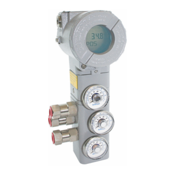
Equipment installed in hazardous atmospheres must be inspected in compliance with the IEC60079-17 standard. FY302 Fieldbus to Valve Positioners are extensively tested and inspected before delivery to the end user. Nevertheless, during their design and development, consideration was given to the possibility of repairs by the end user, if necessary. - Page 56 FY302 – Operation, Maintenance, and Instructions Manual DIAGNOSTICS SYMPTOM PROBABLE ERROR SOURCE Positioner Connections Check wiring polarity and continuity. POSITION Power Supply SHOWN ON DISPLAY Check the minimum voltage signal equal 9 Volts. Electronics Failure Check circuit boards for bad connections and replace them for spare boards.
- Page 57 Maintenance Procedures Figure 4.1 – FY301 Disassembled Maintenance – Mechanical Parts Verify if the spool valve is moving freely. Verify if the spool valve is not obstructed with dirty. Verify if there is any obstruction inside the FY pneumatic block and at the exhausts. Verify if the diaphragm integrity.
- Page 58 Then, select Edit Area. In your area, on the toolbar, select the options Online Mode (ON icon) and Details (glasses icon). After that, still on the toolbar, select the Search option and then Find. Locate the desired FY302 equipment tag.
- Page 59 Maintenance Procedures After locating the device, click the + symbol beside it until you find the Transducer option. Right-click it and select Online Characterization. Find the DIGITAL HALL-VALUE and PIEZO_ANALOG _VOLTAGE, VALUE parameters. Hall values should be as close as possible to 32768 to ±2000;...
-
Page 60: Disassembly Procedure
FY302 – Operation, Maintenance, and Instructions Manual If values are outside this range, realign the magnet. If the setup is not completed and the Hall value is around 65000, it is not being read, the defect may be in the Hall position sensor or in the Analog Board. -
Page 61: Restriction Cleaning Procedure
NOTE To perform the calibration of piezoelectric of the Positioner, refer to the manual of the FYCAL - Calibration Device for Pressure Transducer, available at https://www.smar.com/en/. Restriction Cleaning Procedure The air flows to the nozzle through a restriction. Verify from time to time the restriction cleaning to assure a positioner good performance. -
Page 62: Change Of The Filter Elements
FY302 – Operation, Maintenance, and Instructions Manual Remove the o-ring’s with an appropriate tool; Dive the part in petroleum base solvent and dry it with compressed air (apply the compressed air directly in the smaller orifice for the air to get out through the bigger orifice);... -
Page 63: Electronic Circuit
We suggest its use together with a sealant over the thread followed by a firm tightening. Also make sure the two large housing covers are securely tightened. WARNING The standard plug provided with Smar positioner do not have an Ex-d certification. Package Content When receiving the equipment, verify the package content. - Page 64 FY302 – Operation, Maintenance, and Instructions Manual NOTES 1) When choosing the Remote Sensor version, an additional "L" form support for a 2" tube will be included for fixing the FYRemote (if the FY301 is specified WITH the Fixing Support option). To fix the Remote Sensor to the actuator, it is necessary to specify the BFY according to the ordering code in this manual.
-
Page 65: Exploded View
Maintenance Procedures Exploded View Figure 4.4 - Exploded View 4.11... -
Page 66: Spare Parts List
FY302 – Operation, Maintenance, and Instructions Manual Spare Parts List SPARE PARTS LIST CATEGORY PARTS DESCRIPTION POSITION CODE (NOTE 4) HOUSING (NOTE 1) 400-1314-3F (NOTE 6) 400-1307 (NOTE 6) COVER (INCLUDES O-RING) 1 and 13 Cover Locking Bolt 204-0120 Sensor Locking Bolt (M6 Without Head Screw) - Page 67 6) For code detailed, use the tables below. 7) Access https://www.smar.com/en/support, in General Support, look for Compatibility Note and consult the document 8) The spare part 400-1484, Internal Hexagonal Plug 1/2" NPT SST316 BR-Ex-d, was standardized in SST316 material and will be used in all line of housings (aluminum, copper free aluminum or SST316).
-
Page 68: Detailed Code When Ordering Of Spare Parts
FY302 – Operation, Maintenance, and Instructions Manual Detailed Code When Ordering of Spare Parts DETAILED CODE WHEN ORDERING OF SPARE PARTS CODE DESCRIPTION 400-1314-3F HOUSING; FY302 Option Electrical Connection ½ NPT M20 X 1,5 PG13,5 Option Material Aluminum (IP/Type) Stainless Steel (IP/Type) - Page 69 Stainless Steel (IP/TYPE) Option Painting Gray Munsell N 6,5 Without Painting Safety Blue Epoxy - Electrostatic Painting Option Standard of Manufacture Smar Option Hall Remote Sensor Standard Mounting (Without Hall Remote Sensor) Remote Mounting (adapted for Remote Sensor) Option Special Sensor...
- Page 70 FY302 – Operation, Maintenance, and Instructions Manual DETAILED CODE WHEN ORDERING OF SPARE PARTS CODE DESCRIPTION 400-1318 Piezo Base Set; FY30X Option Indication Gage Without Gage 01 Gage – Input Option Material Aluminum (IP/TYPE) Stainless Steel (IP/TYPE) Option Painting Gray Munsell N 6,5...
- Page 71 Stainless Steel (IP/TYPE) Option Painting Gray Munsell N 6,5 Without Painting Safety Blue Epoxy - Electrostatic Painting Option Standard of Manufacture Smar 400-1321 TYPICAL ORDERING CODE * Choose the desired option. DETAILED CODE WHEN ORDERING OF SPARE PARTS CODE DESCRIPTION 400-1322 Remote Extension Set;...
- Page 72 FY302 – Operation, Maintenance, and Instructions Manual 4.18...
-
Page 73: Section 5 - Technical Characteristics
Section 5 TECHNICAL CHARACTERISTICS Functional Specifications Travel Linear Motion: 3 - 100 mm. Rotary Motion: 30 - 120° Input Signal Digital only. Fieldbus, 31.25 Kbits/s voltage mode with bus power. Output Output to actuator 0 -100% supply air pressure. Single or double action. Power Supply Bus powered: 9-32 Vdc. -
Page 74: Performance Specifications
FY302 – Operation, Maintenance, and Instructions Manual Performance Specifications Resolution ≤ 0.1% F.S. Repeatibility ≤ 0.1% F.S. Hysteresis ≤ 0.1% F.S. Consumption 0.35 Nm/h (0.20 SCFM) at 1.4 bar (20 psi) supply. 1.10 Nm/h (1.65 SCFM) at 5.6 bar (80 psi) supply. -
Page 75: Ordering Code
TYPICAL MODEL NUMBER FY302 NOTES (1) Consult Smar for applications in classified areas. (5) Certification Ex-d for INMETRO. (2) IPW/TYPEX tested for 200 hours according to NBR 8094 / ASTM B 117 standard. (6) When choosing the Remote Sensor version, an additional "L" form support for a (3) Options not certified for hazardous locations. - Page 76 Leave it blank for no optional items TYPICAL MODEL NUMBER (1) When choosing the remote sensor version, an additional “L” shape bracket is included, for 2” tube mounting. (2) For customized mounting bracket, for different brands and models, please, consult Smar website: https://www.smar.com/brasil/produto/fy300series-posicionador- inteligente-de-valvulas...
-
Page 77: Appendix A - Certifications Information
Appendix A CERTIFICATIONS INFORMATION European Directive Information Consult www.smar.com for the EC declarations of conformity for all applicable European directives and certificates. ATEX Directive (94/9/EC) – “Electrical equipment and protective system intended for use in potential explosive atmospheres” The EC-Type Examination Certificate had been released by Nemko AS (CE0470) and/or DEKRA EXAM GmbH (CE0158), according to European Standards. -
Page 78: Hazardous Locations Approvals
Entity parameters at terminals “+” and “-”: Vmax = 24 V, Imax = 250 mA, Pmax = 5.32 W, Ci = 5 nF, Li = 12 uH, when connected as per Smar Installation Drawing 102A0836; T Code T3C @ Max Ambient 40 Deg C; MWP 100 psi. -
Page 79: Nemko (Norges Elektriske Materielkontroll)
Certifications Information Non Incendive (FM 3D9A2.AX and 3015629) NI Class I, Division 2, Groups A, B, C and D Environmental Protection (FM 3007267, 3D9A2.AX and 3015629) Option: Type 4X or Type 4 Special conditions for safe use: Entity Parameters Fieldbus Power Supply Input (report 3015629): Vmax = 24 Vdc, Imax = 250 mA, Pi = 1.2 W, Ci = 5 nF, Li = 12 uH Vmax = 16 Vdc, Imax = 250 mA, Pi = 2 W, Ci = 5 nF, Li = 12 uH Temperature Class T4... - Page 80 FY302 – Operation, Maintenance and Instructions Manual Protection by enclosure (CEPEL 00.0017) Ex tb, Group IIIC, Temperature Class T135ºC/T100ºC/T85ºC, EPL Db Ambient Temperature: -20 to 65 ºC for T135ºC -20 to 50 ºC for T100ºC -20 to 40 ºC for T85ºC Explosion Proof (CEPEL 98.0008)
-
Page 81: Identification Plate
Certifications Information Identification Plate CSA (Canadian Standards Association) FM Approvals (Factory Mutual) NEMKO (Norges Elektriske MaterielKontroll) / EXAM (BBG Prüf - und Zertifizier GmbH) CEPEL (Centro de Pesquisa de Energia Elétrica) - Page 82 FY302 – Operation, Maintenance and Instructions Manual...
-
Page 83: Control Drawing
Certifications Information Control Drawing FM Approvals (Factory Mutual) - Page 84 FY302 – Operation, Maintenance and Instructions Manual CSA (Canadian Standards Association)
- Page 85 Certifications Information...
- Page 86 FY302 – Operation, Maintenance and Instructions Manual A.10...
-
Page 87: Appendix B - Srf - Service Request Form
Company: _____________________________________________________________________________________________________ Contact: ______________________________________________________________________________________________________ Title: _________________________________________________________________________________________________________ Section: ______________________________________________________________________________________________________ Phone: __________ _________________________ __________ _________________________ Extension:____________________ E-mail: _________________________________________________________________________ Date: ______/ ______/ __________ For warranty or non-warranty repair, please contact your representative. Further information about address and contacts can be found on https://www.smar.com/en/contact-us. -
Page 88: Returning Materials
FY302 – Operation, Maintenance and Instructions Manual Returning Materials Should it become necessary to return the positioner and/or configurator to SMAR, simply contact our office, informing the defective instrument serial number, and return it to our factory. In order to speed up analysis and solution of the problem, the defective item should be returned with a description of the failure observed, with as much details as possible. - Page 89 APPENDIX MOUNTING BRACKET FOR POSITIONER – LINEAR STROKE VALVE MOUNTING INSTRUCTIONS 1 –Attach the magnet to the magnet bracket support before connect them to the valve stem. 2 - The stem nuts should be used to fasten the magnet bracket. 3 –...
- Page 90 Mounting Instructions 4 – Tighten the hex screw that join the two parts of the magnet bracket. It will avoid sliding of the two parts of the bracket during the fastening of the stem nuts. 5 – Tighten the stem nuts. 6 –...
- Page 91 BFY – MOUNTING BRACKET FOR POSITIONER FY 7 – Adjust the clamps according to the width of the yoke and tighten the bolts finger tight. 8 – Mount the positioner back plate. Tighten the nuts finger tight. 9 – Use the plate as a guidance to adjust the position of the positioner so that the back plate is about 1 mm apart from the magnet.
- Page 92 Mounting Instructions 10 – Fasten the nuts to fix the positioner bracket to the yoke. If the actuator is pillar type, fasten the U- clamp nuts. 11 – Mount the positioner to the plate and tighten the hex screws. You can take the back plate apart to facilitate the assembling.
- Page 93 BFY – MOUNTING BRACKET FOR POSITIONER FY 13 – Put the pressure equivalent to the half of the stem travel and adjust the height of the bracket assembly to have the arrows matching. 14 - Tighten the bolts to fasten the clamps to the yoke.
- Page 94 Mounting Instructions MOUNTING DETAILS FOR THE PILLAR TYPE ACTUATOR 15 - This is the mounting bracket using U- clamps to be mounted on pillar type actuators. 16 – After assembling the U-clamps, follow the steps 8 to 13.
- Page 95 ROTARY VALVE POSITIONER BRACKET MOUNTING INSTRUCTIONS Rotary Valve Positioner Bracket Parts. 1- Attach the clamps to the threaded orifices existent on the actuator. Do not tight them completely. The bolts are not supplied with the mounting bracket and they must be in accordance with size and thread of the actuator holes.
- Page 96 Mounting Instructions 3 – Fasten the hex screw. 4 – Attach the magnet to the NAMUR adapter. Do not fasten the bolts completely, allowing the magnet rotation. 5 – Mounting the positioner bracket through the threaded rods.
- Page 97 BFY – MOUNTING BRACKET FOR POSITIONER FY 6 – Use the centralizer gadget to get the bracket centralized with the magnet. 7 – Adjust the positioner bracket using the centralizer gadget and the nuts to get the height. 8 – Place the nut and washers. Do not fasten the nuts completely.
- Page 98 Mounting Instructions 9 – Tighten the clamp bolts to fasten them to the actuator. 10 – Fasten the positioner bracket bolts to the clamps fastening. 11 – Remove the centralizer gadget and fasten the positioner to the positioner bracket.
- Page 99 BFY – MOUNTING BRACKET FOR POSITIONER FY 12 – Put the pressure equivalent to the half of the stem and adjust the magnet position to have the arrows matching. 13 – Tighten the bolts to fasten the magnet to the magnet bracket.
- Page 100 Mounting Instructions...
Need help?
Do you have a question about the FY302 and is the answer not in the manual?
Questions and answers