SMAR FY302 Operation, Maintenance & Instruction Manual
Fieldbus valve positioner
Hide thumbs
Also See for FY302:
- Installation, operation and maintanance manual (66 pages) ,
- Installation, operation and maintenance manual (44 pages) ,
- Operation, maintenance and instructions manual (100 pages)
Table of Contents
Advertisement
Quick Links
Advertisement
Table of Contents

Subscribe to Our Youtube Channel
Related Manuals for SMAR FY302


Summary of Contents for SMAR FY302
- Page 1 MAR / 05 F Y 3 0 2 M E...
- Page 2 Specifications and information are subject to change without notice. For the latest updates, please visit the SMAR website above. BRAZIL CHINA FRANCE NETHERLANDS Smar Equipamentos Ind. Ltda. Smar China Corp. Smar France S. A. R. L. Smar Nederland Rua Dr.
- Page 3 The FY302, like the rest of the 302 family, has several Function Blocks built in, like PID controller, Input Selector and Splitter/Output Selector, eliminating the need for separate device. This takes to reduced communication and thereby less dead-time and tighter control, not to mention the reduction in cost.
- Page 4 FY302 – Operation, Maintenance and Instructions Manual NOTE This manual is compatible with version 3XX, where 3 denotes software version and XX software release. The indication 3.XX means that this manual is compatible with any release of software version 3.
-
Page 5: Table Of Contents
SECTION 4 - MAINTENANCE PROCEDURES ..............4.1 ..........................4.1 ENERAL ....................4.2 ISASSEMBLY ROCEDURE ....................4.3 EASSEMBLY ROCEDURE SECTION 5 - TECHNICAL CHARACTERISTICS ..............5.1 ....................5.1 UNCTIONAL PECIFICATIONS .................... 5.2 ERFORMANCE PECIFICATIONS ....................5.2 HYSICAL PECIFICATIONS SMAR - G ................5.5 ENERAL ERMS OF ARRANTY... - Page 6 FY302 – Operation, Maintenance and Instructions Manual...
-
Page 7: Section 1 - Installation
For special supports, refer to specify instructions. After installing the support on the actuator, it is possible to mount the positioner FY302 on the support by means of the four screws with lock washers. Make sure that the arrow engraved on the magnet coincides with the arrow engraved on the positioner when the valve is in mid travel. -
Page 8: Linear Movement
Air supply pressure to the FY302 shall be between 1.4 bar (20 psi) and 7 bar (100 psi). In case such requirements can not be fulfilled, the use of an air pressure regulator is acceptable. - Page 9 Installation There are six exhaust outputs in the FY302, all of them fitted with filters (See Figure 1.1 - FY302 Dimensional Drawing). It is very important that such outputs are neither blocked nor obstructed, because the air must circulate freely.
- Page 10 FY302 – Operation, Maintenance and Instructions Manual ROTATING POSITIONER MAGNET BASE BASE ROTARY MAGNET POSITIONER VALVE STEM Figure 1.2 - Positioner on Rotary Actuator LINEAR MAGNET BRACKET VALVE YOKE POSITIONER VALVE STEM BRACKET LINEAR MAGNET CENTRALIZER DEVICE POSITIONER Figure 1.3 - Positioner on Linear Actuator...
-
Page 11: Electronic Housing Rotating
Installation Electronic Housing Rotating The electronic housing can be rotated in order to have a better position of the digital display. To rotate it, use the Housing Rotation Set Screw. (See Figure 1.4 – Cover Locking and Housing Rotation Set Screw). The local indicator itself can also be rotated. -
Page 12: Topology And Network Configuration
FY302 – Operation, Maintenance and Instructions Manual WARNING In hazardous areas with explosion proof requirements, the covers must be tightened with at least 8 turns. In order to avoid the penetration moisture or corrosive gases, tighten the O’ring until feeling the O'ring touching the housing. - Page 13 OUT 1 Fieldbus H1 OUT 2 Fieldbus H1 Spur OUT 3 Fieldbus H1 OUT 4 Fieldbus H1 Terminator Enabled FUSE 2,5A Junction smar Shield PS302 PSI302 FAIL FAIL Terminator FAIL FAIL Spur Spur smar smar Figure 1.7 - Bus Topology...
-
Page 14: Intrinsic Safety Barrier
Use of SB302 is recommended. Jumper Configur ation In order to work properly, the jumpers J1 and W1 located in the FY302 main board mu st be correctly configured (See Table 1.1 - Description of the Jumpers). This jumper enables the simulation mode parameter in the AO block. - Page 15 (maximum length 20 meters) away from possible ources of i nduction and/or electromagnetic interferences. Th e cable supplied by Smar is shielded in ord er to protect it agai nst electromagnetic interferences. Desp...
- Page 16 FY302 – Operation, Maintenance and Instructions Manual Disassembly Procedure Figures 1.11 to 1.14 show the correct disassembling order for the Hall sensor. T he steps for disassembling are: Unscrew the cover, by turning it on counter-clockwise direction (direction of the arrow) for the remote Hall side according to figure 1.11.
- Page 17 Installation Mount the components following the sequence: Pass the cable through the cover orifice (Figure 1.17); Pass the cable throu gh the base connector orifice (Figure 1.18); The red, white, and black wires should be inserted in the base connector orifice marked by numbers beside them, look at Figure 1.19 e 1.20.
- Page 18 FY302 – Operation, Maintenance and Instructions Manual 1.12...
-
Page 19: Section 2 - Operation
Section 2 OPERATION Functional Description - Output Module The main parts of the output module are the pilot, servo, Hall effect sensor and the output control circuit. (See Figure 2.1 - Pneumatic Transducer Schematic). The control circuit receives a digital setpoint signal from the CPU and a feedback signal from the Hall effect sensor. -
Page 20: Functional Description-Electronics
FY302 – Operation, Maintenance and Instructions Manual Functional Description-Electronics Refer to the block diagram (See Figure 2.2 - FY302 Block Diagram). The function of each block is described below. MAIN CIRCUIT BOARD DISPLAY LOCAL ADJUST FIRMWARE DOWNLOAD SUPPLY INTERFACE EEPROM... - Page 21 Operation Receives the signal from the CPU and converts it to an analog voltage proportional the desired position, used by the control. Control Controls the valve position according to the data received from the CPU and the Hall effect sensor feedback.
-
Page 22: Introduction To Fieldbus Application
These blocks are models of the functionality that the FY302 provides for a control system. They can loosely be said to make up part of the application that is performed in the FY302. Generally these blocks can be said to use an algorithm and contained parameters to process input parameters producing output parameters. -
Page 23: The Local Indicator
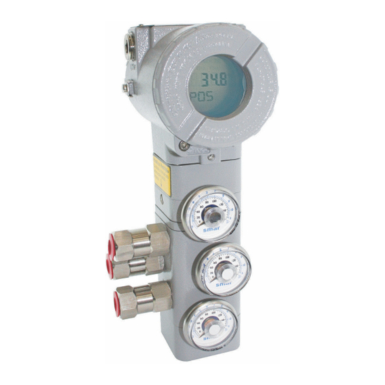
Figure 2.3 - Local Indicator Upon receiving power, the FY302 initializes the position indication on the display, by showing model FY302 and its software version (X.XX). The indication should be higher than ±19999 it will be displayed as two digits and an exponent. -
Page 24: Four Different Positions To The Lcd Display
FY302 – Operation, Maintenance and Instructions Manual Four Different Positions to the LCD Display As you can see below, there are four different positions for attaching the LCD display on the device in order to adequate it for a better view of its information. -
Page 25: Transducer Block
CONFIGURATION One of the many advantages of Fieldbus is that device configuration is independent of the configurator. A third party terminal or operator console may configure the FY302. Any particular configurator is therefore not addressed here. The FY302 contains one output transducer block, one resource block, one display transducer block and function blocks. -
Page 26: Fieldbus Positioner Transducer
FY302 – Operation, Maintenance and Instructions Manual Fieldbus Positioner Transducer Description The fieldbus positioner transducer receives the demanded valve position FINAL_VALUE from the AO block and uses it as a setpoint for a PID servo-positioning algorithm with adjustable gains SERVO_GAIN and SERVO_RESET. The transducer block also makes the corrected actual position sensor reading RETURN available to the AO block. - Page 27 Configuration Data Valid Initial/ Parameter Units Store Description Type Range Default Value The High and Low range limit values, the engineering unit code and the number of FINAL_VALUE_RANGE DS-68 100/0/% digits to the right of the decimal point to be used for Final Value. If the FINAL_VALUE is more positive than FINAL_VALUE_CUTTOF_ Float...
- Page 28 FY302 – Operation, Maintenance and Instructions Manual Data Valid Initial/ Parameter Units Store Description Type Range Default Value The percent measured value for the servo SERVO_PID_MV_PER DS-65 PID. module manufacturer identification MODULE_SN Unsigned32 number. ± INF SENSOR_PRESS _POL0 Float 31811.5 None The pressure sensor polynomial coefficient 0.
- Page 29 Configuration Data Valid Initial/ Parameter Units Store Description Type Range Default Value CAL_POINT_LO_FACTO Indicates the factory for lowest calibration Float point. SETUP Unsigned8 En/Dis Disable None Enable self-calibration. The position value used to correct a FEEDBACK _CAL Float calibration. CAL_CONTROL Unsigned8 En/Dis Disable...
- Page 30 FY302 – Operation, Maintenance and Instructions Manual Data Valid Initial/ Parameter Units Store Description Type Range Default Value It is the number of times the valve changes direction. The Reversal is incremented when ± INF REVERSAL Float None there is a changing in the direction and the movement exceeds the Reversal Deadband.
-
Page 31: Transducer Block Parameter Description
Configuration Transducer Block Parameter Description Parameter Description ST_REV Indicates the level of static data. TAG_DESC Description of Transducer Block. STRATEGY This parameter is not checked and processed by Transducer Block. ALERT_KEY Number of identification in the plant. MODE_BLK Indicates the operation mode of Transducer Block. BLOCK_ERR Indicates the status associated with hardware or software in the Transducer. - Page 32 FY302 – Operation, Maintenance and Instructions Manual Parameter Description POLYNOMIAL_HALL_VERSION The polynomial Hall version. USER_HALL_CAL_POINT_HI The highest calibrated point. USER_HALL_CAL_POINT_LO The lowest calibrated point. READ_HALL_CAL_POINT_HI The highest calibrated point for Hall sensor. READ_HALL_CAL_POINT_LO The lowest calibrated point for Hall sensor.
-
Page 33: Transducer Block Parameter Attributes
Configuration Parameter Description SENSOR_CAL_POINT_HI The highest calibrated point for the sensor pressure. SENSOR_CAL_POINT_LO The lowest calibrated point for the sensor pressure. SENSOR_PRESS_IN The reading of input sensor pressure SENSOR_PRESS_OUT1 The reading of out1 sensor pressure SENSOR_PRESS_OUT2 The reading of out2 sensor pressure SENSOR_PRESS_LO_LIM The maximum limit value for the input pressure SENSOR_PRESS_HI_LIM... - Page 34 FY302 – Operation, Maintenance and Instructions Manual Relative Object Parameter Mnemonic Data Type Store Size Access Default Value View Index Type COEFF_HALL_POL0 Simple Float 35331.0 COEFF_HALL_POL1 Simple Float 24999.0 COEFF_HALL_POL2 Simple Float COEFF_HALL_POL3 Simple Float COEFF_HALL_POL4 Simple Float COEFF_HALL_POL5 Simple...
-
Page 35: How To Configure A Transducer Block
This process is necessary to find the position values at which the valve is considered fully open or close. This operation can be done using the SYSCON or the Local Adjustment. The FY302 automatically finds the fully open and closed positions of a valve, but the user may also set a narrower range of operation should he like to. - Page 36 FY302 – Operation, Maintenance and Instructions Manual The SETUP operation is initiated writing This parameter "Enable" on its executes the parameter. Operation Called AUTO-SETUP. Figure 3.1 - Enabling the Auto-Setup Operation The "Disable" denotes that the SETUP operation was completed.
-
Page 37: Calibration
Configuration The setup progress can be followed by watching the parameters SETUP_PROGRESS. It goes from 0 to 100%. SETUP_PROGRESS goes from 0 to 100% Figure 3.3 - Setup Progress The setup process stuck sometimes because of wrong parameter configuration or a problem in the positioner assembly. -
Page 38: Position Trim
It is possible to calibrate the positioner by parameters CAL_POINT_LO and CAL_POINT_HI. Let’s take the lower value as an example: Write 0% in parameter CAL_POINT_LO. For FY302 it should be always 0%. Simply by writing in this parameter, the trim procedure is initialized. - Page 39 Figure 3.7 – Finishing Calibration Procedure FY2EM301.CDR For the upper value, for example: Write 100% in parameter CAL_POINT_HI. For FY302 it should be always 100%. Always keep in mind that, simply by writing in this parameter, the trim procedure is initialized. 3-15...
- Page 40 FY302 – Operation, Maintenance and Instructions Manual This parameter indicates where the positioner should be when the setpoint upper value is 100%. The desired value should be entered. Figure 3.8 - Calibrating High Range Value Point Check the position showed on the local indicator and if it is different of 100% write it in the parameter FEEDBACK_CAL.
- Page 41 Configuration The enable option indicates that the This parameter calibration process is ends the calibration being done. In order to procedure. finalize its procedure, the user should set it to disable. Figure 3.10 – End of Trim Procedure NOTE It is convenient to choose the unit to be used in parameter XD_SCALE of the Analog Output Block, considering that positioner limits shall be observed, it means 0% and 100%.
-
Page 42: Sensor Pressure
FY302 – Operation, Maintenance and Instructions Manual Sensor Pressure Some positioner FY302 has three sensors that work individually to monitor input and output pressures. Those pressure values can be used by a maintenance supervisory system, such as Asset View, for diagnosis procedure. -
Page 43: Flow Characterization
Configuration Flow Characterization The desired flow characteristics may be changed using this function. The options for applied flow characterization are: LINEAR, TABLE , EP25, EP33, EP50, QO25, QO33, QO50 The user can select the best flow The value of “False” characterization indicates that the Flow curve for each type... - Page 44 FY302 – Operation, Maintenance and Instructions Manual This parameter contains the These values are coordinates X. in percentage of Position Value before the Curve. Figure 3.14 - Configuring the Table for Flow Characterization - X points This parameter contains the These values are in coordinates Y.
-
Page 45: Temperature Calibration
Series 302 field devices from SMAR have the same methodology to handle with it. So, since the user has learned once, he is capable to handle all kind of field devices from SMAR. All function block and transducers defined according Foundation Fieldbus™ have a description of their features written on binary files, by the Device Description Language. -
Page 46: Definition Of Parameters And Values
FY302 – Operation, Maintenance and Instructions Manual Definition of Parameters and Values Block_Tag_Param This is tag of the block to which the parameter belongs. Use up to a maximum of 32 characters. Index_Relative This is the index related to the parameter to be actuated or viewed (0, 1, 2…). Refer to the Function Blocks Manual to know the desired indexes, or visualize them on the SYSCON opening the desired block. - Page 47 Configuration FY2EM309.CDR Figure 3.19 - Parameters for Local Adjustment Configuration Figure 3.20 - Parameters for Local Adjustment Configuration The option “update” should be selected in order to execute the This parameter updates update of local the local adjustment adjustment programmning tree programming tree.
-
Page 48: Calibrating Via Local Adjustment
FY302 – Operation, Maintenance and Instructions Manual Calibrating Via Local Adjustment The positioner has two holes for magnetic switches, located under the identification plate (See the section "Programming Using Local Adjustment"). These magnetic switches are activated by one magnetic tool. -
Page 49: Programming Using Local Adjustment
S and wait tool in orifice Z and during 5 seconds. wait until letters MD are displayed. Figure 3.22 - Step 1 - FY302 Insert the magnetic tool in orifice S Remove the once more and magnetic tool LOC ADJ should be from orifice S. - Page 50 FY302 – Operation, Maintenance and Instructions Manual In order to In order to start the decrement the LOPOS, simply insert lower position the magnetic tool in valve, place the orifice S as soon as magnetic tool in LOPOS is shown on orifice Z to shift the display.
- Page 51 Figure 3.28 - Step 7 - FY302 NOTE Every time the AUTO SETUP is used it is necessary to save it via SYSCON, and to write in the Backup-Restore parameter of the transducer block the sensor Data Backup option.
- Page 52 FY302 – Operation, Maintenance and Instructions Manual 3-28...
-
Page 53: Section 4 - Maintenance Procedures
Try spare parts in the positioner circuits. Pressure Output Connections Check up on air leaks. Air Supply Pressure Check the air supply pressure. The input pressure to FY302 shall be between 20 psi and 100 psi. NO RESPONSE TO INPUT SIGNAL Calibration Check the positioner calibration points. -
Page 54: Disassembly Procedure
FY302 – Operation, Maintenance and Instructions Manual NOTE The Factory Init should be tried as a last option to recover the equipment control when the equipment presents some problem related to the function blocks or the communication. This operation must only be carried out by authorized technical personnel and with the process offline, since the equipment will be configured with standard and factory data. -
Page 55: Reassembly Procedure
Maintenance Procedures Loosen the two screws (3) that anchors the indicator and the main circuit board. Gently pull out the indicator, and then the main board (5). Reassembly Procedure TRANSDUCER Mount the transducer to the housing turning clockwise until it stops. Then turn it counterclockwise until it faces the square of electronic housing to the square of transducer. - Page 56 FY302 – Operation, Maintenance and Instructions Manual Mount the o’rings again and screw the restriction in the positioner. The equipment can be supplied with air again. CHANGE OF THE FILTER ELEMENTS Change the positioner filter elements (See Figure 5.3 – Exploded View – Position 28) with a minimum stated period of 1 (one) year.
- Page 57 Operation, Maintenance and Instructions Manual (*) RETURNING MATERIALS Should it become necessary to return the positioner to SMAR, simply contact your local agent or SMAR office, informing the defective instrument’s serial number, written in identification plate, and return it to our factory in Sertãozinho/SP.
- Page 58 FY302 – Operation, Maintenance and Instructions Manual Figure 4.3 - Exploded View...
- Page 59 Maintenance Procedures SPARE PARTS LIST CATEGORY PARTS DESCRIPTION POSITION CÓDE (NOTE 4) HOUSING, Aluminum (NOTE 1) . 1/2 - 14 NPT 301-0340 . M20 x 1.5 301-0341 . PG 13.5 DIN 301-0342 HOUSING, 316 SS (NOTE 1) . 1/2 - 14 NPT 301-0343 .
- Page 60 FY302 – Operation, Maintenance and Instructions Manual SPARE PARTS LIST CATEGORY PARTS DESCRIPTION POSITION CÓDE (NOTE 4) ALUMINUM BLOCK SET 19,23,25,28,29,30,31 and 32 400-0651 316 STAINLESS STEEL BLOCK SET 19,23,25,28,29,30,31 and 32 400-0652 . Base & Block O-ring 400-0085 . Syntherized Bushing 400-0033 .
-
Page 61: Section 5 - Technical Characteristics
Section 5 TECHNICAL CHARACTERISTICS Functional Specifications Travel Linear Motion: 3 - 100 mm. Rotary Motion: 30 - 120° Rotation Angle. Input Signal Digital only. Fieldbus, 31.25 Kbits/s voltage mode with bus power. Output Output to actuator 0 -100% supply air pressure. Single or double-action. Power Supply Bus powered: 9-32 Vdc. -
Page 62: Performance Specifications
FY302 – Operation, Maintenance and Instructions Manual Performance Specifications Resolution ≤ 0.1% F.S. Repeatibility ≤ 0.1% F.S. Hysteresis ≤ 0.2% F.S. Consumption 0.25 Nm/h (0.15 SCFM) at 1.4 bar (20 psi) supply. 0.70 Nm/h (0.40 SCFM) at 5.6 bar (80 psi) supply. - Page 63 Technical Characteristics MODEL FIELDBUS VALVE POSITIONER FY302 CODE Local Indicator Without Indicator With Digital Indicator CODE Mounting Bracket** Without Bracket With Bracket CODE Electrical Connections ½ - 14 NPT M20 x 1.,5 Pg 13.5 DIN CODE Type of Actuator (Not Included) Rotary –...
- Page 64 FY302 – Operation, Maintenance and Instructions Manual BRACKET CODE Positioner Mounting Bracket Without Positioner Bracket Universal Rotary Universal Linear ( Yoke and Pillar) Linear – Yoke Type Linear – Pillar Type Others Specify CODE Magnet Mounting Bracket Without Magnet Mounting Bracket...
-
Page 65: Smar - General Terms Of Warranty
Smar manufactures its products with new parts and pieces, according to the industry good practices. Smar guarantees the products against defects of material, labor or performance during a period of 18 (eighteen) months, from the purchase date, as well as for spare parts used for repair. - Page 66 FY302 – Operation, Maintenance and Instructions Manual...
- Page 67 FY Positioner General Data Model: ( ) FY290 ( ) FY301 ( ) FY302 ( ) FY303 Hall Remote Sensor ? ( ) No ( ) Yes Pressure Sensor ? ( ) No ( ) Yes Action: ( ) Rotary...
- Page 68 FY302 – Operation, Maintenance and Instructions Manual...
- Page 69 APPENDIX MOUNTING BRACKET FOR POSITIONER – LINEAR STROKE VALVE MOUNTING INSTRUCTIONS 1 –Attach the magnet to the magnet bracket support before connect them to the valve stem. 2 - The stem nuts should be used to fasten the magnet bracket. 3 –...
- Page 70 Mounting Instructions 4 – Tighten the hex screw that join the two parts of the magnet bracket. It will avoid sliding of the two parts of the bracket during the fastening of the stem nuts. 5 – Tighten the stem nuts. 6 –...
- Page 71 BFY – MOUNTING BRACKET FOR POSITIONER FY 7 – Adjust the clamps according to the width of the yoke and tighten the bolts finger tight. 8 – Mount the positioner back plate. Tighten the nuts finger tight. 9 – Use the plate as a guidance to adjust the position of the positioner so that the back plate is about 1 mm apart from the magnet.
- Page 72 Mounting Instructions 10 – Fasten the nuts to fix the positioner bracket to the yoke. If the actuator is pillar type, fasten the U- clamp nuts. 11 – Mount the positioner to the plate and tighten the hex screws. You can take the back plate apart to facilitate the assembling.
- Page 73 BFY – MOUNTING BRACKET FOR POSITIONER FY 13 – Put the pressure equivalent to the half of the stem travel and adjust the height of the bracket assembly to have the arrows matching. 14 - Tighten the bolts to fasten the clamps to the yoke.
- Page 74 Mounting Instructions MOUNTING DETAILS FOR THE PILLAR TYPE ACTUATOR 15 - This is the mounting bracket using U- clamps to be mounted on pillar type actuators. 16 – After assembling the U-clamps, follow the steps 8 to 13.
- Page 75 ROTARY VALVE POSITIONER BRACKET MOUNTING INSTRUCTIONS Rotary Valve Positioner Bracket Parts. 1- Attach the clamps to the threaded orifices existent on the actuator. Do not tight them completely. The bolts are not supplied with the mounting bracket and they must be in accordance with size and thread of the actuator holes.
- Page 76 Mounting Instructions 3 – Fasten the hex screw. 4 – Attach the magnet to the NAMUR adapter. Do not fasten the bolts completely, allowing the magnet rotation. 5 – Mounting the positioner bracket through the threaded rods.
- Page 77 BFY – MOUNTING BRACKET FOR POSITIONER FY 6 – Use the centralizer gadget to get the bracket centralized with the magnet. 7 – Adjust the positioner bracket using the centralizer gadget and the nuts to get the height. 8 – Place the nut and washers. Do not fasten the nuts completely.
- Page 78 Mounting Instructions 9 – Tighten the clamp bolts to fasten them to the actuator. 10 – Fasten the positioner bracket bolts to the clamps fastening. 11 – Remove the centralizer gadget and fasten the positioner to the positioner bracket.
- Page 79 BFY – MOUNTING BRACKET FOR POSITIONER FY 12 – Put the pressure equivalent to the half of the stem and adjust the magnet position to have the arrows matching. 13 – Tighten the bolts to fasten the magnet to the magnet bracket.
Need help?
Do you have a question about the FY302 and is the answer not in the manual?
Questions and answers