Advertisement
Quick Links
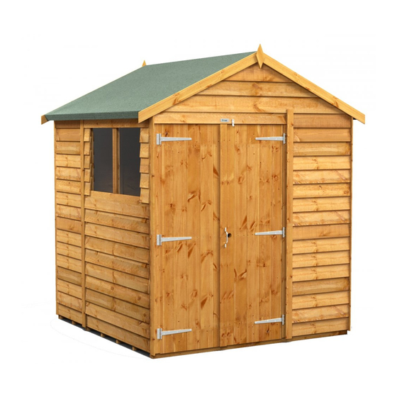
Thank you for purchasing
a 6x6 Apex Storage Shed.
Please take the time to identify
all the parts prior to assembly.
Safety Points and Other Considerations
Our products are built for use based on
proper installation and normal residential
use, on level ground. Please follow the
instruction manual when building your
shed and retain the manual for future
maintenance purposes.
Some of the safety and usage measures you may wish to consider include:
-snow load ratings vary by geographical location. If heavy or wet snowfall occurs, it is advisable to sweep the
snow off the roof(s).
-if the product is elevated, any structural and building code requirements are solely the customer's
responsibility, and should be abided by.
-in high or gusty wind conditions it is advisable to keep the structure securely grounded.
-have a regular maintenance plan to ensure screws, doors, windows and parts are tight.
Customer agrees to hold Outdoor Living Manufacturing Ltd. and any Authorized Dealers
free of any liability for improper installation, maintenance and repair.
In the event of a missing or broken piece, simply call the Outdoor Living Today
Customer Support Line @ 1-888-658-1658 within 30 days of the delivery of your
purchase. It is our commitment to you to courier replacement parts, free of charge,
within 10 business days of this notification. Replacement parts will not be
provided free of charge after the 30 day grace period.
1-888-658-1658
6x6 Apex Storage Shed
www.outdoorlivingtoday.com
Page 1
Assembly Manual
Version #4
Jan 24th, 2018
sales@outdoorlivingtoday.com
Advertisement

Related Manuals for OLT 6x6 Apex


Summary of Contents for OLT 6x6 Apex
- Page 1 Assembly Manual Version #4 Jan 24th, 2018 Thank you for purchasing a 6x6 Apex Storage Shed. Please take the time to identify all the parts prior to assembly. Safety Points and Other Considerations Our products are built for use based on proper installation and normal residential use, on level ground.
-
Page 2: Parts List
Thank you for purchasing a 6x6 Apex Storage Shed Please take the time to identify all the parts prior to assembly. Parts List: 1. Floor Section 2 - 35” x 75” - Floor Frames - 1A 4 - 1 1/2” x 3 1/2” x 72” - Floor Joists - 1B 3 - 1 1/2”... - Page 3 6 x 6 Apex HARDWARE PACKAGE Screws and Nails (actual size) 1 1/2” (F) - 250 Pcs. Finishing Nail (A) - 1 Pc. 1 1/4” (N) - 30 Pcs. Shingle Nail Square Drive Bit 2 1/2” (B) - 164 Pcs. Simpson Strong Tie (G) - 8 Pcs.
- Page 4 What Can I Do Before My Shed Arrives? Before starting your project become familiar with this assembly manual and determine if you can complete the project yourself or will require a professional contractor. Please note that certain counties and municipalities require building permits prior to installation. We recommend to all consumers that they check with their local county/municipality for these specifics prior to purchasing any of our products since this is your sole responsibility.
-
Page 5: Floor Section
A. Floor Section Exploded view of all parts necessary to complete Floor Section. Identify all parts prior to starting. Note, Floor Footprint is 70” wide x 75” deep. Plywood Flooring - 2 pcs. (Part 1D) Floor Joists - 4 pcs. (Part 1B) Floor Frames 2 pcs. - Page 6 You can find the Square Drive Bit (Part A) for the screws in with the Hardware Kit Bag. When correctly positioned, attach each joist with 4 - 2 1/2” screws (Part B) - 2 per end. Complete Joist attachments for 2nd Floor Frame. Lay out both completed Floor Frames as illustrated.
- Page 7 Attach Floor Runners 3 @ 1 1/2” x 3 1/2” x 70” Make sure runners are flush with outside and (Part 1C) to completed floor frames. There are 3 front and rear floor framing but not overhanging. floor runners per 70” side. Use 8 - 2 1/2” Screws (Part B) per runner.
- Page 8 Completed Floor With Plywood positioned correctly on floor framing, attach using 16 - 1 1/4” screws (Part C) 75” plywood per sheet. pushed together at seam 2. Wall Section Exploded view of all parts necessary to complete the Wall Section. Identify all parts prior to starting. Gable Walls - 2 pcs.
- Page 9 Lay out all the wall panels. Make sure to position panels right side up so water is directed away from and not into shed. Note, to determine correct alignment, the attached Bottom Wall Plate of wall panel will be sitting on floor. I piece of spare Bevel Wall Siding - 3/4”...
- Page 10 Optional - Caulking seams will help prevent moisture from entering at seam. Caulking not included in kit. Position side wall into place on plywood floor. Butt both vertical wall frames of side and rear walls together tight and attach with 3 - 2 1/2” screws (Part B).
- Page 11 Align vertical wall frames of both side wall panels together and attach with 3 - 2 1/2” screws (Part B). Locate and position the 2nd rear wall panel into place. Wall panel framing aligned flush with floor framing Align wall panel framing as per Step 18. The wall panel framing with sit flush with floor framing as shown above.
- Page 12 When aligning Jambs and Header in Steps 21-23, do a dry run first to confirm spacing. Tack jambs with only a few screws initially. Jambs should be 64” apartment when measure inside to inside. 1/2” overhang on inside of wall framing Locate Door Jambs - 2 @ 2 1/2”...
- Page 13 On ends, screwing on slight angle provides more strength. Top Plate aligned flush with inside of wall framing Position one Side Top Plate (angle cut on both ends) - 3/4” x 2 1/2” x 75” (Part 2E) on top wall framing. Top plate should be evenly spaced from front to back and aligned flush with the inside of top wall framing.
- Page 14 Complete remaining Side and Rear Top Plate attachments as per Steps 24-25. Attach front Front Triangular Corner Brackets - 1 1/2” x 5 1/2” x 5 1/2” (Part 2G) to header and wall frame with 2 - 2 1/2” screws (Part B) per piece. Attach walls to floor now.
- Page 15 Gable Wall Straight Edge Gable Flashing Gable Frame Locate and place Gable Wall (Part 2H) so gable framing sits flush with the inside of the top plate. Center from front to rear using a Straight Edge to confirm angle of gable frame and Top Plate line up. Adjust gable accordingly.
- Page 16 3. Rafter and Roof Section Exploded view of all parts necessary to complete the Roof Section. Identify all parts prior to starting. Roof Ridge Caps - 12 pcs. Roof Facia Cleats (Part 3I) 42 pcs. (Part 3F) Left Roof Panels - 2 pcs.
- Page 17 Attach Ridge Board to ends of both outside rafters with 2 - 2” Ridge Board screws (Part E) per end. Drill 1/8” pilot holes in Ridge Board to prevent splitting. Measure and position interior Rafters as illustrated below. Double up center rafters and screw together with 2 - 2 1/2”...
- Page 18 Starting at the rear and with a helper, flip a completed rafter section over and lift up and place rafter section on gable wall framing. Soffit Rafter should rest on gable framing Gable Notch Slide rafter section up on gable framing until bottom of ridge board slips into gable notch.
- Page 19 Screw Ridge Boards together with 1 1/4” screws Gable Notch. With ridge board locked into gable notch, align ridge boards so they are flush together and secure them with 8 - 1 1/4” screws (Part C). Important - if there is a gap between Ridge Boards, try pushing rear wall and Door Header closer together from outside.
- Page 20 The Roof Gusset 1- 3/4” x 3 1/2” x 48” (Part 3D) is positioned on center rafter. Use level to square gusset and attach to rafter with 4 - 1 1/4” screws (Part C). Pilot hole Gusset to prevent splitting. If we required, have a helper(s) push at the front and at the rear near the top of the walls from the outside of shed until inside to inside measurement between the top plates is 70”...
- Page 21 1 screw at top into ridge board. Screw panel down at top only with 1 - 2 1/2” screws (Part B). Place second roof panel on rafters. Align and attach. Roof will be completely secured in later Steps. Do not attach further until Step 49. Position and attach front side roof panels as per Steps 45-47.
- Page 22 Slide in next long filler shingle and attach with 2 - 2 1/2” screws (Part B) as per Step 49. Slide in remaining Filler Shingles (Part 3H & 3I) and attach in order. The top Filler Shingle (Part 3I) is shorter. Important: Butt (thick) end of Ridge Cap will be facing towards the...
-
Page 23: Miscellaneous Section
Attach 2 Simpson Strong Ties (Part G) per outside rafter with 4 - 1 1/4” screws (Part C). Total of 8 ties. Further secure roof by attaching rafters to 4 - 90 degree roof with 3 - 2 1/2” screws (Part B) per rafter. Simpson Ties / Gable 3 - 2 1/2”... - Page 24 Note: All Trim, Facia and Bottom Skirting pieces will be positioned rough face out when installed. Flush with inside of Door Jamb Locate both 3/4” x 4 3/8” x 79” Door Trims (Part 4A). Position a Trim so it covers the Door Jambs and is flush with the inside of it.
- Page 25 Align trim tight under- neath Soffit and Rafter Attach Side Rear Wide Trim - 1/2” x 4 1/2” x 77 1/2” (Part 4E) and Narrow Trims (Rear Wall) 1/2” x 2 1/2” x 79” (Part 4F) with 6 - 1 1/2” Finishing Nails (Part F) per piece. Narrow Wide Side Front Wide Trim (4G)
- Page 26 Detail Plate Attach Horizontal Gable Detail Plate Attach Narrow Trim (Side Wall) - 1/2” x 2 1/2” (Part 4J) with 4 - 1 1/2” Finishing Nails x 77 1/2” (Part 4I) with 8 - 1 1/2” Finishing (Part F). Nails (Part F). Side Facia Attach Side Facia 3/4”...
- Page 27 Note, illustration of Hinge may not be accurate. The # of screw holes in the hinge may vary from three to four depending on model. 3/4” screws Important- Drill Pilot Holes to prevent splitting. 2“ Screws Locate Left and Right Doors (Parts 4N & 4O). Lay with framing down. Attach 3 Door Tee Hinges (Part H) using Black Headed 3/4”...
- Page 28 Position and attach Right Door (4O) as per Steps 68-69. Door position may need slight adjusting to open and close correctly. When satisfied, complete all 2” Black Headed Screws (Part I) Note, Do not over tighten hinge screws when using screw gun. Above Door Trim Attach Above Door Trim - 1/2”...
- Page 29 Threshold Attach Door Threshold - 3/4” x 2 1/2” x 62 1/2” (Part 4S) with 4 - 2” screws (Part E). Door Flange Attach Interior Door Flange - 1/2” x 2 1/2” x 71” (Part 4T). Position on inside door frame (left door from outside) using 6 - 2”...
- Page 30 Position Door Stops 1/2” x 2 1/2” x 71” (Part 4U) in each corner screwing into door framing using 6 - 2” screws Door Stop (Part E). Before attaching stop to door, check positioning to confirm Door Stop does not bind and adjust accordingly.
- Page 31 Congratulations on assembling your 6x6 Apex Storage Shed! Note; Our Sheds are shipped as an unfinished product. If exposed to the elements, the western red cedar lumber will weather to a silvery-gray color. If you prefer to keep the cedar lumber looking closer to the original color, we suggest that you treat the wood with a good oil base wood stain.
Need help?
Do you have a question about the 6x6 Apex and is the answer not in the manual?
Questions and answers