Table of Contents
Advertisement
Quick Links
USER'S MANUAL
For
VlA VX900 Express Chipset
Based Motherboard
NO. G03-MVBVX9GSM-F
Rev: 1.0
Release date: November, 2010
Trademark:
* Specifications and Information contained in this documentation are furnished for information use only, and are
subject to change at any time without notice, and should not be construed as a commitment by manufacturer.
Advertisement
Table of Contents

Related Manuals for VIA Technologies VX900


Summary of Contents for VIA Technologies VX900
- Page 1 USER'S MANUAL VlA VX900 Express Chipset Based Motherboard NO. G03-MVBVX9GSM-F Rev: 1.0 Release date: November, 2010 Trademark: * Specifications and Information contained in this documentation are furnished for information use only, and are subject to change at any time without notice, and should not be construed as a commitment by manufacturer.
- Page 2 Environmental Safety Instruction Avoid the dusty, humidity and temperature extremes. Do not place the product in any area where it may become wet. 0 to 40 centigrade is the suitable temperature. (The figure comes from the request of the main chipset) Generally speaking, dramatic changes in temperature may lead to contact malfunction and crackles due to constant thermal expansion and contraction from the welding spots’...
-
Page 3: Table Of Contents
TABLE OF CONTENT CHAPTER 1 INTRODUCTION OF VIA VX900 MOTHERBOARDS FEATURES OF MOTHERBOARD..............1 1-1.1 SPECIAL FEATURES OF MOTHERBOARD .........2 ITEM CHECKLIST..................2 SPECIFICATION ...................3 LAYOUT DIAGRAM ..................4 CHAPTER 2 HARDWARE INSTALLATION MEMORY MODULE INSTALLATION............5 EXPANSION SLOTS..................6 CHAPTER 3 CONNCTORS, HEADERS & JUMPERS SETTING CONNECTORS .....................6... -
Page 4: Chapter 1 Introduction Of Via Vx900 Motherboards Features Of Motherboard
Introduction of VIA VX900 Motherboards Features of Motherboard The VIA VX900 Express chip based motherboard series are based on VIA VX900 Express chipset technology which supports the embedded VIA Nano™ 2007L Series The VIA VX900 chipset based motherboard series comes with an integrated DDRIII... -
Page 5: Special Features Of Motherboard
20 degrees. Life of product of motherboard with solid capacitors declines only 10% of those without solid capacitors as well under same conditions. Item Checklist VIA VX900 Chipset based motherboard DVD for motherboard utilities User’s Manual SATA Cable(s) -
Page 6: Specification
Support dual channel function 1pcs PCI-Express2.0 x16by8 lane slot Expansion Slots 1pcs 32-bit PCI slot The VIA VX900 chipset supports two internal Serial ATA Serial ATA2 ports for two SATA devices providing 3.0 Gb/sec data transfer rate. Integrated PCI-E LAN chip... -
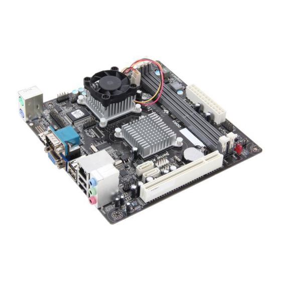
Page 7: Layout Diagram
ATX 12V Power Connector USB Connector VIA Nano™ L2007 CPU DDRIII Slot x 2 VGA Connector CPU FAN1 HDMI Connector VIA VX900 Chipset USB Connector LAN Chip RJ-45 Over USB Connector SYSFAN1 Audio Connector COM Header Front Panel Audio Header... -
Page 8: Chapter 2 Hardware Installation
Chapter 2 Hardware Installation WARNING! Turn off your power when adding or removing expansion cards or other system components. Failure to do so may cause severe damage to both your motherboard and expansion cards. Memory Module Installation This motherboard provides two 240-pin DDR III DUAL INLINE MEMORY MODULES (DIMM) socket for DDR III memory expansion available to maximum memory volume of 8 GB DDRIII SDRAM. -
Page 9: Expansion Slots
The two plastic clips will automatically close if the memory module is fitted in a proper way. 2-2 Expansion Slots The VIA VX900 Express chipset based motherboard series offer one PCI-Express2.0 x16 graphics slot and one 32-bit PCI slot guarantee the rich connectivity for the I/O of peripherals. - Page 10 ROW ROW ROW1 ROW2 ROW ROW 3.3V 3.3V 3.3V -12V Soft Power On Power OK +5V (for Soft Logic) +12V +12V 24-Pin 20-Pin ** If you are using a 20-pin power plug, please refer to Figure1 for power supply connection. Power plug form power supply and power connectors from motherboard both adopt key design to avoid mistake installation.
-
Page 11: Headers
(7) Serial-ATA2 Port connectors: SATAII-1~SATAII-4 These connectors support the provided Serial ATA hard disk cable to connect the motherboard and serial ATA2 hard disk drives. SATA1 SATA2 Serial ATAII Connector (8) D-Sub 15-pin Connector: VGA VGA is the 15-pin D-Subminiature female connector; it is for the display devices, such as the CRT monitor, LCD monitor and so on. - Page 12 (3) Speaker connector: SPEAK This 4-pin connector connects to the case-mounted speaker. See the figure below. (4) Power LED: PWR LED The Power LED is light on while the system power is on. Connect the Power LED from the system case to this pin. (5) IDE Activity LED: HD LED This connector connects to the hard disk activity indicator light on the case.
- Page 13 (9) S erial COM Port header: COM1 COM1 is a 9-pin block header. Pin1 Serial COM Port 9-pin Block (10) SPDIF Out header: HDMI_SPDIF1 The SPDIF output is capable of providing digital audio to external speakers or compressed AC3 data to an external Dolby digital decoder. Use this feature only when your stereo system has digital input function.
-
Page 14: Jumper Setting
3-3 Jumper Setting (1) CMOS RAM Clear (2-pin): JBAT A battery must be used to retain the motherboard configuration in CMOS RAM, short 1-2 pins of JBAT to clear the CMOS data. To clear the CMOS, follow the procedure below: Turn off the system and unplug the AC power Remove ATX power cable from ATX power connector Locate JBAT and short pins 1-2 for a few seconds, if shorted with the jump cap,... -
Page 15: Chapter 4 Useful Help
Chapter 4 Useful Help 4-1 How to Update BIOS Step1. Prepare a bootable disk. (You may make one by click START click RUN type SYS A: click OK) Step2. Download upgrade tools and the latest BIOS files of the motherboard from official website and then make a copy of it to your bootable floppy disk after decompressing these files Step3.
Need help?
Do you have a question about the VX900 and is the answer not in the manual?
Questions and answers