
Related Manuals for SystemAir AW 200 EC


Summary of Contents for SystemAir AW 200 EC
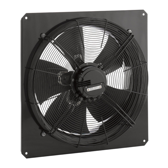
- Page 1 Axial Fans AW, AR Installation and Operating Instructions Document in original language | · 004...
- Page 2 © Copyright Systemair AB All rights reserved E&OE Systemair AB reserves the rights to alter their products without notice. This also applies to products already ordered, as long as it does not affect the previously agreed specifications. | 004...
-
Page 3: Table Of Contents
Contents General information .........1 Warning symbols ........1 1.1.1 Instruction symbols.....1 Important safety information ......1 Personnel ..........1 Personal protective equipment....2 5 rules of electrical safety ......2 Warranty ............2 Delivery, transport, storage .......2 Description ............3 Intended use .........3 Incorrect use ........3 Technical data ........3 Name plate and type key ........4 Installation.............5 Installation positions .......6... -
Page 5: General Information
General information | General information Warning symbols Danger Caution Hazard with a low risk Direct hazard Failure to comply with this warning may lead to Failure to comply with this warning will lead moderate injuries. directly to death or to serious injury. Important Warning Hazard with risk of damage to objects... -
Page 6: Personal Protective Equipment
Further prerequisites are a completed maintenance plan with no gaps and a commissioning re- port. Systemair will require these in the case of a warranty claim. The commissioning report is a component of this document. The maintenance plan must be created by the operator, see section Maintenance. -
Page 7: Description
♦ Check that the motor bearing functions properly before installation. Description Intended use • Systemair axial fans of the series AR and AW are exclusively designed as a built-in device for conveying air according to its technical data. Incorrect use Incorrect use refers mainly to using the fan in another way to that described. -
Page 8: Name Plate And Type Key
| Name plate and type key Name plate and type key Type designation Voltage/frequency/current/ power/fan impeller speed Capacity/capacitor voltage* Moisture protection* Insulation class Article no. Certifications * Not available with every device Table 2 Type key Large motor version Normal motor version Motor type Electronically commutated/1 phased or 3 phased 2 poled/controllable by frequency converter/1 phased... -
Page 9: Installation
Installation | Installation Safety information General safety information General safety information ♦ Observe 2 Important safety information, page 1 ♦ Use installation material with fire resistance classes that meet temperature requirements. ♦ Provide contact and intake protection and ensure safety distances according to DIN EN ISO13857 and DIN 24167-1. ♦... -
Page 10: Installation Positions
| Installation Installation positions The installation is possible in any mounting position. AW 200 EC AW 250 EC AW 300 EC AW 350 EC AW 400 EC sileo sileo sileo sileo sileo (#35854) (#35855) (#35857) (#35859) (#35860) AW 300E2 AR 300E2... -
Page 11: Electrical Connection
Hz, in combination with electronic devices such as EC motors, frequency converters or uninterruptible power supplies (UPS). Table 3 Description of electrical connections of the following fans: AW 200 EC sileo (#35854), AW 250 EC sileo (#35855), AW 300 EC sileo (#35857), AW 350 EC sileo (#35859)AW 400 EC sileo (#35860), AW 450 EC sileo... - Page 12 | Electrical connection Client side Max. speed Adjustable speed 10V –> n = max 1V –> n = min <1V –> 0 Adjustable speed through PWM Adjustable speed through potentiometer 1...10 KHz 100 % PWM –> n = max 10 % PWM –> n = min <...
- Page 13 Electrical connection | Table 4 Description of electrical connections of the following fans: AW 500 EC sileo (#35865), AW 500D EC (#35866), AW 560D EC sileo (#35867) Wire Function/assignment Connection Protective conductor Power supply, see name plate for voltage range Power supply, see name plate for voltage range 1, 2* N, L*...
- Page 14 | Electrical connection Table 5 Description of electrical connections of the following fans: AW 630D EC sileo (#35872), AW 710D-L EC sileo (#35876), AW 800D EC sileo (#35879), AW 1000D EC sileo (#35899) Wire Function/assignment Connection Protective conductor Power supply, see name plate for voltage range Status relais, open for failure Status relais, changeover contact, common connection (2 A, max.
-
Page 15: Electrical Connection Accessories
Electrical connection | Electrical connection accessories The following wiring diagrams show the electrical connections between accessories and motor/frequency fans (with EC motor) or frequency converters (e.g. FRQ, FRQS, FXDM) which can be converter controlled with a 0–10V signal. If you are not sure if your fan is equipped with an EC- motor please see chapter 6 Name plate and type key, page 4. -
Page 16: Commissioning
| Commissioning Caution Damage as a result of incorrect commissioning of the frequency converter. ♦ Install the fan and frequency converter as near as possible to one another. ♦ Use shielded cables. ♦ All components (fan, frequency converter and motor) must be grounded. ♦... -
Page 17: 11.1 Troubleshooting
Thermal contacts/ resistors have Check the cooling impeller (if used), measure the motor triggered Motor overheated winding (if possible) / contact Systemair. Capacitor (if used) not or not Connect the capacitor correctly. correctly connected. Contact Systemair Motor blocked... -
Page 18: 11.2 Maintenance
Check the flexible connectors for damage. See normal operating conditions Spare parts ♦ Use original spare parts from Systemair only. ♦ When ordering spare parts, please specify the serial number of the fan. This can be found on the name plate. | 004... -
Page 19: Cleaning
Cleaning | Cleaning Safety information ♦ Observe 2 Important safety information, page 1 Procedure Keeping the fan clean extends its service life. • Install a filter monitor. • Change the filters of the ventilation system. • Do not use steel brushes or sharp-edged objects. •... - Page 20 | Commissioning Report □ □ Frequency converter □ □ Sinus filter □ □ Shielded cables Motor protection □ □ Motor protection switch or motor protection relay □ □ PTC resistor Resistance value [Ω]: □ □ Thermal contact □ □ Electrical motor protection Others: Functional check □...
- Page 21 | 004...
- Page 22 Systemair GmbH Seehöfer Str. 45 97944 Boxberg Germany Tel.: +49 (0)7930/9272-0 Fax: +49 (0)7930/9273-92 info@systemair.de www.systemair.de...
Need help?
Do you have a question about the AW 200 EC and is the answer not in the manual?
Questions and answers