Table of Contents
Advertisement
Quick Links
0
MODELS: SRB40CRE (-2,-4, -9) with PILOT IGNITION
INSTALLATION
AND OPERATION
INSTRUCTIONS
OWNER/INSTALLER: For your safety this manual must be carefully read before installing, operating or
servicing this brooder. This brooder is intended for use with either Natural Gas or Propane Gas and must be
installed in accordance with the relevant provisions of any National Gas Safety (Installation and Use)
Regulations. Due account should also be taken of any obligations arising from any National Health and
Safety at Work Regulations, National and Local Building Regulations and National Electrical Wiring
Regulations. The appliance must be installed, and where necessary, converted for use on other gases, by a
qualified installer.
▲WARNING: Improper installation, adjustment, alteration, service or maintenance can cause injury, property
damage or death. Refer to this manual. For assistance or additional information, consult a qualified
installer, service agency or the gas supplier.
INSPECT all combustion air openings into the building and, if necessary, clear as they become blocked by
litter, dust, feathers or other matter.
INSPECT and clean the brooder filters on a regular basis to allow proper brooder operation.
FOR YOUR SAFETY: EXHAUST FANS MUST be operating on an appropriate cycle when brooders are operating
to avoid a high concentration of carbon monoxide. When used without fresh air, this brooder may give off
carbon monoxide, an odourless and poisonous gas. CARBON MONOXIDE POISONING MAY LEAD TO DEATH.
Early signs of carbon monoxide poisoning resemble the flu with headaches, dizziness and nausea. If you
experience these signs, GET FRESH AIR IMMEDIATELY! Have the brooders serviced as soon as possible and
check the ventilation in the house.
These brooders are designed for agricultural applications and may operate with the use of either Natural Gas
or Liquid Propane (LP) Gas. Check the brooder's nameplate to determine the correct gas type before
proceeding with installation.
IF YOU SMELL GAS:
! DO NOT try to light any appliance.
! DO NOT touch any electrical switch; do not use any
telephone in your building.
! IMMEDIATELY call your gas supplier from a neighbour's
telephone. Follow the gas supplier's instructions. If you
cannot reach your gas supplier, call the fire department.
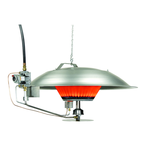
RADIANT GAS BROODER
FOR YOUR SAFETY
DO NOT store or use petroleum or
other flammable vapours and liquids
in the vicinity of this or any other
appliance.
SAVE THIS MANUAL
FOR FUTURE REFERENCE.
Form 43539178
Oct 2019
Advertisement
Table of Contents

Related Manuals for Space-Ray SRB40CRE-N2


Summary of Contents for Space-Ray SRB40CRE-N2
- Page 1 RADIANT GAS BROODER MODELS: SRB40CRE (-2,-4, -9) with PILOT IGNITION INSTALLATION AND OPERATION INSTRUCTIONS OWNER/INSTALLER: For your safety this manual must be carefully read before installing, operating or servicing this brooder. This brooder is intended for use with either Natural Gas or Propane Gas and must be installed in accordance with the relevant provisions of any National Gas Safety (Installation and Use) Regulations.
-
Page 2: Table Of Contents
TABLE OF CONTENTS Section Description Page GENERAL INFORMATION .................... 1 BROODER SPECIFICATIONS ..................2 BROODER CONTROL OPTIONS .................. 2 BROODER ASSEMBLY ....................3 MINIMUM CLEARANCES TO COMBUSTIBLES ............6 BROODER INSTALLATION ................... 7 GAS CONNECTIONS ..................... 8 ELECTRICAL CONNECTIONS ..................13 COMMISSIONING ...................... -
Page 3: Brooder Specifications
BROODER SPECIFICATIONS Table 1. Space-Ray SRB40CRE MODEL Types N2 / L2 / N4 / G4 / L4 / N9 / L9 Heat Input 11.72kW Appliance Type Appliance II2H3P, II2H3B/P, II2E3P, II2Er3P, II2Er3B/P, II2L3P, II2L3B/P, II2ELL3P, Cat.(II) II2ELL3B/P, II2E(R)B3P Model suffix Appliance Cat.(I) -
Page 4: Brooder Assembly
BROODER ASSEMBLY 1. Make sure that all components are present before assembling the brooder: Qty. Description Qty. Description Control Arm Emitter Assembly Safety Pan Low Profile Hanging Bracket (includes eyebolt) Canopy Fastener Kit Burner Base Manifold Support Bracket & Clamp The Fastener Kit contains all the nuts, screws and washers required for brooder assembly. - Page 5 5. Flip the Emitter/Canopy Assembly over. Secure the Burner Base to the Burner Cap (which is attached to the Emitter Assembly) and secure it in place using three (3) #10-24 hex locknuts from the Fastener Kit. NOTE: Make sure that the two (2) holes located on the Burner Base are facing the two (2) holes in the edge of the Canopy.
- Page 6 9. Insert the Orifice Fitting into the burner base as shown in Figure 3a. Rotate the swivel clamp until it locks into the groove of the orifice fitting. 10. Tighten the screws and nuts holding the Manifold Support Bracket Assembly installed earlier above in Figure 3.
-
Page 7: Minimum Clearances To Combustibles
▲WARNING: ONCE THE BROODER IS ASSEMBLED AND BEFORE IT IS FIRST FIRED, YOU MUST CHECK FOR GAS LEAKS! USE A SOAP AND WATER SOLUTION AND APPLY AT ORIFICE FITTING, PILOT ASSEMBLY, AND FIELD CONNECTION AT THE GAS VALVE. COMPLETE ASSEMBLY FIGURE 4 MINIMUM CLEARANCES TO COMBUSTIBLES Minimum clearances to combustible materials shall be measured from the outer surface of the... -
Page 8: Brooder Installation
BROODER INSTALLATION 1. Locate brooders approximately 8m to 12m apart, in a row, as needed for bird comfort and building heat loss. If more than one row is desired, stagger rows for best heat distribution. FIGURE 5a 2. Suspend the brooder at the desired height above the floor (litter) level, normally 1520mm to 1830mm. -
Page 9: Gas Connections
GAS CONNECTIONS 1. Gas piping for the house must be sized to be capable of satisfying the entire demands of the house should all equipment be operating at the same time. Please use Table 1 as a guide for the sizing of piping for the house. An example using this table is shown. 2. - Page 10 8. Space-Ray recommends that the hose is installed with a spring (item 4) shown below to keep the hose vertical directly above the canopy. If the brooder is raised and lowered during operation it is the installer’s responsibility to ensure that the hose cannot come into contact with the canopy.
- Page 11 INSTRUCTIONS FOR TESTING FOR GAS LEAKS AND PROPER GAS PRESSURE ▲ WA R NI N G: D O N OT O M IT T HE SE TE ST S ! TESTING THE INSTALLATION FOR GAS LEAKS: 1. Inspect all connections and appliance valves to be sure connections are wrench-tight and that all appliance valves are closed, including the pilot valves.
- Page 12 CHECK GAS OUTLET (MANIFOLD) PRESSURE: 1. Be sure that the valve is in the “OFF” position before removing the pressure tap plug at the valve. With the main burner operating, check the manifold pressure using a lower-pressure test set connected to the Outlet Pressure Tap. (Refer to Figure 6 or 6a for each control valve type.) The controls have combination valves with built-in appliance regulators.
- Page 13 To perform the lock-up and leakage test, follow these steps: 1. With the LP tank valve fully open, shut off all appliance valves so there is no demand for gas. This includes shutting off all pilots. 2. A slight rise in pressure will occur under these conditions. This rise should be no more than 120% of the delivery pressure.
-
Page 14: Electrical Connections
TABLE 1 . -- LP Gas Pipe Sizing between Single or Second Stage Regulator and Brooders. Tubing Size, O.D. Type L Nominal Pipe Size, I.D. Schedule 40 3/8” 1/2” 5/8” 3/4” 7/8” 1-1/8” 1/2” 3/4” 1” 1-1/4” 1-1/2” 2” 3” 4”... - Page 15 No. of Brooders x 12.0VA x 1.25 Safety Factor = Transformer Size No. Brooders Minimum Transformer VA 4. The wire to the #2 type brooders MUST be a minimum 2.5mm 5. Failure to connect the #2 type brooders to the minimum power supply recommended or to use a cable less than the minimum size specified will result in the brooder not functioning properly.
-
Page 16: 9A) Commissioning
COMMISSIONING It is essential that all new pipework installations are purged and tested for sounding using a suitable leak detection fluid prior to attempting to ignite any appliance. This work should be carried out in accordance with National or Local Regulations. DO NOT TEST FOR SOUNDNESS BY USE OF NAKED FLAMES. -
Page 17: Ventilation
VENTILATION FOR YOUR SAFETY: Exhaust fans must be operating on an appropriate cycle when heating the building to avoid high concentrations of carbon monoxide and water vapour. The temptation, particularly during the winter months, is to close up the poultry house to conserve heat and save money. - Page 18 Ventilation by natural air change. Gas fired radiant heaters may be operated without any special exhaust system if the exhaust gases are discharged to the outside atmosphere by a sufficient natural air change in the installation room. Furthermore, no provision for thermal or mechanical ventilation is required in the following particular cases: Buildings with natural air change greater than 1.5 volumes per hour ii).
-
Page 19: Mainenance, Servicing And Conversion Instructions
SERVICING and MAINTENANCE CAUTION: Turn the gas and electrical supply OFF and allow the brooder to cool down for 20 minutes before attempting any maintenance. MAINTENANCE: Maintenance is defined as work that a non-gas competent person may carry out on the appliance. This work must not involve the use of tools to maintain/access the gas and electric components on the appliance. - Page 20 SERVICING: A qualified person must service the appliance. Servicing is defined as work that requires the use of tools or the person to access/remove components along the control arm assembly. The brooder must be serviced annually as a minimum, or more frequently as circumstances/conditions dictate. To keep your brooder in good operating condition, we recommend that after each crop you blow any dust and dirt from the brooder with compressed air.
- Page 21 3. Apply pipe thread sealant Part No. 05001010 PIPETITE-STIK #11175 (resistant to LP Gas) to the threads of the orifice and replace it into the orifice fitting. Avoid over tightening the orifice as this will make future removal very difficult. FIGURE 10 4.
- Page 22 FIGURE 13 FIGURE 12 9. Remove the pilot burner orifice and clean the orifice hole with a drill bit the same size as the orifice or by soaking the orifice in acetone liquid cleaner. Dry the orifice by blowing compressed air through it. NOTE: Care must be taken not to ream the orifice hole to a larger diameter as this will result in over firing the burner and potentially causing damage to the emitter.
- Page 23 GAS CONVERSION INSTRUCTIONS. Conversion from one gas category to another MUST be carried out by a qualified person. 1. Turn off electric (if equipped) and gas supply to the brooder. 2. Release the main burner orifice fitting and pan from the burner by turning the swivel clamp.
- Page 24 5. Insert orifice holder back into burner base and securely push the swivel clamp into place locking the orifice holder. 6. Remove the windshield and housing tab, unscrew the pilot burner orifice from the orifice fitting. 7. Apply a small amount of thread sealant to the threads of the replacement orifice making sure not to get any into the orifice or holder.
- Page 25 COMBUSTION AIR RING ASSEMBLY INSTRUCTIONS - (NATURAL GAS MODELS ONLY) Models operating on Natural Gas must have an additional combustion air ring and a burner pan having an air inlet hole. This is required for proper combustion of the gas and air mix. Assemble these items as indicated below in the separate instructions.
-
Page 26: Troubleshooting
TROUBLESHOOTING TROUBLE POSSIBLE CAUSE SOLUTIONS ♦ There is air in the gas line. ♦ Bleed the air out or continue to ignite the brooder until all the air is purged. Pilot will not stay lit (Maintenance). when lighting the ♦... -
Page 27: Replacement Parts Guide
REPLACEMENT PARTS GUIDE Item No. Part No. Description SRB40CRE-2 SRB40CRE-4 SRB40CRE-9 02166070 #8-32 x 1/2" Pan Head Screw 02167040 #8-32 Hex Locknut 02167020 Hex Nut - #10-24 Keps 02167019 1/4-20 Hex Locknut – Keps SS 02259000 1/4-20 x 5/8" Hex Head Screw SS 02309000 1/4-20 x 2"... - Page 28 ALL ILLUSTRATIONS ARE INTENDED TO GIVE THE GENERAL IMPRESSION OF UNITS ONLY. WE RESERVE THE RIGHT TO ALTER ANY SPECIFICATION WITHOUT NOTICE. Form 43539178 Oct 2019...
- Page 29 Gas-Fired Products (UK) Ltd,(GFP(UK) Ltd), the manufacturer, warrants the original owner of any Space-Ray Poultry Heating Product that it will be free from defects in material or workmanship under normal use and service. The heater(s) shall be installed, used and maintained strictly in accordance with the manufacturer's instructions.
- Page 30 No Representative is authorised to assume for the manufacturer, any liability except as set forth above. FOR YOUR RECORDS: Space-Ray Brooder Model Number: Date Installed: Serial Numbers: For replacement parts, please contact your local distributor or: SPACE-RAY (UK) 4-6 Chapel Lane, Claydon, Ipswich, Suffolk, IP6 0JL, United Kingdom Tel: +44 (0) 1473 830 551 / Fax: +44 (0) 1473 832 055 / email: info@spaceray.co.uk...
Need help?
Do you have a question about the SRB40CRE-N2 and is the answer not in the manual?
Questions and answers