Table of Contents
Advertisement
MODELS: SRB40CR (-2, -3, -9) with PILOT IGNITION
INSTALLATION
AND OPERATION
INSTRUCTIONS
OWNER/INSTALLER: For your safety this manual must be carefully read before installing, operating or
servicing this brooder. This brooder is intended for use with either Natural Gas or Propane Gas. It must be
installed by a qualified service person or a licensed contractor in accordance with state and local codes. In
the absence of these codes, the installation must conform to the National Fuel Gas Code ANSI Z223.1 (latest
edition) also know a NFPA54 or the CAN/CGA-B149.1/2 Installation Code in Canada.
WARNING: Improper installation, adjustment, alteration, service or maintenance can cause injury, property
damage or death. Refer to this manual. For assistance or additional information, consult a qualified
installer, service agency or the gas supplier.
INSPECT all combustion air openings into the building and, if necessary, clear as they become blocked by
litter, dust, feathers or other matter.
INSPECT and clean the brooder filters on a regular basis to allow proper brooder operation.
FOR YOUR SAFETY: EXHAUST FANS MUST be operating on an appropriate cycle when brooders are operating
to avoid a high concentration of carbon monoxide. When used without fresh air, this brooder may give off
carbon monoxide, an odorless and poisonous gas. CARBON MONOXIDE POISONING MAY LEAD TO DEATH.
Early signs of carbon monoxide poisoning resemble the flu with headaches, dizziness and nausea. If you
experience these signs, GET FRESH AIR IMMEDIATELY! Have the brooders serviced as soon as possible and
check the ventilation in the house.
These brooders are designed for agricultural applications and may operate with the use of either Natural Gas
or Liquid Propane (LP) Gas. Check the brooder's nameplate to determine the correct gas type before
proceeding with installation.
IF YOU SMELL GAS:
! DO NOT try to light any appliance.
! DO NOT touch any electrical switch; do not use any
telephone in your building.
! IMMEDIATELY call your gas supplier from a neighbor's
telephone. Follow the gas supplier's instructions. If you
cannot reach your gas supplier, call the fire department.
RADIANT GAS BROODER
FOR YOUR SAFETY
DO NOT store or use gasoline or other
flammable vapors and liquids in the
vicinity of this or any other appliance.
SAVE THIS MANUAL
FOR FUTURE REFERENCE.
Form No. 43539118
May 2013
Advertisement
Table of Contents

Related Manuals for Space-Ray SRB40CR


Summary of Contents for Space-Ray SRB40CR
- Page 1 RADIANT GAS BROODER MODELS: SRB40CR (-2, -3, -9) with PILOT IGNITION INSTALLATION AND OPERATION INSTRUCTIONS OWNER/INSTALLER: For your safety this manual must be carefully read before installing, operating or servicing this brooder. This brooder is intended for use with either Natural Gas or Propane Gas. It must be installed by a qualified service person or a licensed contractor in accordance with state and local codes.
-
Page 2: Table Of Contents
TABLE OF CONTENTS Section Description Page GENERAL INFORMATION .................... 1 BROODER SPECIFICATIONS ..................2 BROODER CONTROL OPTIONS .................. 2 BROODER ACCESSORIES ..................3 BROODER ASSEMBLY ....................5 MINIMUM CLEARANCES TO COMBUSTIBLES ............8 BROODER INSTALLATION ................... 9 GAS CONNECTIONS ..................... 10 INSTRUCTIONS FOR TESTING FOR GAS LEAKS AND PROPER GAS PRESSURE 11 GAS PIPE SIZING EXAMPLE .................. -
Page 3: Brooder Specifications
BROODER SPECIFICATIONS 40,000 Btu/hr (11.72 Kw) Propane Gas: INPUT RATING 40,000 Btu/hr (11.72 Kw) Natural Gas: 40,000 Btu/hr (11.72 Kw) Propane/Butane Mix Gas 11” – 14” W.C. (27.4 - 34.8 mbar) Propane Gas: GAS SUPPLY PRESSURE 5” – 14” W.C. (12.4 - 34.8 mbar) Natural Gas: 11”... -
Page 4: Brooder Accessories
BROODER ACCESSORIES Zone Control Panel Model ZCP22, Part #43619050 This is a power supply control which utilizes a 375VA transformer to provide the required 24VAC for single or multiple groups (zones) of No. 2 brooders. Refer electrical section of manual for allowable heater quantities per transformer. - Page 5 Hose Kits – No. 2 Controls: 6FT Hose with 3/8” swivel female flare fittings and 6” spring, Part #30522061 10FT Hose with 3/8” swivel female flare fittings and 6” spring, Part #30522101 Each kit includes (2) 45 deg. flare fittings (3/8”...
-
Page 6: Brooder Assembly
BROODER ASSEMBLY 1. Make sure that all components are present before assembling the brooder: Qty. Description Qty. Description Control Arm Emitter Assembly Safety Pan Low Profile Hanging Bracket (includes eyebolt) Canopy Fastener Kit Burner Base Manifold Support Bracket & Clamp The Fastener Kit contains all the nuts, screws and washers required for brooder assembly. - Page 7 5. Flip the Emitter/Canopy Assembly over. Secure the Burner Base to the Burner Cap (which is attached to the Emitter Assembly) and secure it in place using three (3) #10-24 hex locknuts from the Fastener Kit. NOTE: Make sure that the two (2) holes located on the Burner Base are facing the two (2) holes in the edge of the Canopy.
- Page 8 9. Insert the Orifice Fitting into the burner base as shown in Figure 3a. Rotate the swivel clamp until it locks into the groove of the orifice fitting. 10. Tighten the screws and nuts holding the Manifold Support Bracket Assembly installed earlier above in Figure 3.
-
Page 9: Minimum Clearances To Combustibles
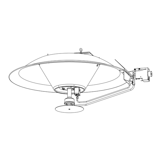
▲WARNING: ONCE THE BROODER IS ASSEMBLED AND BEFORE IT IS FIRST FIRED, YOU MUST CHECK FOR GAS LEAKS! USE A SOAP AND WATER SOLUTION AND APPLY AT ORIFICE FITTING, PILOT ASSEMBLY, AND FIELD CONNECTION AT THE GAS VALVE. COMPLETE ASSEMBLY FIGURE 4 MINIMUM CLEARANCES TO COMBUSTIBLES Minimum clearances to combustible materials shall be measured from the outer surface of the... -
Page 10: Brooder Installation
BROODER INSTALLATION 1. Locate brooders approximately 25’ to 40’ (8m to 12m) apart, in a row, as needed for bird comfort and building heat loss. If more than one row is desired, stagger rows for best heat distribution. FIGURE 5a 2. -
Page 11: Gas Connections
GAS CONNECTIONS 1. Gas piping for the house must be sized to be capable of satisfying the entire demands of the house should all equipment be operating at the same time. Please use Table 1 (taken from the National Fuel Gas Code) for the sizing of piping for the house. An example using this table is shown. -
Page 12: 7A) Instructions For Testing For Gas Leaks And Proper Gas Pressure
Item Number Part Number Description 30285000 VALVE,MANUAL BALL 1/2" 30241000 MALE FTG 45FLARE 3/8TUBEx3/8MPT 30241010 MALE FTG 45FLARE 3/8TUBEx1/2MPT 30523060 HOSE,3/8IDx6FT with 3/8"F SWIVEL FITTINGS 30523100 HOSE,3/8IDx10FT with 3/8"F SWIVEL FITTINGS Make sure connection is secure before turning on the gas. See section 7a for procedures to test for gas leaks before putting the brooders into operation. - Page 13 an approved, high quality leak detection solution. NEVER USE A MATCH OR OPEN FLAME TO CHECK FOR LEAKS. Once a leak has been located and repaired, repeat Steps 3 and 4 above. If there is an increase in pressure, it indicates that the LP gas container valve is not shut off tightly. Shut off the valve tightly and repeat Step 4 above.
- Page 14 SUPPLY PRESSURE BROODER MODEL GAS TYPE PRESSURE Minimum Maximum 4” 5” 14” Natural Gas Control (10.0 mbar) (12.4 mbar) (34.9 mbar) SRB40CR–N 3, 9 4” 4.5” 5.5” Natural Gas Controls (10.0 mbar) (11.4 mbar) (14.0 mbar) SRB40CR–L 10” 11” 14”...
-
Page 15: Gas Pipe Sizing Example
GAS PIPE SIZING EXAMPLE House Size: 40’ x 400’ Brooder Quantity: 14 Individual Brooder Capacity: 40,000 Btu/hr Second Stage Regulator Pressure: 14” W.C. Operating Pressure: 11”W.C., LP gas with all brooders operating Figure 7 STEP 1. Gas should be run at high pressure from the LP tank to the second stage regulator at the house. -
Page 16: Electrical Connections
(Table 1, continued) Tubing Size, O.D. Type L Nominal Pipe Size, I.D. Schedule 40 3/8” 1/2” 5/8” 3/4” 7/8” 1-1/8” 1/2” 3/4” 1” 1-1/4” 1-1/2” 2” 3” 4” 125 Ft. 1,731 4,878 9,950 150 Ft. 1,569 4,420 9,016 200 Ft. 1,343 3,783 7,716... - Page 17 No. of Brooders x 12.0VA x 1.25 Safety Factor = Transformer Size No. Brooders Minimum Transformer VA An optional Zone Control Power Supply Panel is available as an accessory (Part #43619050) to provide the required 24VAC for each #2 brooder. The Zone Control comes equipped with a 375VA transformer.
- Page 18 SCHEMATIC Figure 8 Form No.43539118 May 2013...
-
Page 19: Lighting And Shutdown Instructions
LIGHTING AND SHUTDOWN INSTRUCTIONS NO. 2 CONTROL (#VR8200M VALVE) 1. Turn gas control knob counterclockwise to “PILOT”. 2. Push and hold down the red reset button while you light the pilot. Immediately light the pilot with a match. Continue to hold the control/reset button down for about one (1) minute after the pilot is lit. -
Page 20: Ventilation
APPROXIMATE TEMPERATURE VERSUS CONTROL KNOB POSITION CONTROL KNOB POSITION Thermostat Range ºC 21º 26º 30º 33º 39º 43º 47º ºF 70º 79º 86º 91º 102º 109º 117º VENTILATION FOR YOUR SAFETY: Exhaust fans must be operating on an appropriate cycle when heating the building to avoid high concentrations of carbon monoxide and water vapor. -
Page 21: Cleaning And Annual Maintenance
CLEANING AND ANNUAL MAINTENANCE To keep your brooder in good operating condition, we recommend that after each crop you blow any dust and dirt from the brooder with compressed air. If at anytime you notice a lazy yellow flame as shown below then the brooder needs to be cleaned: CAUTION: TURN THE GAS AND ELECTRIC (IF EQUIPPED) SUPPLIES OFF AND ALLOW THE BROODER TO COOL DOWN BEFORE ATTEMPTING ANY... - Page 22 FIGURE 10 1. Release the main burner orifice fitting and pan from the burner by turning the swivel clamp. CAUTION: In order to prevent damage to the control arm tubing, first place your hand under the pan and allow the control to lower gently under its own weight. 2.
- Page 23 5. Clean both the inside and outside surfaces of the perforated emitter assembly with a large bristle brush (available as an accessory, Part No. 43295020) or other large bristle type brush; then use compressed air to remove any burnt dust or dirt particles from the emitter. 7.
-
Page 24: Troubleshooting
10. Remove and clean the thermocouple when necessary using acetone liquid cleaner. NOTE: After reassembly of all components, check the gas connections at the burner and the gas valve for leaks. Use a heavy soapsuds solution. DO NOT use an open flame to check for gas leaks NOTE: After reassembly of all components, check the gas connections at the burner and the gas... -
Page 25: Replacement Parts Guide
REPLACEMENT PARTS GUIDE SRB40CR-2 SRB40CR-3 SRB40CR-9 Item No. Part No. Description 02166070 #8-32 x 1/2" Pan Head Screw 02167040 #8-32 Hex Locknut - Keps 02167020 #10-24 Hex Locknut - Keps 02167019 1/4-20 Hex Locknut – Keps SS 02259000 1/4-20 x 5/8" Hex Head Screw SS 02309000 1/4-20 x 2"... - Page 26 43539118 Installation Manual (not shown) 43534100 Kit, Complete Fastener (not shown) 43311930 Label Holder Plate 43311010 Label, Nameplate/Rating Plate 43311180 Label, Soot/Hot Surface Hazard Screws, nuts and washers are standard hardware items and can be purchased at any local hardware store. ALL ILLUSTRATIONS ARE INTENDED TO GIVE THE GENERAL IMPRESSION OF UNITS ONLY.
- Page 27 GAS-FIRED PRODUCTS LIMITED WARRANTY LIMITED WARRANTY Gas-Fired Products, Inc. (GFP), the manufacturer, warrants the original owner of any Space-Ray Poultry Heating Product that it will be free from defects in material or workmanship under normal use and service. The heater(s) shall be installed, used and maintained strictly in accordance with the manufacturer's instructions.
- Page 28 No Representative is authorized to assume for the manufacturer, any liability except as set forth above. For the name of your nearest distributor in case of claim under this warranty, contact: Space-Ray Poultry Heating Products / Gas-Fired Products, Inc. / 305 Doggett St., PO Box 36485 / Charlotte, NC 28236 / Phone: (704) 372-3488 / Fax: (704) 332-5843 / email: info@spaceray.com.
Need help?
Do you have a question about the SRB40CR and is the answer not in the manual?
Questions and answers