Advertisement
INSTALLATION INSTRUCTIONS FOR STK-LIN60-B KIT
[FOR USE IN ALLUMEDLX60TEN-B, ALLUME60TEN-B, DRL4060TEN-B, AND DRL6060TEN-B FIREPLACES]
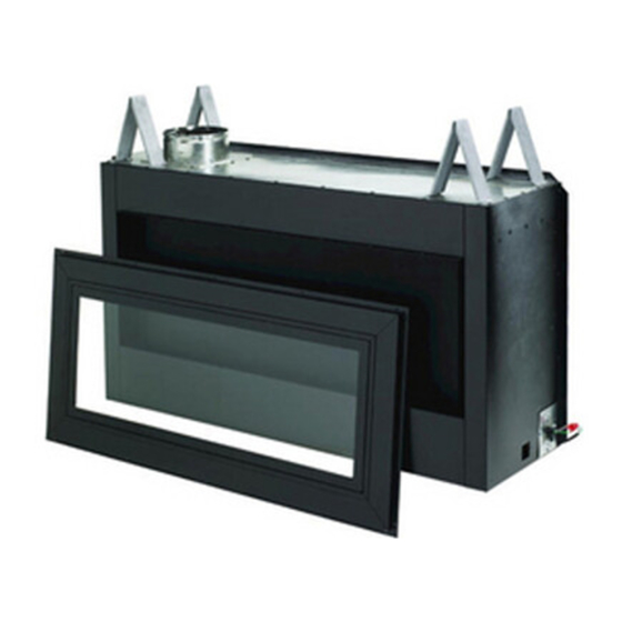
Kit Components
2 ea. Nailing Flange side
2 ea. Tile Stop L/R
2 ea. Tile Stop Top/Bottom
2 ea. Sight Obstructor
1 ea. Standoff Heatshield
1 ea. Door Access Cover
1 ea. Fireboard Assembly
1 ea. Glass Door
1 ea. Rear Standoff Assembly
1 ea. Barrier
22 ea. #10 Hex Head Screw
15 ea. #8 Phillips Head Screw
36 ea. Bugle drywall Screws
STK-LIN60-B KIT
Cat. No.
Model Number
F4410
STK-LIN60-B KIT
Table 1
See Figure 1
INSTALLER: Leave this manual with the appliance
CONSUMER: Retain this manual for future reference
IMPORTANT NOTICE
STK-LIN60-B KIT IS REQUIRED FOR UPGRADING FIREPLACE
TO A SEE-THRU APPLICATION.
IMPORTANT NOTICE
BLOWER USE IS NOT COMPATIBLE WITH THE STK-LIN60-B
KIT.
WARNING
This kit must be installed by a qualified installer,
service agency, or gas supplier at the time of the
fireplace installation. These instructions must
be used in conjunction with the installation and
operation manual provided with the fireplace.
TOOLS REQUIRED (not included)
Electric Drill/Driver Gun
Phillips Screwdriver Bits
5/16 Nut Driver
5/16" Wrench
Description
Kit, Linear 60 See-Thru
NOTE: DIAGRAMS & ILLUSTRATIONS ARE NOT TO SCALE.
P/N 901058-00 REV. NC 07/2020
Rear Standoff
Assembly
Figure 1 - STK-LIN60-B KIT
GENERAL INFORMATION
The STK-LIN60-B KIT is designed to upgrade the fireplace to a
see-thru application.
When Installing this kit, reference the framing dimensions for the
see-thru application and follow the framing instructions shown on
the fireplace installation Instructions. Follow all other installation
requirements for the fireplace as detailed in the installation manual.
IMPORTANT! CONVERT THE FIREPLACE TO A SEE-THRU
APPLICATION BEFORE INSTALLING INTO THE FRAMING.
REFER TO INSTALLATION INSTRUCTIONS AND CARE AND OPERA-
TIONS MANUAL (IICO) FOR FRAMING DETAILS BEFORE INSTALLING
THIS KIT.
ALL WARNINGS AND PRECAUTIONS IN THE INSTALLATION AND
OPERATION MANUAL PROVIDED WITH THE FIREPLACE APPLY TO
THESE INSTRUCTIONS.
HEARTH PRODUCTS
KITS AND ACCESSORIES
STK-LIN60-B KIT
Sight Obstructors
Standoff
Heatshield
1
Advertisement
Table of Contents

Related Manuals for IHP STK-LIN60-B KIT


Summary of Contents for IHP STK-LIN60-B KIT
- Page 1 STK-LIN60-B KIT IS REQUIRED FOR UPGRADING FIREPLACE TO A SEE-THRU APPLICATION. GENERAL INFORMATION IMPORTANT NOTICE The STK-LIN60-B KIT is designed to upgrade the fireplace to a see-thru application. BLOWER USE IS NOT COMPATIBLE WITH THE STK-LIN60-B When Installing this kit, reference the framing dimensions for the KIT.
- Page 2 ALLUMEDLX60TEN-B and DRL6060TEN-B model only, disconnect blower assembly power cord from the fireplace control module harness. Discard blower assembly and blower harness as blowers are not compatible on a see-thru application. Preparing Fireplace for See-Thru Application 1. Install rear standoff assembly, as shown in Figure 2, using eight (8) of the #10 hex head screws.
- Page 3 Sight Obstructor Door Access Cover Supports Partially Loosen, Both Sides Do Not Remove Partially Install Figure 6 Both Sides Upper Heatshield Door Access Cover Support Door Access Cover Slot Figure 5 8. Partially install two (2) #8 Phillips head screws into the upper left and right tile stop mounting holes.
- Page 4 13. Proceed with installation of the fireplace into the framing per instructions in the Installation and Operation Manual provided with the fireplace. 14. Once the fireplace is installed in the framing, install the nailing flanges. Loosen (DO NOT REMOVE) the three (3) hex head Mounting mounting screws on both sides of the fireplace shown in Figure Screws...
- Page 5 FINISHING FIREPLACE The appliance is designed to mate with 1/2” wall sheathing materials such as drywall, plywood, wood composites, or non-combustible materials. Finishing and Sealing Joints All joints between the finished wall sheathing and the appliance must be sealed with non-combustible materials. Sealants, such as caulk or mastic used to seal the gap between the wall and the fireplace, should be rated at a minimum continuous exposure to 300 ºF.
- Page 6 Innovative Hearth Products (IHP) reserves the right to make changes at any time, without notice, in design, materials, specifications, prices and also to discontinue colors, styles and products. Consult your local distributor for fireplace code information. Printed in U.S.A. © 2020 Innovative Hearth Products P/N 901058-00 REV.
Need help?
Do you have a question about the STK-LIN60-B KIT and is the answer not in the manual?
Questions and answers