
Related Manuals for CIMLINE X2


Summary of Contents for CIMLINE X2
- Page 1 Stand Alone Compressor with Boom Arm Owner/Operators Manual 2601 Niagara Lane · Plymouth, MN 55447 · (763) 557-1982 · (800) 328-3874 · Fax (763) 557-1971 Part # 301-000-000 6/22/2021...
- Page 2 WARNING Operating, servicing and maintaining this machine can expose you to dust containing crystalline silica and engine exhaust which contains chemicals that are known to the State of California to cause cancer, birth defects, or other reproductive harm. For more information, go to www.P65Warnings.ca.gov.
-
Page 3: Table Of Contents
Installation ..................12-15 Prior to Installation ..............12 Raising the Boom Column ............12 Initial Start Up ................13 Lifting the X2 ................14 Securing the X2 ................15 Operating the X2 ................16-18 Start Up .................. 16-17 During Operation ................. 18 Shutting Down ................ -
Page 4: Shipping Papers And Information
This manual contains the basic information required to operate, maintain and repair the CIMLINE X2 you have purchased. The use of this manual insures accurate adjustments, operation and proper lubrication of your equipment. -
Page 5: General Safety Overview
General Safety Overview IMPORTANT: READ BEFORE OPERATING EQUIPTMENT You are in a position to ensure the safety of yourself and those around you. Lack of attention to safety can result in: accidents, personal injury, reduction in efficiency, and worst of all - loss of life. Watch for safety hazards and correct them promptly. Understanding the proper operation of this equipment is critical to its safe operation. - Page 6 NOTICE Personal Protective Equipment Required The compressed air output from the X2 will produce dust and flying debris. The operator and anyone working in close proximity to the air nozzle must always wear personal protective equipment (PPE). The PPE must be well maintained and in proper working order.
- Page 7 WARNING SILICA DUST HAZARD Using a compressor to clean pavement or cracks may expose workers to crystalline silica dust. Exposure to crystalline silica dust can cause cancer or silicosis. A respirator is required for ANYONE working in close proximity. CAUTION NOISE HAZARD Continual exposure to excessive noise can lead to loss of hearing.
- Page 8 DANGER POISONOUS GAS Using a gas powered compressor indoors WILL KILL YOU IN MINUTES. The compressors exhaust contains carbon monoxide, a poisonous gas you cannot see or smell. NEVER use inside a home, garage, or confined space. EVEN IF doors ...
- Page 9 CAUTION BURN HAZARD Contact with the hot surfaces of the compressor, including the engine and muffler, may result in burns. NEVER reach inside the compressor enclosure during or immediately after operation. NEVER change the compressor oil or service the engine when ...
-
Page 10: Weights And Dimensions
Weight and Dimensions Weight without hose and wand = 975 lbs Fuel tank capacity = 5 gallons Compressor oil capacity = 2 gallons Compressor output = 70 cfm @ 100 psi Folded Boom 58” 44” 125” 53” to 68” From Bed 40”... -
Page 11: Safe Operation
Extended Boom 58” 168” Safe Operation NEVER leave compressor unattended while the engine is running. NEVER operate compressor on a grade over 15⁰ (roughly 25% or 1 : 4 grade). NEVER hang from the boom. Make sure the boom latch is fully engaged when the boom is extended over the ... -
Page 12: Installation
2) If the required clearance is greater than 40” the boom column has to be raised to the correct height. NOTICE: If the required clearance is above 55” the X2 can not be installed on that vehicle. Raising the Boom Column... -
Page 13: Initial Start Up
Installing the X2 Continued... Perform Initial Start Up 1) Remove all packaging and other debris from the compressor, both inside and out. 2) Remove the lower panel on the exhaust side of the compressor and attach the battery cable to the battery. -
Page 14: Lifting The X2
Installing the X2 Continued Lifting the X2 1) Using a forklift approach the X2 from the non-column side end. Insert forks into the lifting pockets being careful not to damage the air hose of valve. WARNING! The X2 is top heavy and has a center of gravity near the vertical column. -
Page 15: Securing The X2
Permanent Mounting Options The X2 is supplied with foot pads that allow for either bolting or welding the unit to the truck bed. For installation using either of these methods consult your vehicles owners... -
Page 16: Operating The X2
Operating the X2 Start up NOTICE: Keep compressor as level as possible during operation. NEVER operate the compressor on grades greater than 25% (15⁰) NOTICE: The compressor may experience high temperature shutdowns when operated in temperatures above 100⁰ F. NOTICE: The compressor and engine are not designed to work in an altitude above 4000ft. - Page 17 Operating the X2 Continued... Start up continued 7) Make sure the area around the compressor is free of debris, flammables and other items that may block the air flow. NOTICE: It is best practice to not haul gasoline or other flammables in the truck bed with the compressor.
-
Page 18: During Operation
Operating the X2 Continued... During operation 1) Once the engine has warmed up (3 to 5 minutes), open the air valve (handle paral- lel to the line) and begin work. 2) As work progresses, the truck can be slowly moved (10 MPH or less) as required. -
Page 19: General Maintenance
General Maintenance Fuel Use unleaded gasoline only with a pump octane rating of 87 or higher. The gasoline must not have more than 10% ethanol. WARNING! Gasoline is extremely flammable liquid and vapor. Negligence or improper care can cause fire leading to serious personal injury. NOTICE: E15, E20, and E85 are not approved for use by Kohler and should not be used. -
Page 20: Engine Service
General Maintenance Continued... The Boss Bullet G consist of two main maintenance components; the engine by Kohler and the compressor system by Boss. Cimline, inc. warranty does not cover the engine or compressor. The engine is covered under separate warranty from Kohler. Visit Kohler’s ... - Page 21 General Maintenance Continued... Every 25 hours or weekly Check engine air cleaner paper element. Service / replace low profile air filter pre-cleaner. Every 50 hours or weekly Inspect belts. At the first 50 hour increment, install the Boss 50 hour maintenance kit. ...
-
Page 22: Storage Preparation
3) Remove the key and attach it to the compressor to prevent losing it. 4) Relieve any system pressure. 5) Grease the boom pivot. 6) When cool, either cover the compressor and/or move the X2 into an enclosure. NOTICE: DO NOT leave or store the compressor outside in the rain or snow without a cover that prevents moisture from entering the unit. -
Page 23: Removal From Storage
General Maintenance Continued... Removal from Storage 1) Remove the cover and inspect your unit as described in Initail Start up section of this manual (see page 13) 2) Clean the unit and check for nests in the compressor, the air filters, engine area, as well as the exhaust. -
Page 24: Troubleshooting
Troubleshooting Problem Probable Cause Engine won’t start Dead battery Out of fuel Plugged fuel filter Loose battery cables Low engine oil level Fouled spark plug Bad high discharge temp switch Engine overheating Oil level Dirty engine oil Blocked or dirty vents, fans, fins, and outlets Unplanned Shutdown Out of fuel Compressor oil level... - Page 25 Troubleshooting Continued… For issues generally related to the compressor refer to the Boss Bullet G manuals’ Maintenance and Trouble shooting section. For Issues directly related to the engine refer to the Kohler Command Pro manual.
-
Page 26: Component Identification
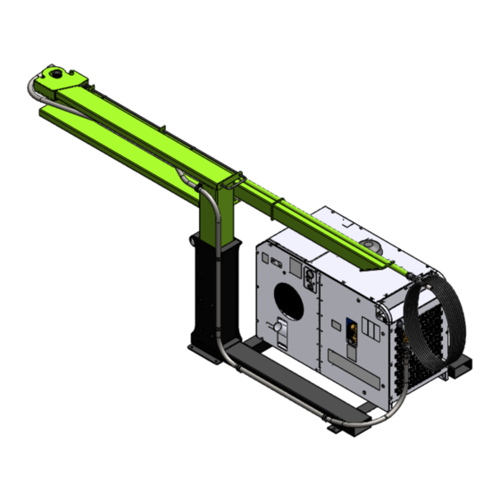
Identifying Components Manual Boom Release Overview Boom Latch Boom Rest and Pin P/N 101002 Boom Boom Column Bullet 2 Compressor P/N 301-058-004 Boom Latch Pivot Pin Plastic Chanel Guide Latch Pin P/N 301-057-000 Latch Body Swivel Grease Zerk P/N 301-060-601... - Page 27 Identifying Components Continued… Bullet 2, Controls Side Compressor Oil Fill Port Engine Access Panel Compressor air intake Tie Down Point Engine Oil Dipstick Access Compressor Engine cooling air intake Tie Down Point Column Foot Pad Lifting tube Column Mounting Bolts Compressor oil sight glass Fuel Tank Filler Neck Compressor Access Door...
- Page 28 Identifying Components Continued… Bullet 2, Exhaust Side Tie Down Point Compressor Engine Muffler & Exhaust Foot Pad Battery Access Foot Pad Panel Not Shown Lifting tube Bullet 2, Oil Cooler End Air Valve Air line P/N 301-061-601 Lifting tube...
- Page 29 Identifying Components Continued… Bullet 2, Compressor Access Door Compressor Air Filter Compressor Oil Sump Compressor Oil Filler Cap Dust Purge / Duck Bill Valve Coalescing Filter Regulator DO NOT ADJUST Compressor Oil Cooler Compressor Compressor Oil Sight Compressor Oil Filter Compressor Oil Drain Plug Compressor Oil Filter View shifted to show oil drain plug...
- Page 30 Identifying Components Continued… Bullet 2, Panels Removed, Exhaust Side Compressor Air Filter Maintenance Indicator Compressor Oil Cooler Muffler Drive Belt Engine Oil Filter Electric Fan Starter Battery Engine Oil Drain Fuel Tank Fuel Vapor Carbon Canister Belt Tensioning Bolt Pressure Relief Valve...
- Page 31 Identifying Components Continued… Bullet 2, Kohler Engine Engine Air Filter Engine Dip Stick Engine Oil Fill Point Fuel Filter Engine Oil Filter Engine Oil Drain Line...
-
Page 32: Service Part List
Service Parts Any parts orders or service problems relating to CIMLINE equipment should be directed to the CIMLINE Parts Department at either (763) 557-1982 or (800) 328-3874. When ordering parts, please have the following information available. Serial Number: Model Number:... - Page 33 Compressor Service Parts Cimline Part # Description 301-900-000 Air Filter Boss Bullet 2 301-901-000 Oil Filter Boss Bullet 2 155163 Spin On Coalescer Boss 301-902-000 Compressor Oil - Shield Works - 5L 301-903-000 Valve - Relief 1/4” 200 psi 301-904-000...
-
Page 34: Notes
Notes:... -
Page 36: Warranty
2601 Niagara Lane · Plymouth, MN 55447 · (763) 557-1982 · (800) 328-3874 · Fax (763) 557-1971...
Need help?
Do you have a question about the X2 and is the answer not in the manual?
Questions and answers