Table of Contents
Advertisement
Quick Links
Advertisement
Table of Contents

Related Manuals for PERCo TTD-03.1


Summary of Contents for PERCo TTD-03.1
- Page 1 Electromechanical Box Tripod Turnstile TTD-03.1 OPERATION MANUAL...
- Page 2 Electromechanical Box Tripod Turnstile TTD-03.1 Operation Manual...
-
Page 3: Table Of Contents
CONTENTS APPLICATION ........................3 OPERATION CONDITIONS ....................3 TECHNICAL SPECIFICATIONS .................... 3 DELIVERY SET ........................4 Standard delivery set ....................... 4 Optional equipment supplied on request ................4 PRODUCT DESCRIPTION ....................5 Main features ........................5 Design ..........................5 5.2.1 Turnstile housing ..................... -
Page 4: Application
You have purchased a high quality product, which will be long lasting in operation provided that installation and operation rules are observed. The operation manual for the TTD-03.1 electromechanical box tripod turnstile (hereinafter referred to as the “turnstile”) contains data that is necessary for the most full usage of operating advantages of the turnstile as well as chapters on packaging, installation and maintenance. -
Page 5: Delivery Set
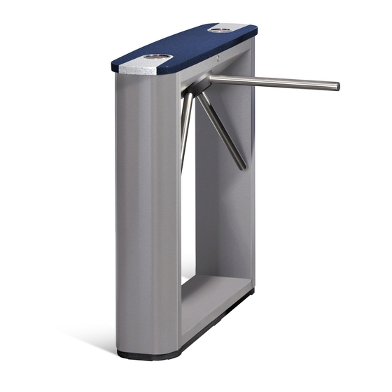
Siren (for alerts on unauthorized entry attempts) ................1 SORMAT PFG IR M10-15 anchor bolts..................4 Note: WRC kit consists of a receiver and 2 transmitters (tags) with operation range up to 40 m. Fig. 1 TTD-03.1 box tripod turnstile. Overall dimensions... -
Page 6: Product Description
TTD-03.1 Electromechanical Box Tripod Turnstile 5 PRODUCT DESCRIPTION 5.1 Main features • The turnstile can be operated both autonomously with the RC-panel or WRC and with an ACS. • At the power supply switching off the turnstile remains in the set position in both directions (closed, if the particular direction was closed at the moment of the power switching off, or open, if it was open at the moment of the power switching off). -
Page 7: Remote Control Panel
Operation manual Fig.2 TTD-03.1 box tripod turnstile. Overall view 1 – turnstile housing; 2 – outer panel; 3 – turnstile cover;4 – indication module; 5 – barrier arm; 6 – turnstile cover lock; 7 – hub; 8 – mechanical release lock; 9 – RC-panel with cable;... -
Page 8: Control Board
TTD-03.1 Electromechanical Box Tripod Turnstile Control commands and corresponding indication on RC-panel for impulse and potential modes are indicated in Table 2 and Table 3. At the turnstile power supply switching-on the turnstile initial state is closed (the mechanical release lock (8) should be locked with the key). -
Page 9: Input And Output Signals And Their Parameters When Operating The Turnstile
Operation manual • turnstile power supply connector block – "XT3" ("+12VDC"); • remote indicator connector blocks (open/closed, one indicator per each direction) – "XT4" and "XT5" ("Light A" and "Light B" accordingly); • "J1" connector for turnstile control mode selection (see below); •... - Page 10 TTD-03.1 Electromechanical Box Tripod Turnstile Fig. 5 Control elements of an external device a normally open relay contact Fig. 6 ACS control element – circuit with open-collector output Fig. 7 Output cascades for PASS A, PASS B, Ready, Det Out and Alarm...
-
Page 11: Control Modes Of The Turnstile
Operation manual The relays “PASS A” (contacts “PASS A” and “Common”), “PASS B” (contacts “PASS B” and “Common”), “Ready” (contacts “Ready” and “Common”), “Detector” (contacts “Det Out” and “Common”) and “Alarm” (contacts “Alarm 1” and “Alarm 2”) have normally open contacts. The “Common”... -
Page 12: Operation With The Rc-Panel
TTD-03.1 Electromechanical Box Tripod Turnstile The above devices can be connected to the turnstile as follows: All together simultaneously; • One of device separately; • In any combination with each other. • Note: At the parallel connection of the above devices to the turnstile the superposition of control signals from those devices may occur. -
Page 13: Operation With The Wireless Remote Control
Operation manual 5.3.2 Operation with the wireless remote control Operation of the turnstile with the WRC is similar to that with the RC-panel. The buttons on the WRC tag act the same way as those on the RC-panel. The operation manual for the WRC is supplied within the delivery set of that item. 5.3.3 Operation with an ACS controller At the pulse control mode control over the turnstile via an ACS controller is similar to that with the RC-panel. -
Page 14: Operation Contingencies And Response
TTD-03.1 Electromechanical Box Tripod Turnstile The remote indicators can be connected to the connector blocks “XT4” (“Light A”) and “XT5” (“Light B”). At that the “Light A” (“Light B”) relay is active (the voltage is supplied to relay coil), when the “Green arrow”... -
Page 15: Safety Requirements
Operation manual surface. The sticker corresponds to Fig.4. To get access to it, remove the turnstile cover (3). Undo two M6 nuts, fixing the upper parts of the left-side outer panel (2). Lift the outer panel and take it off carefully. -
Page 16: Tools And Equipment Required For Installation
TTD-03.1 Electromechanical Box Tripod Turnstile To ensure accurate passage tracking when the turnstile is operated with an ACS, it is recommended to create the passage area in such a way that the barrier arm turning in the direction of movement must be at the angle of not less than 70° (Fig. 9). - Page 17 Operation manual Drill the holes for anchor bolt sleeves for fixing of the turnstile housing (see Fig. 10). If you lay the cables under the floor surface, prepare the electric raceway to the cables laying zone of the turnstile housing (see Fig. 10). Insert the sleeves for the anchor bolts into the holes so that they do not stick out above the floor surface.
- Page 18 TTD-03.1 Electromechanical Box Tripod Turnstile Fig.11 Cables layout inside the turnstile housing 1 – power supply cable, 2 – RC-panel / WRC / ACS controller cable, 3 – turnstile cable, 4 – indication cable, 5 – CLB, 6 – control mechanism, 7 – intrusion detector, 8 – siren;...
- Page 19 Inside the turnstile sections, it is possible to install access card readers as manufactured by PERCo (IR03.1, MR07 OEM, RP-15.2), and third-party manufacturers. The choice of the type of readers, their acquisition and installation into the product is carried out by the customer (installer) in accordance with the design of the pass-through and the characteristics of the access control system and the control controller.
-
Page 20: Connection Layout
TTD-03.1 Electromechanical Box Tripod Turnstile 8.1 Connection layout Fig.13 Connection layout... -
Page 21: Operation Instructions
Operation manual Table 1 Legend to Fig. 13. Legend Item Q-ty Note A1*, A2* Remote indicators Remote indicator power supply Siren, 12 V DC Turnstile power supply Control mechanism A8, A9 Indication modules A10* Emergency unblocking device A11* Intrusion detector Remote control panel A13* Wireless remote control kit... - Page 22 TTD-03.1 Electromechanical Box Tripod Turnstile Table 2 Pulse control mode (the jumper is set on the connector J1) Response № The turnstile Indication Indication on the Actions to do to the barrier arm operating modes on the RC turnstile turning The red The two “Red...
-
Page 23: Operating Modes Of The Turnstile At Potential Control Mode
Operation manual In the “Single passage in the set direction” mode the turnstile will close automatically after a person’s passage in the set direction. The turnstile will also close automatically, if the passage is not made within 5 sec. In the “Bidirectional single passage” mode after the passage in one direction the countdown of the passage waiting time (5 sec) for the opposite direction is recommenced. -
Page 24: Mechanical Unblocking Of The Turnstile
TTD-03.1 Electromechanical Box Tripod Turnstile Fig. 14 Anti-panic drop arms application When using the standard barrier arms, it is possible to provide free passage through the turnstile by unblocking it with the mechanical release key. The sequence of actions is described in Clause 5.10. - Page 25 Operation manual 1. Unlock the turnstile cover lock (6) with the key and turn it clockwise up to the stop (the lock cylinder moves out of the case) 2. Shift the turnstile housing cover to the right up to the stop (slight push is allowed). Lift the cover and turn it over to gain access to the indication module connectors;...
-
Page 26: Transportation And Storage
2. mount the turnstile cover (3) in the reverse order as described above. The housing cover mounting does not need much effort. In case of any defects revealed during visual check please apply to PERCo Technical Support Department. 11 TRANSPORTATION AND STORAGE The turnstile in the original package can be only delivered by means of transportation with covering facilities (railroad cars, covered truck car bodies, vessel holds) and by air transport. -
Page 27: Appendix А Control Signal Algorithm At Pulse Control Mode
Operation manual Appendix А Control signal algorithm at pulse control mode Note! For the RC-panel: • active front — pressing of the relevant button on the RC-panel; • low level — the relevant button on the RC-panel has been pressed; •... -
Page 28: Appendix B Control Signal Algorithm At Potential Control Mode
TTD-03.1 Electromechanical Box Tripod Turnstile Appendix B Control signal algorithm at potential control mode Both directions are closed (closed for entry and exit) - There is a high level at contacts “Unlock A” and “Unlock B” or there is a low level at contact “Stop”. - Page 29 PERCo Polytechnicheskaya str., 4, block 2 194021, Saint Petersburg Russia Tel: +7 812 247 04 64 E-mail: export@perco.com support@perco.com www.perco.com...
- Page 30 www.perco.com...
Need help?
Do you have a question about the TTD-03.1 and is the answer not in the manual?
Questions and answers