Table of Contents
Advertisement
Quick Links
Advertisement
Table of Contents
Troubleshooting

Related Manuals for Vertiv Liebert LVC


Summary of Contents for Vertiv Liebert LVC
- Page 1 Liebert® LVC User Manual...
- Page 2 Vertiv Co. Ltd. China Website: www.vertivco.com Email: support@Vertivco.com Customer Service Hotline: 4008876510 Asia-Pacific Website: www.vertivco.com Email: overseas.support@Vertivco.com For Technical Support, users may contact the nearest Vertiv Co. local sales office or service center.
- Page 3 Purpose of the Document This document applies to the Liebert LVC used in precision air conditioners and cooling solutions which maintain an optimal environmental control of technological ecosystems at minimal operating costs. This document gives an overview of the technical specification and parameters. The figures used in this document are for reference only.
-
Page 4: Table Of Contents
Chapter 3: Spray Cooling Module (Optional Component) ............18 3.1. Introduction of Spray Cooling Module .............................. 18 3.2. Requirements of Spray Water Quality .............................. 18 3.3. Pipe Installation of Spray Water System ............................19 3.3.1. Water Softener ......................................20 Vertiv | Liebert LVC | User Manual... - Page 5 Chapter 5: Maintenance and Troubleshooting..................29 5.1. Maintenance ..........................................29 5.1.1. Maintenance of Condenser Components ..........................29 5.1.2. Maintenance of Spray Water System.............................31 5.2. Troubleshooting ........................................31 Appendix I: Circuit Diagram ....................35 Appendix II: Hazardous Substances ..................37 Vertiv | Liebert LVC | User Manual...
-
Page 6: Chapter 1: Product Overview
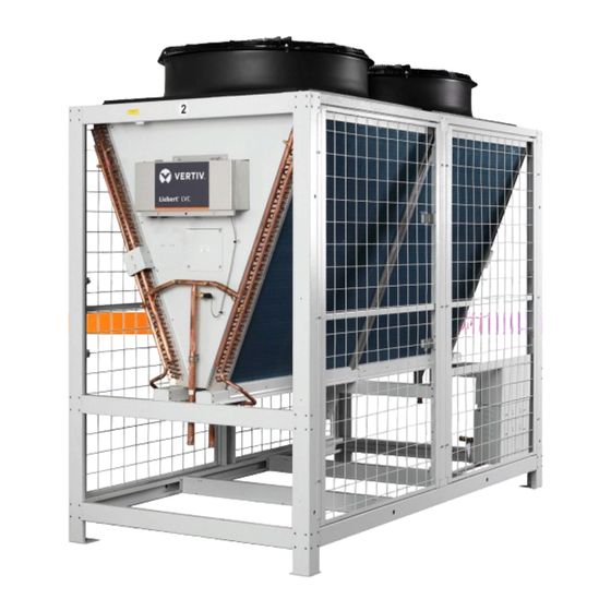
Chapter 1: Product Overview 1.1. Model Description Liebert LVC is a professional equipment, which is situated in restricted area and can be accessed by authorized personnel only. This chapter introduces the nomenclature, main components and technical parameters of the Liebert LVC. The main component of the condenser includes heat exchanger, fan, fan speed controller and pressure sensor. -
Page 7: Nomenclature
Digit 16 Order Identifier 380-415V/3ph/50Hz/60Hz+N 380-415V/3ph/60Hz+N Digit 17 Order Identifier Digit 11 Energy – Saving Kit Digit 18 Order Identifier None Pump Energy Saving Module Spray Cooling Module Spray Cooling Module + Pump Energy Saving Module Vertiv | Liebert LVC | User Manual... -
Page 8: Technical Parameters
• Figure 1-2 shows the serial number labels to determine system 1 and 2. There will be stickers with serial numbers pasted on LVC condensers to identify each system. • There is a height difference of the condenser unit due to the different heights of individual fan model. Vertiv | Liebert LVC | User Manual... -
Page 9: Mounting Base Dimensions
• It is recommended to use M12 x 4 bolts to fix the mounting base to the round holes at the instal- lation site. • It is recommended to use rubber cushions between mounting foot and the installed base to ab- sorb vibration. Vertiv | Liebert LVC | User Manual... -
Page 10: Parameters Of Operating Environment
Ambient Temperature -40 °C~ + 70 °C Ambient relative humidity 5%RH ~ +70%RH Total transportation and storage time should not exceed six months, otherwise the Storage time performance of the system need to re-calibrated. Vertiv | Liebert LVC | User Manual... -
Page 11: Chapter 2: Installation
Figure 2-1 and 2-2 (Considering the single fan condenser for example). Figure 1-1 Forklift Direction 1 Figure 1-2 Forklift Direction 2 When a crane is used, refer to Figure 2-3 to lift the package. Vertiv | Liebert LVC | User Manual... -
Page 12: Unpacking
Remove the frame package and foam of the condenser without removing the protection cardboard of the fins. The protection cardboard of fins and the cushion pad of U tube located at the end of the condenser should be removed after the condenser is in its installation position. Vertiv | Liebert LVC | User Manual... -
Page 13: Inspection
1.1.3. Inspection After the product arrival, you should check the accessories against the packing list. If any parts are found missing, or damaged, please report to the local offices of the carrier and Vertiv Co. immediately. 1.2. Installation Notes The installation notes of the condenser are as follows 1. - Page 14 Installation Figure 1-4 System Serial Number Identification Figure 1-5 Spread Evenly Installation Layout Overhead View Vertiv | Liebert LVC | User Manual...
-
Page 15: Space Requirements
• The engineered mounting bracket requires four sides to be hollowed out, which can be ventilated freely. In the following Figure 2-8 & 2-9. “h” is engineered mounted bracket height “h1” is enclosure height, “a” is the Vertiv | Liebert LVC | User Manual... - Page 16 • In Figure 2-8 the space requirement is based on the area of the building to provide the minimum spacing for air circulation within 10 m around the installation site. If the air circulation is not sufficient, please consult Vertiv personnel for technical confirmation.
- Page 17 0≤h<0.5 ≥2.0 LVC088 / LVC106 ≥0.5 ≥1.6 0≤h<0.5 ≥2.2 ≤1 ≥1.5 ≥1.0 LVC140 ≥0.5 ≥1.8 0≤h<0.5 ≥2.5 LVC152 / LVC170 ≥0.5 ≥2.0 Figure 1-9 Side by Side Installation Space Requirement Vertiv | Liebert LVC | User Manual...
- Page 18 The quantity of installed condensers between 30-50 Model h (engineered mounting bracket height) 0.5≤h<1.0 ≥2.0 ① LVC088 / LVC106 ≥1.0 ≥1.6 0.5≤h<1.0 ≥2.2 ① LVC140 ≤1 ≥1.5 0.03 ② ≥1.0 ≥1.8 0.5≤h<1.0 ≥2.4 ① LVC152 / LVC170 ≥1.0 ≥2.0 Vertiv | Liebert LVC | User Manual...
-
Page 19: Installation Procedures
Table 2-1 & 2-2. If enclosure height more than 1m, it is must to increase engineered mounting bracket height. Please consult Vertiv personnel for technical confirmation. 5. The maximum number of side by side condenser which can be installed is 10. -
Page 20: Connecting External Power
A condenser has two systems. It is required to the condenser No.1 system and No.2 system to powered supply respectively. Select the appropiate power supply cables (L1/L2/L3/N/PE) and control cables (two core wires) of the condenser according to the Full Load Current and the Installation Distance as shown in Table 2-4. Vertiv | Liebert LVC | User Manual... - Page 21 To protect against the thunderstorm conditions, grounding line must be connected with the bolt of condenser lighting protection connection in the electrical control box of No.1 system and No.2 system respectively. Figure 1-12 Connection Figure of External Power Cables Vertiv | Liebert LVC | User Manual...
- Page 22 • All wiring must be fixed by clamp before entering the electrical control box. • External power cables and compressor signal cables should be connected to the corresponding terminals in the electrical box. Vertiv | Liebert LVC | User Manual...
-
Page 23: Chapter 3: Spray Cooling Module (Optional Component)
• The use of tap water without softening treatment will cause nozzle clogging, fine scaling & cor- rosion, water pump damage, affects the normal operation of the spray system and the effective convection heat transfer of the condenser. Vertiv | Liebert LVC | User Manual... -
Page 24: Pipe Installation Of Spray Water System
The water pressure and diameter of each branch pipes should meet the water consumption of the corresponding spray cooling module. The water consumption of each model as shown in Table 3-2. Vertiv | Liebert LVC | User Manual... -
Page 25: Water Softener
• The softener should be installed in drainage piping site to easily drained the waste water during the operation of softener. • Monitor the water harness of softener regularly. Add the industrial salt and replace the resin in- time. Vertiv | Liebert LVC | User Manual... -
Page 26: Water Filter
No.1 system and No.2 system parameters in the controller C44 to 1, and value of C45 to 1. 6. Take a trial run of the spray cooling module at least for 3min. It is required to observe the smooth operation Vertiv | Liebert LVC | User Manual... -
Page 27: Antifreeze Maintenance Of Spray Water System
No.1 system and No.2 system (as shown in Figure 3-5). Drain the water of spray cooling module, so that compressed air can be used to blow the residual water. Vertiv | Liebert LVC | User Manual... -
Page 28: Antifreeze Maintenance Of Spray Water System
Refer to Section 3.5 Pre-commissioning (Trial running) of Spray Cooling Module for trial operation in ‘Liebert LVC User Manual’. Vertiv | Liebert LVC | User Manual... -
Page 29: Chapter 4: Application Of Fan Speed Controller
NTC failure Query the history alarm data in The latest saved 100 historical alarms can be queried real time Vertiv | Liebert LVC | User Manual... -
Page 30: Operation Description Of Hmi
2 when the fan speed controller is powered on initially. The display order is shown in Figure 4-2. Figure 4-2 Display Order of the Initial Interface • The “16.1” is only an example, and the actual value is determined by the sampling result Vertiv | Liebert LVC | User Manual... -
Page 31: Main Menu Interface
‘A__’ (the symbol of current alarm main menu). The switching operation process and order of the current alarm submenu are shown in Figure 4-5, and the Current alarm main menu ID significances are shown in Table 4-2. Vertiv | Liebert LVC | User Manual... - Page 32 Pressure sensor failure EEPROM read fault alarm Hardware over current Bus over voltage Communication failure Spray high pressure alarm Spray low pressure alarm NTC failure Fan not configuring alarms Bus under voltage alarm Vertiv | Liebert LVC | User Manual...
-
Page 33: Historical Alarm Main Menu Interface
Historical alarm main menu interface H―― DOWN No Alarm 99.0 Figure 4-6 Switching Operation Processes and Orders of the Historical Main Menu • The alarm is displayed as “alarm number” + “alarm code”. Vertiv | Liebert LVC | User Manual... -
Page 34: Chapter 5: Maintenance And Troubleshooting
No. 2 system of the condenser, as shown in the Figure 5-1. During cleaning, ensure the power is off, electrical box be sealed well and control the blow-off angles is less than 45º between blowing off direction and condenser airflow direction. Figure 5-1 Cleaning Window Vertiv | Liebert LVC | User Manual... - Page 35 The fan speed controller is inside the electrical control box, refer to Figure 5-2 to remove the fan speed controller board, there are 4 screws in each corner of the controller box. Figure 5-2 Removing the Fan Speed Controller Board Vertiv | Liebert LVC | User Manual...
-
Page 36: Maintenance Of Spray Water System
• Spray Water Pipeline 1. Check that the connector of the spray pipes is firmly fixed. If there is leakage, the connector should be tightened. 5.2. Troubleshooting Refer Table 5-1 for alarm troubleshooting. Vertiv | Liebert LVC | User Manual... - Page 37 AC contactor locked Replace the fan speed controller The fan speed controller board has board and compare the result of two a hardware fault boards Vertiv | Liebert LVC | User Manual...
- Page 38 Replace the pump and compare the The pump fault result of two boards Replace the fan speed controller The fan speed controller board has board and compare the result of two a hardware fault boards Vertiv | Liebert LVC | User Manual...
- Page 39 The power supply voltage is Check the power supply abnormal Bus under voltage Replace the fan speed controller The fan speed controller board has board and compare the result of two a hardware fault boards Vertiv | Liebert LVC | User Manual...
-
Page 40: Appendix I: Circuit Diagram
Appendix I: Circuit Diagram Vertiv | Liebert LVC | User Manual... - Page 41 Vertiv | Liebert LVC | User Manual...
-
Page 42: Appendix Ii: Hazardous Substances
X: Means the content of the hazardous substance I nthe products through unremetting efforts in research. However, limited specified in SJ/T-11363 - 2006 Vertiv has been committed to the design and manufacture of environment-friendly products, we will reduce and eliminate toxic and hazardous substances in products through ongoing research. The following application components,... - Page 43 © 2019 Vertiv Co. All rights reserved. Vertiv and the Vertiv logo are trademarks or registered trademarks of Vertiv Co. All other names and logos referred to are trade names, trademarks, or registered trademarks of their respective owners. While every precaution has been taken to ensure accuracy and completeness herein.
Need help?
Do you have a question about the Liebert LVC and is the answer not in the manual?
Questions and answers