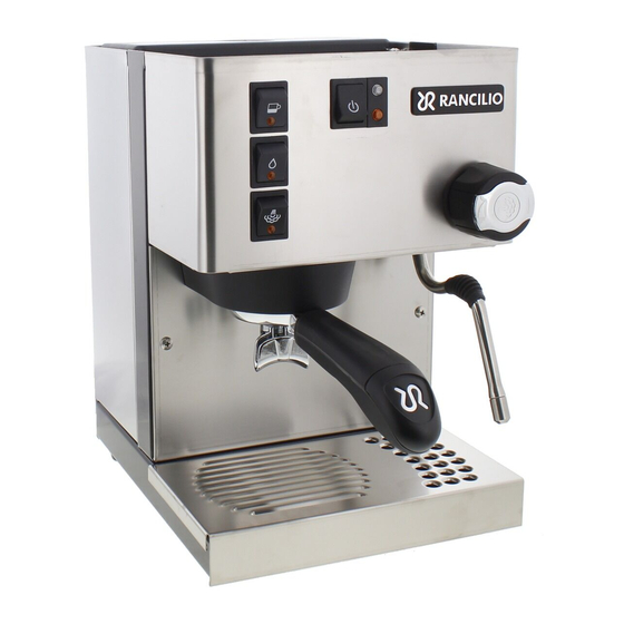
Rancilio Silvia E Supplemental Installation Manual
Hide thumbs
Also See for Silvia E:
- User manual ,
- Installation manual (21 pages) ,
- User manual (19 pages)
Advertisement
Supplemental Installation Guide for Silvia E
KIT‐RSRTDNb
(April 2016)
This is a supplemental guide for Rancilio Silvia E, released on the winter of 2015 for European market.
Since the changes of Silvia E are very limited from Silvia V4, this guide only cover the installation steps
that need to be adjusted due to these changes.
The only difference is that the tapping of power is different. The main power switch of the Silvia E has
changed from the original mechanical ON/OFF switch to a push button reset switch. Therefore, we have
to tap the power from the brew switch.
User should still use "KIT‐RSRTDN Installation guide V2.2" as the main installation guide.
1. Tapping the Power to the Controller
Replace the original brew thermostat with the RTDStat (pointed by the blue arrow in Figure 1). Then we
will tap two cables on the brew switch (pointed by green arrows in Figure 1) to supply power to the
controller. The green arrows point to a red and a black cable connected to the lower two blades on the
brew switch.
Figure 1. Cables need to be tapped are pointed by green arrows.
First, remove all four cables on the brew switch. Connect the two black cables with piggyback
connectors to the red and black cable removed from the brew switch.
Copyright 2007-2016, Auber Instruments Inc. All Rights Reserved.
No part of this manual shall be copied, reproduced, or transmitted in any way without the prior, written consent of Auber Instruments. Auber Instruments retains the exclusive rights to all information included in this
document.
Advertisement
Table of Contents

Summary of Contents for Rancilio Silvia E
- Page 1 Supplemental Installation Guide for Silvia E KIT‐RSRTDNb (April 2016) This is a supplemental guide for Rancilio Silvia E, released on the winter of 2015 for European market. Since the changes of Silvia E are very limited from Silvia V4, this guide only cover the installation steps that need to be adjusted due to these changes. The only difference is that the tapping of power is different. The main power switch of the Silvia E has changed from the original mechanical ON/OFF switch to a push button reset switch. Therefore, we have to tap the power from the brew switch. User should still use “KIT‐RSRTDN Installation guide V2.2” as the main installation guide. 1. Tapping the Power to the Controller Replace the original brew thermostat with the RTDStat (pointed by the blue arrow in Figure 1). Then we will tap two cables on the brew switch (pointed by green arrows in Figure 1) to supply power to the controller. The green arrows point to a red and a black cable connected to the lower two blades on the brew switch. Figure 1. Cables need to be tapped are pointed by green arrows. First, remove all four cables on the brew switch. Connect the two black cables with piggyback connectors to the red and black cable removed from the brew switch. Copyright 2007-2016, Auber Instruments Inc. All Rights Reserved. No part of this manual shall be copied, reproduced, or transmitted in any way without the prior, written consent of Auber Instruments. Auber Instruments retains the exclusive rights to all information included in this...
- Page 2 Next, put the piggyback connector on the red cable to the lower left blades of the brew switch. Put the other piggyback connector on the black cable to the lower right blade of the brew switch. Then put the orange cable back to its original position, which is the top left blade on the brew switch. Also put the white cable back to its original position, which is the top right blade on the brew switch. Please see Figure 4 and Figure 1 for reference. Figure 2. Connect piggyback connectors on black cables to the red and the black cables from the brew switch. Figure 3. Put the red and the black cable back to the brew switch. ...
- Page 3 Figure 4. Put the orange cable back to its original position on the brew switch. (End) Copyright 2007-2016, Auber Instruments Inc. All Rights Reserved. No part of this manual shall be copied, reproduced, or transmitted in any way without the prior, written consent of Auber Instruments. Auber Instruments retains the exclusive rights to all information included in this document.


Need help?
Do you have a question about the Silvia E and is the answer not in the manual?
Questions and answers