
Related Manuals for JETSURF ADVENTURE DFI PLUS


Summary of Contents for JETSURF ADVENTURE DFI PLUS
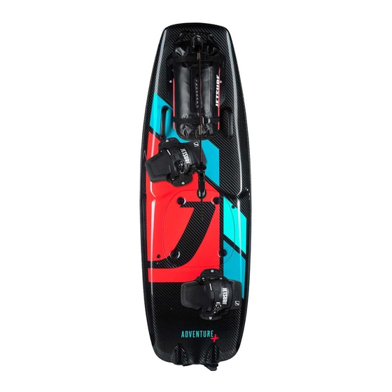
- Page 1 USER MANUAL version DFI005/EN_ADVENTURE PLUS_partB p a r t m o d e l ADVENTURE DFI PLUS...
-
Page 2: Symbol Used
SYMBOLS USED This symbol is used to mark important warnings which are often ignored by the JetSurf users. Please pay due attention to these warnings. You will thus avoid making frequent user mistakes. These warnings are based on the experience of the JetSurf servi- ce technicians. -
Page 3: Table Of Contents
ARRANGEMENT OF JETSURF AND IT’S ACCESSORIES IN BOARD BAG . . . . . . . . . . . . . . . . -
Page 4: Arrangement Of Jetsurf And It's Accessories In Board Bag
SAFETY MATTERS ARRANGEMENT OF JETSURF AND IT’S ACCESSORIES IN BOARD BAG Tool bag with accessories Screw for main fin - Allen Key M4 – Screw - PH 2x100 – Spark plug spanner – Mout. tool for check. spark plug – Spark plug –... -
Page 5: List Of Accessories
SAFETY MATTERS Stand - Disassemble a stand for travelling - For an assembled stand use a neoprene cover (Neoprene cover is part of the package) User manual part A and B, DOC (EU Declaration of Conformity) and Technical specification Rack Rotopax holder Rotopax fuel can (1 gallon - 3,79 l) -
Page 6: 1B Description
DESCRIPTION 1B DESCRIPTION Rack Grip Strap Padformator Engine compartment hood Indicator page 21 Engine cooling system output nozzle Bilge pump output Hood latch nozzle Silencer Side fin FCS Side fin FCS (right) (left) D F I 0 0 4 / E N _ A D V E N T U R E P L U S _ p a r t B... - Page 7 DESCRIPTION Throttle cable cord Control Handle page 15 Snorkel Throttle cable Side fin FCS Main fin remove for transport remove for transport Base Base Main fin Side fins FCS (left and right) D F I 0 0 4 / E N _ A D V E N T U R E P L U S _ p a r t B...
- Page 8 DESCRIPTION Engine MSR NG 100 DFI page 23 Electric bilge pump page 22 Alternator page 16 Jet pump EXHAUST page 14 D F I 0 0 4 / E N _ A D V E N T U R E P L U S _ p a r t B...
- Page 9 Ignition control unit (ICU) Engine starter (without a coil) page 17 page 18 Fuel tank page 12 Ignition coil Spark plug D F I 0 0 4 / E N _ A D V E N T U R E P L U S _ p a r t B...
- Page 10 DESCRIPTION ENGINE MSR NG 100 DFI Spark Plug Engine holder Fuel injector Main Gear Freewheel Countershaft Gear D F I 0 0 4 / E N _ A D V E N T U R E P L U S _ p a r t B...
- Page 11 DESCRIPTION Timing sensor Engine starter Throttle position sensor Throttle body Fuel line Throttle shaft control D F I 0 0 4 / E N _ A D V E N T U R E P L U S _ p a r t B...
-
Page 12: Fuel Tank
Fuel system consists of the fuel tank, a fuel filter (placed inside of fuel tank), fuel hoses and a fuel pump module. JetSurf™ has venting fuel ine fuel pump connector hose which leads from fuel tank up to the air intake in front part of the board. - Page 13 If you find an obvious damage or leak of the fuel tank or fuel system, DO NOT START – THE ENGINE! Immediately call the authorised dealer of JetSurf™ to assess the fault. Leaking fuel may cause serious damage to the environment and it could be a potential dangerous situation for people and assets.
-
Page 14: Exhaust
10 seconds outside of the water can result in damage which is not covered with the guarantee and damage of the exhaust system and other engine components. Even though the JetSurf™ engine produces much fewer side products during combustion than boat engines, exhaust fumes are still generated when the engine is running. These fumes are released by means of the exhaust system under the motorized power board where the carbon monoxide (CO) emissions are produced. -
Page 15: Control Handle
- Throttle cable ( m a r k e d 6 ) . The throttle trigger is situated on the handle, at the end of the throttle cable. JetSurf™ recommends controlling the throttle with your index finger. When the throttle trigger is pressed, you let more fuel in, when it is released, you let less fuel in. -
Page 16: Alternator
DESCRIPTION F I G U R E 1 F I G U R E 2 It is ABSOLUTELY NECESSARY for the rider to release the control han- dle when he/she loses full control over the board or his/her balance. By pulling the engine shut-off key from the engine shut-off switch you will stop the engine immediately - F I G U R E 1 a n d 2 . -
Page 17: Engine Starter
Please be aware that excessive use of the starter may results in its overheating and damage. NEVER START JETSURF IF YOU HAVE WATER IN THE ENGINE (DROWNED ENGINE). PIF THE ENGINE DOES NOT START AFTER THREE (3) ATTEMPTS, CHECK ALL THE BOARD ELEMENTS (HOSES, CONNECTIONS, CONNECTORS, SPARK PLUG...). -
Page 18: Ignition Control Unit (Icu)
Never try to charge the ignition control unit (ICU) using another charger different from the one specified by JetSurf™. This may result in which permanent dam. The motorized power board JetSurf™ is equipped with an ignition control NOTICE unit (ICU). - Page 19 ICU will switch over to the IDLE state. If the ICU remains in this state, water is sucked out of the in- ternal area of JetSurf by means of the electric bilge pump. The LED slowly flashes orange. RIDE If you place the key again to the switch, the ICU will switch over to the RIDE state.
- Page 20 SIGNALLING OF IGNITION CONTROL UNIT (ICU) FAULTS The errors are signalled by the indicator situated at the engine cover. The indicator is lit The ndicatot is not lit Course of signalling When the engine shut-off key was inserted in the handle for the first time, it stayed Fault type/cause in the handle for longer than 30 seconds.
-
Page 21: Indicator
1) Place the key to the indicator 2) To up the tank 3) Start the JetSurf by inserting the key in the control handle 4) When riding for the first 20 minutes, the indicator flashes green, then it flashes purple (there is approximately half tank of fuel) To use the indicator function again, repeat the procedure from item 1. -
Page 22: Electric Bilge Pump
Keep the suction filter clean. WARNING The bilge pump suck water from the internal area of JetSurf. It is a vital part for the JetSurf operation. During every ride, check whether the pump work properly. D F I 0 0 4 / E N _ A D V E N T U R E P L U S _ p a r t B... -
Page 23: Engine
Have the engine and the fuel WARNING system repaired by an authorised JetSurf™ seller before restarting the operation. Fuel must always be transported only in canisters approved by the D.O.T. -
Page 24: Specifications
SPECIFICATIONS 2B SPECIFICATIONS DESCRIPTION Overall length (mm) 1 800 Overall width (mm) Overall height (mm) Weight without pad (kg) Fuel tank capacity (l) Passenger capacity One operator Max Rider weight (kg) Category* Cruising range (mins) Max Speed 55 km/h (34 mph) CONSTRUCTION OF CRAFT Hull Carbon composite... - Page 25 A list of authorized dealers can be found on the website www.jetsurf.com D F I 0 0 4 / E N _ A D V E N T U R E P L U S _ p a r t B...
- Page 26 NOTE D F I 0 0 4 / E N _ A D V E N T U R E P L U S _ p a r t B...
- Page 28 .jetsurf .com...
Need help?
Do you have a question about the ADVENTURE DFI PLUS and is the answer not in the manual?
Questions and answers