Advertisement

Quick Links

5 3 2 3 H i g h w a y A v e n u e
J a c k s o n v i l l e , F L 3 2 2 5 4
T e l : ( 9 0 4 ) 5 0 3 - 9 7 3 3
F a x : ( 9 0 4 ) 5 0 3 - 9 7 1 9
w w w . r e v e r e s u r v i v a l . c o m
S e r v i c e Ma n u a l
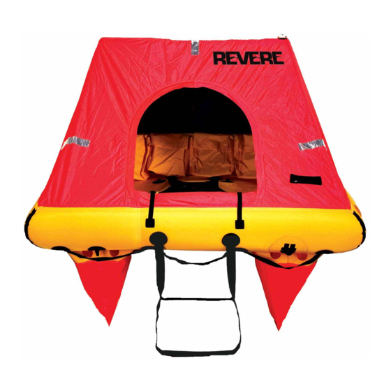
C o a s t a l E l i t e
A e r o E l i t e
O ff s h o r e E l i t e
Ma n u a l N u mb e r : 9 1 0 1
F o u r t h E d i t i o n

Advertisement

Table of Contents
loading
Need help?

Need help?

Do you have a question about the Coastal Elite and is the answer not in the manual?

Questions and answers

Summary of Contents for Revere Coastal Elite

  • Page 1 5 3 2 3 H i g h w a y A v e n u e J a c k s o n v i l l e , F L 3 2 2 5 4 T e l : ( 9 0 4 ) 5 0 3 - 9 7 3 3 F a x : ( 9 0 4 ) 5 0 3 - 9 7 1 9 w w w .
  • Page 3 DOCUMENTING A REVISION Record the Revision No. and Revision Date. Remove the old sheet and replace it with the revised copy. Record the Insert Date and then initial in the Inserted By column. Revisions made ONLY by Revere Survival Inc. INSERTED INSERTED REV.
  • Page 4 THIS PAGE INTENTIONALLY LEFT BLANK June 2/08 9101 RR - 2...
  • Page 5 Revere Survival Inc., Jacksonville, FL 32254 T. 904.503.9733 F. 904.503.9719 LETTER OF TRANSMITTAL 9101 Holders of Manual No. Offshore, Coastal, and Aero Elite Title: Service Manual Revision No.: Date: 10/21/2016 Signed: Date: 10/21/2016 Director of Technical Services Pages Affected Revision Highlights...
  • Page 7 SERVICE BULLETIN All service bulletins which are incorporated into this manual are required to be recorded in this list. All updates to this list will be made by the owner of the manual. SERVICE DATE OF DATE TITLE/DESCRIPTION REV. No. BULLETIN No.
  • Page 8 THIS PAGE INTENTIONALLY LEFT BLANK June 2/08 9101 SB - 2...
  • Page 9 Title: Revere Elite Liferafts - Protect crimps with heat-shrink sleeve to prevent corrosion. INTRODUCTION This service bulletin is to advise service stations how to protect crimps on Revere containers. A heat-shrink sleeve must be used to prevent discoloration and corrosion.
  • Page 10 7720 Philips Highway Jacksonville, FL 32256 (T) 904.786.0033 (F) 904.786.0890 SERVICE BULLETIN NO. 08/13 Warning: Use extreme care with the hot air gun. Allow sufficient time for parts to cool before handling directly. Air gun nozzle will remain hot after use. 3.4 With the heat gun at setting at HOT, apply heat evenly over the heat-shrink sleeve.
  • Page 11 7720 Philips Highway Jacksonville, FL 32256 (T) 904.786.0033 (F) 904.786.0890 SERVICE BULLETIN NO. 08/13 Figure 2 - Crimping Container Straps Figure 3 Figure 4 Fitting Heat-Shrink Sleeve Sealing Heat-Shrink Sleeve Feb 20/13 9101 SB - 3...
  • Page 12 7720 Philips Highway Jacksonville, FL 32256 (T) 904.786.0033 (F) 904.786.0890 SERVICE BULLETIN NO. 08/13 3.7 When the joint is completed correctly, the adhesive inside the sleeve will be observable at its cut edges, forming a seal with the strap. The finished joint should be positioned so that the sleeve does not directly contact the container - otherwise it may wear out from abrasion.
  • Page 13 (F) 904.786.0890 SERVICE BULLETIN NO. 08/13 TRANSMITTAL This page transmits the issue of the above numbered Revere Service Bulletin, which consists of this transmittal sheet plus four pages. Title: Revere Elite Liferafts - Protect crimps with heat-shrink sleeve to prevent corrosion.
  • Page 15 LIST OF EFFECTIVE PAGES PAGE PAGE PAGE TITLE ISSUE DATE PAGE TITLE ISSUE DATE Title Page Feb 20/13 June 2/08 June 2/08 Revision Record RR-1 Oct 21/16 2-10 Oct 21/16 RR-2 June 2/08 2-11 June 2/08 2-12 June 2/08 Service Bulletin SB-1 Feb 20/13 2-13...
  • Page 16 PAGE PAGE PAGE TITLE ISSUE DATE PAGE TITLE ISSUE DATE 4-10 July 13/11 Feb 20/13 4-11 Feb 20/13 June 2/08 4-12 July 13/11 Feb 20/13 4-13 June 2/08 Feb 20/13 4-14 June 2/08 7-10 June 2/08 4-15 July 13/11 7-11 June 2/08 4-16 June 2/08...
  • Page 17 PAGE PAGE ISSUE DATE PAGE TITLE ISSUE DATE 8-26 Oct 21/16 11-4 June 2/08 8-27 Oct 21/16 11-5 June 2/08 8-28 June 2/08 11-6 June 2/08 8-29 June 2/08 11-7 Feb 20/13 8-30 July 13/11 11-8 June 2/08 8-31 July 13/11 11-9 Oct 21/16 8-32...
  • Page 18 PAGE PAGE ISSUE DATE PAGE TITLE ISSUE DATE 12-3 Oct 21/16 12-4 Feb 20/13 12-5 Feb 20/13 12-6 Feb 20/13 12-7 Feb 20/13 12-8 Feb 20/13 12-9 Feb 20/13 12-10 Feb 20/13 12-11 Feb 20/13 12-12 Feb 20/13 12-13 Feb 20/13 12-14 Feb 20/13 12-16...
  • Page 19 LIST OF ASSOCIATED PUBLICATIONS None Listed June 2/08 9101 AP - 1...
  • Page 20 THIS PAGE INTENTIONALLY LEFT BLANK June 2/08 9101 AP - 2...
  • Page 21 LIST OF ABBREVIATIONS/SYMBOLS DEFINITION ABBREVIATION Degrees ° Percent Calories cal. Centigrade/Celcius Cubic Centimeter(s) Centimeter Centimeters of Mercury cm Hg Cubic Inch Farenheit Figure Fig. Fluid Ounce fl oz. Foot or Feet Gram Gram per Square Centimeter g/cm Inch (s) Inches of Mercury inHg Inside Diameter I.D.
  • Page 22 THIS PAGE INTENTIONALLY LEFT BLANK June 2/08 9101 AB - 2...
  • Page 23: Table Of Contents

    TABLE OF CONTENTS DESCRIPTION SECTION – PAGE No. Introduction Description, Data, and Operation Disassembly Testing and Fault Isolation Cleaning Service Inspection and Check Repair Assembly and Packing Storage Tools, Equipment, and Materials 10-1 Illustrated Parts List 11-1 Spare Parts 12-1 Appendix A Feb 20/13 9101...
  • Page 24 THIS PAGE IN INTENTIONALLY LEFT BLANK June 2/08 9101 TC - 2...
  • Page 25: Introduction

    INTRODUCTION General Manual Breakdown Shop Verification Warnings, Cautions, and Notes Layout of Manual List of Effective Pages Record of Revision Associated Publications June 2/08 9101 1 - 1...
  • Page 26 THIS PAGE INTENTIONALLY LEFT BLANK June 2/08 9101 1 - 2...
  • Page 27 Included in the manual are details of the procedures and information required to service only the Offshore and Coastal Elite liferafts and their associated equipment. It does not contain specific service instructions on products other than those manufactured by Revere Supply Company.
  • Page 28 List of Effective Pages The list of effective pages details all the pages that are contained in the manual and indicates the issue dates of those pages allowing the manual content to be checked for completeness and accuracy. This list is included in the preliminary pages of this manual. Record of Revision When required, the pages of this manual will be amended, approved, and re-issued as a revision.
  • Page 29: Description, Data, And Operation

    DESCRIPTION, DATA, AND OPERATION General Description Overview Detail 1. Standard Equipment 2. Inflation System Data Operation July 13/11 9101 2 - 1...
  • Page 30 THIS PAGE INTENTIONALLY LEFT BLANK June 2/08 9101 2 - 2...
  • Page 31: General

    GENERAL This section contains descriptive and operational information covering the Offshore Elite, Coastal Elite, and Aero Elite Liferafts. (See Figs. 1&2) The Elite liferafts’ self-inflation system is initiated manually. They are stored in either a container or a valise for rapid, easy access by passengers and crew in the event of an emergency.
  • Page 32 FIGURE 1 – COASTAL AND AERO ELITE Oct 21/16 9101 2 - 4...
  • Page 33 FIGURE 2 – OFFSHORE ELITE June 2/08 9101 2 - 5...
  • Page 34 THIS PAGE INTENTIONALLY LEFT BLANK June 2/08 9101 2 - 6...
  • Page 35: Description

    DESCRIPTION OVERVIEW Elite Liferafts are designed for coastal or offshore use and are available in 4, 6, and 8 person capacities. The Offshore Elite is composed of two large independent buoyancy tubes, a dual layer floor, an automatically erecting canopy, and a boarding ramp. The Coastal and Aero Elites are composed of one oversized buoyancy tube, a dual layer floor, an automatically erecting canopy, and a boarding ladder.
  • Page 36: Detail

    DETAIL Standard Equipment The Elite Liferafts are equipped with the following items and features (Figs. 1&2): Mooring Line This 20ft. (6.1m) line secures the raft to the vacuum bag, and is used for positioning the inflated raft for boarding. It has a breaking strength of up to 500lb. (227Kg.) (IPL Fig.
  • Page 37 10. Boarding Aids Boarding Ladder is available on the Coastal Elite only. Inflatable Boarding Ramp is available on the Offshore Elite only. Both the external Ladder and Ramp are positioned in front of the canopy door to allow for easy entrance into the raft.
  • Page 38: Inflation System

    (IPL Fig. 1, Items 40/50). Gas is delivered equally to both upper and lower buoyancy tubes on the Offshore Elite or both sub-compartments of the buoyancy tube on the Coastal Elite. Non-return transfer valves provide interconnection and damage control between the inflatable compartments of the buoyancy tube and the arch-tube.
  • Page 39 FIGURE 3 – VALISE AND CONTAINER June 2/08 9101 2 - 11...
  • Page 40 FIGURE 4 – INFLATION SYSTEM June 2/08 9101 2 - 12...
  • Page 41: Data

    DATA Inflation System Capacity Coastal and Aero 4,6,8, Offshore 4 4, 6, 8 Persons 327-176 Cylinder, DOT3AL2015, 176 cu. in. Color Offshore 6 Buoyancy tubes: Yellow 327-235 Boarding ramp: Yellow Cylinder, DOT3AL2216, 235 cu. in. Canopy: Orange Arch-tube: Yellow Offshore 8 Ballast bags: Yellow/Orange 327-282...
  • Page 42 L in. x W in. x H in. (canopy H) RAFT PART No. L in. x W in. x H in. (Kg.) (cm) (cm) Coastal Elite 4 31.5 x 22 x 12.5 74 x74 x 45.5 62 (28.15) 45-CE4C (80.01 x 55.88 x 31.75) (187.96 x 187.96 x 115.57)
  • Page 43 Torque settings for the 41045 inflation system. TORQUE SETTING, lbf ft COMPONENT (Nm) Inflation Valve to Cylinder 40-45 (54.25-61) Outlet Fitting 20-25 (27.10-33.90 Nm) Spring Retainer Cap 20-25 (27.10-33.90 Nm) Safety Disk Retainer 10-15 (13.50-20.34 Nm) Puncture Disk Retainer 10-15 (13.50-20.34 Nm) Syphon 5-10 (6.75-13.5 Nm) Fill Fitting Body...
  • Page 44 THIS PAGE INTENTIONALLY LEFT BLANK July 13/11 9101 2 - 16...
  • Page 45 OPERATION It is CRITICAL that the container is not thrown overboard without FIRST having been secured to a strong point on the ship. If this instruction is not observed, the container may be lost, and/or personnel may be pulled overboard with the container. Caution: DO NOT attempt to unpack and inflate the liferaft on deck;...
  • Page 46 FIGURE 5 - DEPLOYMENT July 13/11 9101 2 - 18...
  • Page 47: Disassembly

    DISASSEMBLY General Procedures June 2/08 9101 3 - 1...
  • Page 48 THIS PAGE INTENTIONALLY LEFT BLANK June 2/08 9101 3 - 2...
  • Page 49 GENERAL It will be necessary at normal service and overhaul periods (See Chapter 2 – Description, Data, and Operation) to remove the packed liferaft from the vessel. Ensure the working area is clean and dry, free from sharp projections, and large enough to fit the liferaft. The work surface should be smooth, preferably constructed of linoleum or PVC covering.
  • Page 50 THIS PAGE INTENTIONALLY LEFT BLANK June 2/08 9101 3 - 4...
  • Page 51 PROCEDURES Remove the packed liferaft in its valise/container from the vessel. Caution: Do not pull or jerk the painterline as this may cause operation of the inflation system. Inadvertent activation of the inflation system may cause personal injury or damage to raft components. Remove the liferaft from the valise/container as follows: Container Disconnect the taped painterline from the outside of the container.
  • Page 52 Remove tape untie Mooring Line from inside loop patch on vacuum bag. (See Detail A) Untie survival equipment pack, and place it aside for further inspection. (See Chapter 6, Inspection and Chapter 8, Assembly for further instructions on the equipment packs) When unpacking a raft from a valise ONLY, cut the nylon cord (IPL Fig.
  • Page 53 SAFETY PROCEDURE FOR CUTTING TENSIONED STRAP Warning: Wear eye, face, and hand protection. Keep work areas uncluttered and well lighted. Keep people at a safe distance. Stand to one side of the strap being cut and hold the strap against the package above the cutter. (See Fig.
  • Page 54 FIGURE 2 – REMOVAL FROM CONTAINER/VALISE June 2/08 9101 3 - 8...
  • Page 55 FIGURE 3 – DISCONNECTING THE PAINTERLINE June 2/08 9101 3 - 9...
  • Page 56 FIGURE 4 – REMOVAL FROM VACUUM BAG July 13/11 9101 3 - 10...
  • Page 57 FIGURE 5 – UNFOLD RAFT/DISENGAGE THE CYLINDER June 2/08 9101 3 - 11...
  • Page 58 THIS PAGE INTENTIONALLY LEFT BLANK June 2/08 9101 3 - 12...
  • Page 59: Testing And Fault Isolation

    TESTING AND FAULT ISOLATION General Test Record Chart Preparation Leakage Test Procedures - Coastal General Inflatable Chambers Leakage Test Procedures - Offshore General Inflatable Chambers Function Tests General Light Topping-Off Valves Pressure Relief Valves Inlet Check Valves Gas Cylinder and Inflation Valve Cylinder Valve Inflation Test Fault Isolation/Troubleshooting June 2/08...
  • Page 60 THIS PAGE INTENTIONALLY LEFT BLANK June 2/08 9101 4 - 2...
  • Page 61: General

    GENERAL This section contains instructions for minimum performance testing of the Coastal and Offshore Elite Liferafts. The performance test provides a functional equipment check to establish the ability of the systems and components to perform required design function or before the reinstallation of rafts removed from service.
  • Page 62 THIS PAGE INTENTIONALLY LEFT BLANK June 2/08 9101 4 - 4...
  • Page 63: Test Record Chart

    TEST RECORD CHARTS Keep records of ALL inflation tests. Make blank copies of this form and fill out charts when needed. LEAKAGE TEST RECORD – COASTAL ELITE LIFERAFT TYPE No. SERIAL No. INSPECTED BY: CHECKED BY: PACK LIFERAFTS WITHIN 48 HOURS OF TEST, UNLESS STORED UNDER APPROVED CONDITIONS...
  • Page 64 LEAKAGE TEST RECORD – OFFSHORE ELITE LIFERAFT TYPE No. SERIAL No. INSPECTED BY: CHECKED BY: PACK LIFERAFTS WITHIN 48 HOURS OF TEST, UNLESS STORED UNDER APPROVED CONDITIONS RE-TEST if not operationally packed within 30 days of test Date __________ Date __________ Time __________ corrected Time __________...
  • Page 65: Preparation

    PREPARATION Keep record of ALL inflation tests. Copies of Test Record Charts are provided in the previous section. Make blank copies and store at the end of the Section. Protect liferafts from draughts and direct sunlight as temperature affects pressure. Keep at hand a solution of mild liquid soap (NOT detergent) and water, and a plentiful supply of clean, dry, lint-free cloth.
  • Page 66 THIS PAGE INTENTIONALLY LEFT BLANK June 2/08 9101 4 - 8...
  • Page 67: Leakage Test Procedures - Coastal

    Each inflatable part of the main structure must be tested separately. All test results should be recorded on the Coastal Elite Test Record Chart (See Table A). The structure consists of all the chambers served by the gas inflation system. These include: •...
  • Page 68 Check the buoyancy chambers after 1 hour. Record the final tube pressure (Pf ), temperature tube ), time, and barometric pressure ( ) (See Table A). Calculate the corrected pressure ) if temperature and/or barometric pressure changes during the one hour test. (See corrected Table A for formula and Table C) If the change in the pressure of the tube is greater than 5% of the initial pressure, the liferaft has...
  • Page 69: Leakage Test Procedures - Offshore

    LEAKAGE TEST PROCEDURES - OFFSHORE GENERAL Each inflatable part of the main structure must be tested separately. All test results should be recorded on the Offshore Elite Test Record Chart (See Table B). The structure consists of all the chambers served by the gas inflation system. These include: •...
  • Page 70 Check the buoyancy chambers after 1 hour. Record the final tube pressure (Pf ), temperature tube ), time, and barometric pressure ( ) (See Table B). Calculate the corrected pressure ) if temperature and/or barometric pressure changes during the one hour test. (See corrected Table A for formula and Table C).
  • Page 71 Refer to Table C for correction quantities due to changes in barometric pressure or temperature over the test period. BUOYANCY TUBES - HIGH PRESSURE Change in Barometric Pressure, P (inHg) Raft Tube Pressure Correction (psi) -.30 -.1470 -.25 -.1225 -.20 -.0980 -.15 -.0735...
  • Page 72 BUOYANCY TUBES - HIGH PRESSURE Change in Temperature (°F) Raft Tube Pressure Correction (psi) -10° +.31 -9° +.28 -8° +.25 -7° +.22 -6° +.19 -5° +.16 -4° +.12 -3° +.09 -2° +.06 -1° +.03 0° +1° -.03 +2° -.06 +3° -.09 +4°...
  • Page 73 FIGURE 1- LEFT CHAMBER INFLATION (COASTAL) July 13/11 9101 4 - 15...
  • Page 74 FIGURE 3 – UPPER CHAMBER INFLATION (OFFSHORE) June 2/08 9101 4 - 16...
  • Page 75 FIGURE 5 – DIGITAL MANOMETER Feb 20/13 9101 4 - 17...
  • Page 76 THIS PAGE INTENTIONALLY LEFT BLANK June 2/08 9101 4 - 18...
  • Page 77 FUNCTION TESTS GENERAL A full function test is not required for normal service. The following items listed will need to be assessed for proper operation and restored if they are non-functional. Refer to Chapter 7 – Repair for repair/replacement instructions for failed components. LIGHT Check the unit expiration date.
  • Page 78 INLET CHECK VALVES Using clean, dry shop air, inflate the compartment to 2.0 psig. Spray a solution of soapy water on top of the valve. Apply solution slowly to generate the least amount of bubbles possible. Monitor and check for generation of new bubbles. The inlet check valves should be airtight and not allow new bubbles to form.
  • Page 79 CYLINDER VALVE INFLATION TEST Note: Do not perform the Cylinder Valve Inflation Test with the cylinder still attached to the raft. Remove cylinder from raft (See Chapter 3 – Disassembly). Install diffuser caps onto the inflation valve. Check the weight of the cylinder to make sure no leaks have occurred. Place cylinder into a vise and tighten down.
  • Page 80 FAULT ISOLATION The table below is given to facilitate the locations of troubles in the event of malfunction during the function test, their probable causes, and corrective action. In addition to using this table, visually check the liferaft and equipment for evidence of damage or signs of failure. Fault Probable Cause Corrective Action...
  • Page 81: Cleaning

    CLEANING General Procedures Liferafts Rigid Container Valise June 2/08 9101 5 - 1...
  • Page 82 THIS PAGE INTENTIONALLY LEFT BLANK June 2/08 9101 5 - 2...
  • Page 83 GENERAL This section contains instructions on cleaning the Elite Liferafts. When deemed necessary, periodic inspection and cleaning should be performed. The working area must be free from chemicals, corrosives, and solvents. Note: Only clean rafts if exceptionally dirty or absolutely necessary. CLEANING MATERIALS Caution: Use only cleaning agents used in Table A.
  • Page 84 THIS PAGE INTENTIONALLY LEFT BLANK June 2/08 9101 5 - 4...
  • Page 85 PROCEDURES Warning: All solvents: Flammable; Keep away from uncovered lights. Use solvents only in a well ventilated atmosphere. Do not splash into eyes and avoid breathing in the vapors. Use a barrier cream on hands and wash them after using solvents. Liferafts Wash the liferaft with a solution of mild liquid soap (Item 1) and water.
  • Page 86 THIS PAGE INTENTIONALLY LEFT BLANK June 2/08 9101 5 - 6...
  • Page 87: Service Inspection And Check

    SERVICE INSPECTION AND CHECK General Gas Inflation System Emergency Pack Valise/Container Pack June 2/08 9101 6 - 1...
  • Page 88 THIS PAGE INTENTIONALLY LEFT BLANK June 2/08 9101 6 - 2...
  • Page 89 GENERAL The liferaft is to be inspected every three (3) years to insure that the inflatable chambers will maintain the specified pressure, that the inflation system functions efficiently, and that all components and associated equipment are maintained in a serviceable condition. Replace the light at every three year inspection.
  • Page 90 THIS PAGE INITIALLY LEFT BLANK June 2/08 9101 6 - 4...
  • Page 91 GAS INFLATION SYSTEM Warning: The charged gas cylinder can become a lethal projectile if discharged to atmosphere when not fitted with a diffuser cap. Always fit diffuser caps to a cylinder valve outlet when handling a fully charged cylinder. Inspect hoses and non-return valves for visual defects and security. Weigh the cylinder and check it against the weight marked on the cylinder.
  • Page 92 THIS PAGE INTENTIONALLY LEFT BLANK June 2/08 9101 6 - 6...
  • Page 93 SURVIVAL EQUIPMENT PACKS Note: All items listed below may not by supplied in some survival equipment packs. For the full scale of contents, refer to the pack contents label. See IPL for component details. See Chapter 8 – Assembly for packing details. Caution: Ensure that the expiration date of certain items does not come due within the date of the next overhaul period.
  • Page 94 THIS PAGE INTENTIONALLY LEFT BLANK June 2/08 9101 6 - 8...
  • Page 95 VALISE/CONTAINER PACKS Valise Inspect valise for: Cleanliness, freedom from splits, tears, or other obvious signs of damage. Legibility of all marks and labels. Container Inspect container for: Cleanliness, freedom from cracks, voids, or other obvious signs of damage. Legibility of all marks and labels. June 2/08 9101 6 - 9...
  • Page 96 THIS PAGE INTENTIONALLY LEFT BLANK June 2/08 9101 6 - 10...
  • Page 97: Repair

    REPAIR General Non-Repairable Rafts Repairable Rafts Procedures Adhesive Mixing Instructions Preparation of Coasted Surfaces Applying Adhesive Repairing Torn Areas Patches Applying Patches Repair Limits for External Patches Component Repair Pressure Relief Valves Topping-Off Valves Inlet Check Valves Ramp Transfer Valve Arch Transfer Valve Inflation Valve Rigid Containers...
  • Page 98 THIS PAGE INTENTIONALLY LEFT BLANK June 2/08 9101 7 - 2...
  • Page 99: General

    Sewing repairs to the valise. If repairs beyond the limits of the conditions described in previous statements, it is recommended that the raft be returned to Revere Supply Co. Inc. Clean all repaired disassembled parts prior to re-assembly according to procedures described in the Cleaning Chapter of this manual.
  • Page 100 THIS PAGE INTENTIONALLY LEFT BLANK June 2/08 9101 7 - 4...
  • Page 101: Procedures

    (Part No. 95-306-001ADH) supplied in 16 oz. cans, and the accelerator (Part No. 95-306-001ACC) supplied in 1/2oz. bottles. Only the specified adhesive shall be used for the repair of liferafts manufactured by Revere Supply Company. Using unspecified adhesives may have unexpected side effects resulting in premature failures.
  • Page 102 PREPARATION OF COATED SURFACES Polyurethane-proofed surfaces Caution: VERY IMPORTANT – The heavy duty polyurethane coating on the material used for the buoyancy chambers/floor/arch-tubes must have the surface contamination completely removed by thoroughly cleaning the coated surfaces with solvent MEK (Methyl Ethyl Ketone). Petroleum or Toluene type cleaning solvents are ineffective on this material and must not be used.
  • Page 103: Applying Adhesive

    APPLYING ADHESIVE Combine the adhesive with the appropriate amount of accelerator and mix until uniform. The catalyzed system has a pot life of 8 hours. Both the tube fabric surface and the patch fabric, shall have three (3) coats of adhesive applied with a stiff brush in such a manner that the adhesive is driven firmly into the fabric weave.
  • Page 104: Repairing Torn Areas

    Careful attention is to be given when rolling down seams and patches, particularly on curved edges. Puckers and channels must be avoided, and all seams MUST be rolled twice. Caution: Solvents must not be used for removing surplus adhesive from repair areas.
  • Page 105: Repair Limits For External Patches

    Revere Supply Company cannot offer partial or complete panel/tube replacement. It will be necessary to replace the liferaft should significant damage occur to the panels or tubes. Repair Limits for External Patches Patching of the buoyancy tubes is permitted, but there must not be more than 10 patches per panel, and the area of the 10 patches together must not exceed 25% of the panel area.
  • Page 106: Component Repair

    COMPONENT REPAIR Pressure Release Valve Dismantling the pressure relief valve is not permitted. Unscrew the valve and replace. Topping-Off Valve Unscrew the valve and replace. Inlet Check Valves Unscrew the valves and replace. Ramp Transfer Valve (Offshore Elite only) Not replaceable. Arch-Tube Valve Not replaceable.
  • Page 107: Gelcoat

    Gelcoat This is the outer surface of the container. Damage to the gelcoat does not affect the GRP, although it may expose it to view. Where only the gelcoat is damaged, repair with a GRP filler, such as Isopon, and proceed as follows: Clean the damaged area with acetone to remove all contamination.
  • Page 108: Repair Limits

    Repair Limit The limits of repair are: Holes or penetrating damage (i.e. through the glass fiber mat) over an area of more than 12in (77cm )on the outer surface of the container Holes or penetrating damage over an area of more than 9in (58cm ) on the inner surface of the container...
  • Page 109 FIGURE 1 – PATCHES AND TAPE APPLICATION June 2/08 9101 7 - 13...
  • Page 110 FIGURE 2 – PATCH APPLICATION OVER SEAM July 13/11 9101 7 - 14...
  • Page 111 Keep records of all repairs. Make blank copies of this form and fill out charts when needed. REPAIR RECORD LIFERAFT TYPE No. SERIAL No. REPAIRS REQUIRED PART DAMAGE FORM OF REPAIR INSP. BY Upper Buoyancy Tube Lower Buoyancy Tube* Arch-Tube Floor Boarding Ramp* Canopy...
  • Page 112 THIS PAGE INTENTIONALLY LEFT BLANK June 2/08 9101 7 - 16...
  • Page 113: Assembly And Packing

    ASSEMBLY AND PACKING General Component Setup A. Sea Anchor B. Rescue Line C. Painterline D. Light E. Knife F. Container G. Survival Equipment Pack Inflation Valve Disassembly & Rebuilding Process Packing Procedure June 2/08 9101 8 - 1...
  • Page 114 THIS PAGE INTENTIONALLY LEFT BLANK June 2/08 9101 8 - 2...
  • Page 115 GENERAL This section describes the proper procedures for assembly and repacking of all Elite life rafts. Before beginning the assembly, the work area must be clean, dry, and free from sharp projections. Work should be done on a smooth surface, preferably linoleum. Throughout preparation and packing of the liferaft and its associated equipment, all ties are to be bowlines unless stated otherwise, and are to be taped over with 1in.
  • Page 116 THIS PAGE INTENTIONALLY LEFT BLANK June 2/08 9101 8 - 4...
  • Page 117 COMPONENT SETUP COMPONENT PREPARATION Ensure the canopy door is fully opened and the rear window is fully closed. Warning: Take care when using any electric tooling. Be sure to protect your eyes and hands when performing any of these procedures. Refer to tool manufacturer’s manuals on proper use of their equipment before performing any of these outlined procedures.
  • Page 118 Container Setup Reference Fig. 3 for cutout and hole locations in the top and bottom containers. Position the top container shell (IPL Fig. 4, Items 10/10A) so the inside is visible. Place foam strip (IPL Fig. 4, Item 60) flat along raised edge of top container shell to form a gasket seal when the container is shut.
  • Page 119 FIGURE 2A – SEA ANCHOR PREPARATION FIGURE 2B – STOWING PAINTERLINE June 2/08 9101 8 - 7...
  • Page 120 FIGURE 3 – CONTAINER SPECIFICATIONS June 2/08 9101 8 - 8...
  • Page 121 FIGURE 4A – SURVIVAL PACK COMPONENTS TIPS! Seasick pills should be inserted  lengthwise underneath the food rations. Fold corners of food rations so they don’t  puncture bag Store fishing kit under first aid kit.  Store paddles under parachute rockets ...
  • Page 122 FIGURE 4B – 120in. TIE LINE CONNECTION July 13/11 9101 8 - 10...
  • Page 123 INFLATION VALVE DISASSEMBLY & REBUILDING PROCESS 41045 Inflation Valve 1.1 Torque Settings 1.2 Removal of Inflation Valve from Cylinder 1.3 41045 Disassembly / Rebuilding 1.4 41045 Reassembly / Rebuilding 1.5 Inflation Valve Installation 1.6 Charging Cylinder Refer to Section 11 - Illustrated Parts List Figure 3 for breakdown of Inflation Valve 41045 components.
  • Page 124 1.1 Torque Settings The settings listed in table below list the required torque settings for the 41045 Series inflation system. Refer to this table when tightening inflation system components that require a specific setting. Tighten to the minimum setting in the specified range first. If leakage occurs, discharge the assembly and tighten to the maximum setting.
  • Page 125 1.3.2 Inflation Valve Illustrated Disassembly / Rebuilding Process Note: There are three cut-outs in the securing fixture with only one cut-out to accommodate sockets. All components can be removed using a socket wrench, but most will only require a standard or open-ended wrench. If using a socket (A 6pt socket is recommended to minimize dings to the hex edges), rotate the fitting to be removed to this cut-out.
  • Page 126 Step 5: Remove the Fill Fitting Body (IPL Fig. 3, Item 70). Step 6: Remove the Fill Fitting Poppet (IPL Fig. 3, Item 50) from Fill Fitting Body. Step 7: Using a socket wrench, remove the Safety Disk Retainer (IPL Fig. 3, Item 110). Step 8: Remove the Spring Retainer Cap (IPL Fig.
  • Page 127 Step 9: Remove the Spring (IPL Fig. 3, Item 170)., Pull Lanyard (IPL Fig. 3, Item 190)., and Bayonet (IPL Fig. 3, Item 160). The bayonet may be difficult to remove. Use the bayonet removal tool (Part No. 41130-101) or similar 0.48in. I.D. piece of plastic tubing.
  • Page 128 1.4 Inflation Valve Reassembly 1.4.1 Only organizations that are equipped with the latest technical data, tools and fixtures are permitted to perform inflation valve rebuilding activities. Reassembly Process. 1.4.2 Steps 1-12 show a pictorial representation of the Inflation Valve 1.4.3 All O-rings, Safety Rupture Disk, Puncture Disk, Puncture Pin and Spring are replaced every six years.
  • Page 129 1.4.2 Inflation Valve Illustrated Reassembly / Rebuilding Process Step 1: Prepare the Inflation Valve for rebuilding. Items List:  Rebuild Kit (Part No. 95-41046-101)  DC 55 O-Ring Lubricant  Wrenches and Sockets  Torque Wrench Step 2: After applying a light coat of DC-55 lubricant to the O-rings, install the O-rings on the Valve Body, Bayonet, Caps, Puncture Disk Retainer, and Safety Disk Retainer as necessary.
  • Page 130 Step 4: Place valve in securing fixture (Part No. 95- 338-014). After applying a light coat of DC-55 lubricant to the Puncture Disk (IPL Fig. 3, Item 100). install it and the Puncture Disk Retainer (IPL Fig. 3, Item 130). Repeat with the Safety Disk (IPL Fig.
  • Page 131 Step 9: Install Outlet Fittings. Step 10: Torque all components to the settings listed in the table. Step 11: Apply a thin layer of DC-55 lubricant to the syphon tube O-Ring before installing on valve. Step 12: Attach syphon tube to Inflation Valve Body and torque according to setting listed in the table.
  • Page 132 1.5 Inflation Valve Installation Inflation Valve Installation 1.5.1 Inspect inflation valve threads for cleanliness and damage. 1.5.2 Inspect cylinder threads and O-ring Groove for cleanliness and damage. Carefully screw Inflation Valve into Cylinder. No binding or interference should be encountered until O- ring enters the O-ring groove on the top 1.5.3 Apply a thin film of DC-111 lubricant to inflation valve O-ring.
  • Page 133 1.6 Charging the Cylinder 1.6.1 The inflation system is charged with a combination of Carbon Dioxide and Nitrogen. Cylinders must only be charged by properly trained technicians. 1.6.2 Verify proper installation of Inflation Valve, install Diffuser Caps on outlet connectors. 1.6.3 Remove Fill Fitting Cap.
  • Page 134 1.6.7 When complete, remove charge adaptor and install cap and torque per value in torque table. Cylinder charge weights WT. LBS WT. LBS RAFT MODEL (kg) (kg) Coastal/Aero Elite 4 2.64 to 2.70 (1.20 to 1.22) .12 to .14 (.055 to .065) Coastal/Aero Elite 6 3.10 to 3.16 (1.41 to 1.43) .15 to .17 (.065 to .075)
  • Page 135 PACKING PROCEDURE Note: It is recommended that packing the liferaft be performed by at least two men. Place the liferaft on a platform or in an open area with enough room to maneuver the liferaft and container/valise during packing. Locate the topping-off (inflate/deflate) valves. (Coastal Elites will have 4 while the Offshore Elites will have 5).
  • Page 136 Spread out the liferaft on the packing surface (See Fig. 8A - Folding Diagrams). Start by folding up the boarding ramp, if applicable. Continue folding the raft from the right side being sure to get the fold crease as close to the cylinder valve as possible. Fold as tight as possible to top of cylinder valve.
  • Page 137 14. Position raft so inflation valve pull cable loop and threaded outlet protrudes through the small round hole in the vacuum bag. Replace vacuum washer and vacuum retainer over pull cable loop being sure the vacuum washer is positioned so the flange side of the washer is secure against the bag.
  • Page 138 26. After making sure all vacuum bag corners are contained within the valise, shut the valise by mating all velcro strips together. 27. Place completed inspection sticker on valise. (See Section 2 - Description Fig. 3) Packing into Container 19. Locate the bottom container shell and place it on the floor of the working area. 20.
  • Page 139 26. Put two ratchet straps (Part No. 40-05654009) around the container, making sure the straps do not cover the grooves in the container. Tighten the ratchet straps uniformly around the container. Make sure the upper half of the container mates with the lower half of the container correctly. (See Fig.
  • Page 140 FIGURE 5 – TOPPING-OFF (INFLATE/DEFLATE) VALVE July 13/11 9101 8 - 28...
  • Page 141 FIGURE 7 – STOWAGE OF COMPONENTS June 2/08 9101 8 - 29...
  • Page 142 FIGURE 8A – FOLDING DIAGRAM STEP 1 Note: Refer to Section 2 – Description, Tables A & B for the L x W x H dimensions shown in the following folding diagrams. July 13/11 9101 8 - 30...
  • Page 143 FIGURE 8B – FOLDING DIAGRAM STEP 2 July 13/11 9101 8 - 31...
  • Page 144 FIGURE 8C – FOLDING DIAGRAM STEP 3 July 13/11 9101 8 - 32...
  • Page 145 FIGURE 8D – FOLDING DIAGRAM STEP 4 Lengthwise folds vary depending on the type of liferaft being packed. Folds for Coastal Elite liferafts should be loose, while folds for Offshore Elites should be tight. Rafts fitting into a container or a 4 person valise will be folded 3 times along the length of the raft, while 6 and 8 person valise rafts will be folded four times.
  • Page 146 FIGURE 8E – FOLDING DIAGRAM STEP 5 Feb 20/13 9101 8 - 34...
  • Page 147 FIGURE 8F – FOLDING DIAGRAM STEP 6 July 13/11 9101 8 - 35...
  • Page 148 FIGURE 8G – FOLDING DIAGRAM STEPS 7 & 8 July 13/11 9101 8 - 36...
  • Page 149 FIGURE 9 – BURST STRAP ATTACHMENT July 13/11 9101 8 - 37...
  • Page 150 FIGURE 10 – GASKET REMOVAL July 13/11 9101 8 - 38...
  • Page 151 FIGURE 12 – ATTACHMENT OF MOORING/PAINTERLINES July 13/11 9101 8 - 39...
  • Page 152 FIGURE 14 – SEALING BAG July 13/11 9101 8 - 40...
  • Page 153 FIGURE 15A – PLACING BAG IN VALISE July 13/11 9101 8 - 41...
  • Page 154 FIGURE 16 – INFLATION VAVE/PAINTERLINE CONNECTION June 2/08 9101 8 - 42...
  • Page 155 FIGURE 18 – CONTAINER STRAPS FIGURE 19 – HEAT-SHRINK SLEEVES Feb 20/13 9101 8 - 43...
  • Page 156 FIGURE 20 – TAPE FOR STRAPS AND PAINTERLINE Feb 20/13 9101 8 - 44...
  • Page 157 STORAGE General June 2/08 9101 9 - 1...
  • Page 158 THIS PAGE INTENTIONALLY LEFT BLANK June 2/08 9101 9 - 2...
  • Page 159 GENERAL This section describes the proper storage procedures for all Elite life rafts. Rafts packed in fabric valises should be stowed where they can be easily reached in an emergency. Valise packed rafts can be kept on deck for short periods of time only but should be stowed in a location where they are not continuously exposed to direct sunlight, weather, or water spray.
  • Page 160 THIS PAGE INTENTIONALLY LEFT BLANK June 2/08 9101 9 - 4...
  • Page 161 TOOL, EQUIPMENT, AND MATERIALS General Tool List Feb 20/13 9101 10 - 1...
  • Page 162 THIS PAGE INTENTIONALLY LEFT BLANK June 2/08 9101 10 - 2...
  • Page 163: Spare Parts

    GENERAL This section contains a listing of all tools, equipment, and materials used to service the Coastal and Offshore Elite liferafts. Images of all the tools can be found in Chapter 12 - Spare Parts. To keep your tools in proper working order, take care of them by: •...
  • Page 164 THIS PAGE INTENTIONALLY LEFT BLANK June 2/08 9101 10 - 4...
  • Page 165 TOOL LIST TOOL/EQUIPMENT/MATERIAL PART NUMBER SECTION 3 – DISASSEMBLY Scissors Wrench Torque Spanner Wrench – Vacuum Bag Valve Retainer 45-338-009 Diffuser Cap, -4 (Aluminum) 95-301-018 Diffuser Cap, -5 (Brass) 95-301-017 SECTION 4 – TESTING AND FAULT ISOLATION Digital Manometer Thermometer (hang on manometer) Rubber Tubing (1/8in.
  • Page 166 TOOL/EQUIPMENT/MATERIAL PART NUMBER Steel Hand Roller 80-338-003 Scissors Solution Brushes a. 1/2in. wide (12mm wide) b. 1in. wide (25mm wide) c. 1 1/2in. wide (38mm wide) Adhesive System, Polyurethane, 2 part a. Adhesive 95-306-001ADH b. Accelerator 95-306-001ACC Methyl Ethyl Ketone (MEK) White Epimide or White Polyurethane paint Lint-free fabric pad Lint-free cloth, clean and dry...
  • Page 167 TOOL LIST Painterline Clear Plastic Sheet Torque Wrenches (0-50 lbf. in., 0-50 lbf. ft.) Diffuser Cap, -4 (Aluminum) 95-301-018 Diffuser Cap, -5 (Brass) 95-301-017 Valve Charging Stem (Quick Connect) 40-338-005 Valve Charging Body (Quick Connect) 40-338-006 Bleed Down Tool 40-338-007 Puncture Disc Retaining Tool 95-338-010 Socket 1-3/8in.
  • Page 168 THIS PAGE INTENTIONALLY LEFT BLANK Feb 20/13 9101 10 - 8...
  • Page 169 ILLUSTRATED PARTS LIST (IPL) Introduction Numerical Parts List Detailed Parts List Image List June 2/08 9101 11 - 1...
  • Page 170 THIS PAGE INTENTIONALLY LEFT BLANK June 2/08 9101 11 - 2...
  • Page 171 Items with the same part number but different quantities per assembly will be assigned a suffix as a variant of the original part number, e.g. 10 and 10A. PART NUMBERING Revere Supply Company part number. ILLUSTRATIONS A view of each assembly, exploded as necessary to show the component parts is provided. Each illustration is assigned a figure number.
  • Page 172 NOMENCLATURE CONTINUED ‘Replaced By’ means that the part in the part number column is replaced by and is interchangeable with the part number shown in the notation. ‘Replaces’ means that the part in the part number column replaces and is interchangeable with the part number shown in the notation.
  • Page 173 Image List at the end of this section. 10. VENDOR CODES AND ADDRESSES A part manufactured by a different company other than Revere Supply is identified by a Vendor Code, following the nomenclature. Vendor Codes are in accordance with the Federal Supply Codes for Manufacturers for American Vendors, and NATO Codes for UK Vendors.
  • Page 174 THIS PAGE INTENTIONALLY LEFT BLANK June 2/08 9101 11 - 6...
  • Page 175 NUMERICAL PARTS LIST No equivalent substitutes are to be used for listed items without the prior written consent of Revere Supply Company. Revere Supply Company will not accept responsibility for any equipment malfunction where unauthorized substitutions have been used. The Numerical Index is an alpha-numeric list of all part numbers included in the Detailed Parts List.
  • Page 176 THIS PAGE INTENTIONALLY LEFT BLANK June 2/08 9101 11 - 8...
  • Page 177 FIG – ITEM No. PART No. UNITS PER ASSY. 10-TAPE-1 1-190 10-79-001A 1-200 10-7524 5-150 30-50672 5-20 5-10 30-52900 5-10A 40-REV169 4-60 40-05720019 5-90 40-05720023 5-100 40-08304 5-190 40-15372001 1-180 40-20883001 4-70 40-40318001 5-80 40-45510001 1-220 40-45932001 1-230 40-50450001 1-280 40-54051 5-180 41030-4...
  • Page 178 FIG – ITEM No. PART No. UNITS PER ASSY. 45-CE6C 1-1C 45-CE8V 1-1D 45-CE8C 1-1E 45-OE4V 1-1F 45-OE4C 1-1G 45-OE6V 1-1H 45-OE8C 1-1J 45-OE8V 1-1K 45-OE6C 1-1L 45-41188-1 1-80B 50-REVRN4 5-140 50-REV3002-1 4-80 80-KNIFELOGO 1-210 80-900 5-170 5-110 81-60-0900 5-110A 5-110B 5-130 90-SO-FB400/REV...
  • Page 179 FIG – ITEM No. PART No. UNITS PER ASSY. 1-20 95-41044-101 1-20A 95-41044-103 2-1A 1-20B 95-41044-105 2-1B 1-20C 95-41044-107 2-1C 1-20D 95-41044-109 2-1D 1-20E 95-41044-111 2-1E 1-20F 95-41044-113 2-1F 1-20G 95-41044-115 2-1G 95-41045-1 3-10 95-41045-2 3-20 95-41045-3 3-30 95-41045-4 3-40 95-41045-5 3-50 95-41045-6...
  • Page 180 FIG – ITEM No. PART No. UNITS PER ASSY. 95-41050-101 1-70 95-41050-103 1-70A 95-41050-105 1-70B 95-41050-107 1-70C 95-41050-109 1-70D 95-41050-111 1-70E 95-41050-113 1-70F 95-41050-115 1-70G 95-41050-117 1-70H 95-41059-20 5-220 1-90 95-41059-101 1-90A 95-41059-103 5-1A 1-90B 95-41059-105 5-1B 1-90C 95-41059-107 5-1C 1-90D 95-41059-109 5-1D...
  • Page 181 DETAILED PARTS LIST No equivalent substitutes are to be used for listed items without the prior written consent of Revere Supply Company. Revere Supply Company will not accept responsibility for any equipment malfunction where unauthorized substitutions have been used. Feb 20/13...
  • Page 182 Feb 20/13 9101 11 - 14...
  • Page 183 FIG. No. EFF. IMAGE PART No. NOMENCLATURE ITEM CODE ASSY. Fig. 1 –1 45-CE4V Life Raft, Coastal Elite 4 Valise Pack –1A 45-CE4C Life Raft, Coastal Elite 4 Container Pack –1B 45-CE6V Life Raft, Coastal Elite 6 Valise Pack –1C...
  • Page 184 NOMENCLATURE ITEM CODE ASSY. Fig. 1  95-41044-107 Cylinder & Valve Assy. Coastal Elite 4 (See Fig. 2) (Superseded by 20F) Do not reinstall  95-41044-109 Cylinder & Valve Assy. Coastal Elite 6 (See Fig. 2)  95-41044-111 Cylinder & Valve Assy.
  • Page 185 UNITS FIG. No. EFF. IMAGE PART No. NOMENCLATURE ITEM CODE ASSY.  95-41059-109 Survival Equipment Pack Coastal/Aero Elite 6 (See Fig. 5 for breakdown)  95-41059-111 Survival Equipment Pack Coastal/Aero Elite 8 (See Fig. 5 for breakdown)  95-41042-10 Mooring Line, 20 ft. ABCDEF 95-41040-10 ...
  • Page 186 FIGURE 2 – CYLINDER & VALVE ASSEMBLY June 2/08 9101 11 - 18...
  • Page 187 Cylinder & Valve Assy. (CO Coastal/Aero Elite 6 –1E 95-41044-111 Cylinder & Valve Assy. (CO Coastal/Aero Elite 8 –1F 95-41044-113 Cylinder & Valve Assy. (CO Coastal Elite 4 (Supersedes 1C) –1G 95-41044-115 Cylinder & Valve Assy. (CO Offshore Elite 6 (Supersedes 1A)  95-41045-101...
  • Page 188 FIGURE 3 – INFLATION VALVE ASSEMBLY June 2/08 9101 11 - 20...
  • Page 189 UNITS FIG. No. EFF. IMAGE PART No. NOMENCLATURE ITEM CODE ASSY. Fig. 3 95-41045-101 Inflation Valve, Model 41045 95-41046-101 Valve Overhaul Kit 95-41045-1  Body Assembly 95-41045-2  I.D. Decal 95-41045-3  O-Ring (-210)* 95-41045-4  O-Ring (006)* 95-41045-5  Fill Fitting Poppet 95-41045-6 ...
  • Page 190 FIGURE 4 – CONTAINER ASSEMBLY July 13/11 9101 11 - 22...
  • Page 191 UNITS FIG. No. EFF. IMAGE PART No. NOMENCLATURE ITEM CODE ASSY. Fig. 4 41052-101 Container Assy., Small 41054-101 Container Assy., Large 41053-1  Container Shell, Small, Top 41055-1  Container Shell, Large, Top 41053-2  Container Shell, Small, Bottom 41055-2 ...
  • Page 192 FIGURE 5 – SURVIVAL EQUIPMENT PACK Please refer to Image List for component visuals. June 2/08 9101 11 - 24...
  • Page 193 SURVIVAL EQUIPMENT PACK CHART UNITS FIG. No. EFF. IMAGE PART No. NOMENCLATURE ITEM CODE ASSY. Fig. 5 –1 41059-101 Pack, Survival Equipment Offshore Elite 4 –1A 41059-103 Pack, Survival Equipment Offshore Elite 6 –1B 41059-105 Pack, Survival Equipment Offshore Elite 8 –1C 41059-107 Pack, Survival Equipment...
  • Page 194 UNITS FIG. No. EFF. IMAGE PART No. NOMENCLATURE ITEM CODE ASSY. Fig. 5  40-54051 Sponges  40-08304 Scissors  95-301-001 Handpump Owner’s Manual  95-41080-1SH  95-41059-20 Tie Line, 120in.  95-41078-1 Placard, Survival Equipment Pack  95-41077-101 Bag Assy. Survival Kit Feb 20/13 9101 11 - 26...
  • Page 195 IMAGE LIST ITEM # 1 Topping Off Valve Part # 95-326-003 FIG-ITEM QTY. 1-30 1-30A ITEM # 2 Fixed Inlet Check, -5 Female Part # 95-325-002 FIG-ITEM QTY. 1-40 ITEM # 3 Rotating Inlet Check w/ Hose Part # 95-325-003 FIG-ITEM QTY.
  • Page 196 ITEM # 5 Label, Elite Logo, Container Part # 42-41068-1 FIG-ITEM QTY. 4-30 ITEM # 6 Label, Inflation, Container Part # 42-41069-1 FIG-ITEM QTY. 4-40 ITEM # 7 Card, Elite Data Panel, Container Part # 42-41070-1 Card, Elite Data Panel, Valise Part # 42-41071-1 FIG-ITEM QTY.
  • Page 197 ITEM # 9 Vacuum Bag Assembly Part # 95-41143-101 FIG-ITEM QTY. 1-150 ITEM # 10 Owner’s Manual, Elite Rafts, Book Part # 95-41080-1BK FIG-ITEM QTY. ITEM # 11 Light, L6 Part # 10-79-001A FIG-ITEM QTY. 1-200 ITEM # 12 Knife, Floating Part # 80-KNIFELOGO FIG-ITEM QTY.
  • Page 198 ITEM # 13 Inflation Valve, Model 41045 Part # 95-41045-101 FIG-ITEM QTY. 2-10 ITEM # 14 Handflare, Red Part # 30-52900 FIG-ITEM QTY. 5-10 5-10A ITEM # 15 Parachute Signal Rocket, Red Part # 30-50672 FIG-ITEM QTY. 5-20 ITEM # 16 Bailer Part # 95-41065-101 FIG-ITEM...
  • Page 199 ITEM # 17 Signal Mirror Part # 95-51119-101 FIG-ITEM QTY. 5-40 ITEM # 18 Paddle Part # 95-301-019 FIG-ITEM QTY. 5-50 ITEM # 19 Fishing Kit Part # 95-301-061 FIG-ITEM QTY. 5-60 ITEM # 20 Repair Kit Part # 95-41142-101 Small Plug: 40-40318001 Medium Plug: 40-05720019 Large Plug: 40-05720023...
  • Page 200 ITEM # 21 Seasick Tablets (2 pills/pkg.) Part # 81-60-0900 FIG-ITEM QTY. 5-110 5-110A 5-110B ITEM # 22 Drinking Water (4.23oz./pkg.) Part # 90-SO-WA442PK FIG-ITEM QTY. 5-120 5-120A 5-120B ITEM # 23 Food Rations (400 cal./pkg.) Part # 90-SO-FB400/REV FIG-ITEM QTY.
  • Page 201 ITEM # 25 First Aid Kit Part # 95-51120-101 Expiration of Components: Check every 3 years FIG-ITEM QTY. 5-160 ITEM # 26 Whistle and Lanyard Assembly Part # 80-900 FIG-ITEM QTY. 5-170 ITEM # 27 Sponge Part # 40-54051 FIG-ITEM QTY.
  • Page 202 ITEM # 29 Handpump Part # 95-301-001 FIG-ITEM QTY. 5-200 ITEM # 30 Owner’s Manual Part # 95-41080-1SH FIG-ITEM QTY. 5-210 ITEM # 31 Placard, Survival Equipment Pack Part # 95-41078-1 FIG-ITEM QTY. 5-230 ITEM # 32 AA Batteries Part # 10-7520 Expiration: 3 years FIG-ITEM QTY.
  • Page 203 ITEM # 33 Valve Overhaul Kit (for Model 41045) Part # 95-41046-101 FIG-ITEM QTY. 3-1A ITEM #34 Card, Aero Elite Data Panel, Valise Part # 45-41188-1 FIG-ITEM QTY. 1-80B ITEM #35 ITEM #36 Oct 21/16 9101 11 - 35...
  • Page 204 THIS PAGE INTENTIONALLY LEFT BLANK Feb 20/13 9101 11 - 36...
  • Page 205 SPARE PARTS LIST Introduction Image List Tool Image List Feb 20/13 9101 12 - 1...
  • Page 206 THIS PAGE INTENTIONALLY LEFT BLANK Feb 20/13 9101 12 - 2...
  • Page 207 This section provides an illustrated parts breakdown for the purpose of ordering replacement parts. It should not be used for any other purpose. An image of each part is provided. Each image has a corresponding Revere Supply Company part number and description of the item.
  • Page 208 THIS PAGE INTENTIONALLY LEFT BLANK Feb 20/13 9101 12 - 4...
  • Page 209 IMAGE LIST Description Part Number Vinyl Tape 1, White 10-TAPE-1 Gaffers Tape 4, Black 10-TAPE-4 Raft Tube Fabric 10-302-012 (Yellow) Feb 20/13 9101 12 - 5...
  • Page 210 Description Part Number Canopy Fabric 10-302-013 (Orange) Battery, AA, 1.5V 10-7524 L6 Light 10-79-001A Para Rocket, Red 30-50672 Feb 20/13 9101 12 - 6...
  • Page 211 Description Part Number Hand Flare, Red 30-52900 Painterline Sachet 36-43007-101 Assembly 40-LPCOAST-B (Coastal Elite, 4,6,8) (Offshore Elite 4) Container, Elite, Bottom 40-LP1-B (Offshore Elite 6,8) 40-LPCOAST-T (Coastal Elite, 4,6,8) (Offshore Elite 4) Container, Elite, Top 40-LP1-T (Offshore Elite 6,8) Feb 20/13...
  • Page 212 Description Part Number Gasket Seal Strip 40-REV169 Scissors 40-08304 Strap with Crimp 40-15372001 Foam Block for Painterline 40-20883001 Feb 20/13 9101 12 - 8...
  • Page 213 Description Part Number Leak Stopper #1 40-40318001 Leak Stopper #3 40-05720019 Leak Stopper #5 40-05720023 Sea Anchor 40-45510001 Heaving Ring Assembly 40-45932001 Sleeve, Crimp Protection 40-50450001 Feb 20/13 9101 12 - 9...
  • Page 214 Description Part Number Sponge 40-54051 Label, Elite Logo 42-41068-1 Label, Elite 42-41069-1 Inflation Instructions Label, Elite Data Panel 42-41070-1 Feb 20/13 9101 12 - 10...
  • Page 215 Description Part Number Certificate with Vacuum Bag 50-EL1001 and Sticker Flashlight 50-REVRN4 Whistle 80-900 Meclizine 81-60-0900 (2 per pack) Feb 20/13 9101 12 - 11...
  • Page 216 Description Part Number Emergency Food Bar 90-SO-FBOOREV Emergency Water 90-SO-WA44-2PK Handpump 95-301-001 PRV Plug 95-301-014 Feb 20/13 9101 12 - 12...
  • Page 217 Description Part Number Raft Paddle 95-301-019 Fishing Kit 95-301-061 Accelerator, .5 fl oz. 95-306-001ACC Adhesive, 1 pint 95-306-001ADH Feb 20/13 9101 12 - 13...
  • Page 218 Description Part Number Thread, Red Nylon 90-311-004 Nylon Cord, 1/16in. 95-313-004 Pressure Relief Valve 95-324-003 Fixed Inlet Check Valve 95-325-002 Feb 20/13 9101 12 - 14...
  • Page 219 Description Part Number Rotating Inlet Check 95-325-003 Valve with Hose Topping Off Valve 95-326-003 Syphon Tube 95-326-005 Cylinder, DOT3AL2015 95-327-176 176 in Feb 20/13 9101 12 - 15...
  • Page 220 Description Part Number Cylinder, DOT3AL2216 95-327-235 235 in Cylinder, DOT3AL2015 95-327-282 282 in Mooring Line, 20ft. 95-41042-10 Pull Cable Assembly 95-41045-19 Feb 20/13 9101 12 - 16...
  • Page 221 95-41046-101 Model 41045 Label, Cylinder ID 95-41047-1 Elite Valise Assembly Offshore Elite 4 95-41050-101 Offshore Elite 6 95-41050-103 Offshore Elite 8 95-41050-105 Coastal Elite 4 95-41050-107 Coastal Elite 6 95-41050-109 Coastal Elite 8 95-41050-111 Feb 20/13 9101 12 - 17...
  • Page 222 Description Part Number Tie Line, 120in. 95-41059-20 Bailing Bucket 95-41065-101 Emergency Equipment Bag 95-41077-101 Placard, Survival 95-41078-1 Equipment Pack Feb 20/13 9101 12 - 18...
  • Page 223 Description Part Number Elite Owner's Manual 95-41080-1BK (Booklet) Elite Owner's Manual 95-41080-1SH (Sheet) Starflash Signal MIrror 95-51119-103 2in x 3in First Aid Kit 95-51120-101 Feb 20/13 9101 12 - 19...
  • Page 224 Label, Elite Logo 45-81183-1 Label, Elite 45-41184-1 Inflation Instructions Label, Elite Data Panel 45-41188-1 Elite Valise Assembly Aero Elite 4 95-41050-113 Aero Elite 6 95-41050-115 Aero Elite 8 95-41050-117 Oct 21/16 9101 12 - 20...
  • Page 225 TOOL IMAGE LIST Description Part Number Strap Tensioning Tool 40-04876009 Tool - Crimper 40-04877009 Quick Connect 40-338-005 Valve Charging Stem Feb 20/13 9101 12 - 21...
  • Page 226 Description Part Number Bleed Down Tool 40-338-007 Spanner Wrench 45-338-009 Hand Roller 80-338-003 Diffuser Cap 5 95-301-017 (Brass) Feb 20/13 9101 12 - 22...
  • Page 227 Description Part Number Diffuser Cap 4 95-301-018 (Aluminum) Quick Disconnect Valve 40-338-006 Charging Body Socket, 1-3/8 in. 95-338-008 Puncture Disk 95-338-010 Retainer Tool Feb 20/13 9101 12 - 23...
  • Page 228 Description Part Number Inflation Valve Securing 95-338-014 Fixture Inflation Tool 95-41128-101 Deflation Tool 95-41129-101 3/8 in. O-Ring Lubricant 95-DC-55 Feb 20/13 9101 12 - 24...
  • Page 229 Description Part Number O-Ring Install Kit 95-EOIK34 Feb 20/13 9101 12 - 25...
  • Page 230 THIS PAGE INTENTIONALLY LEFT BLANK Feb 20/13 9101 12 - 26...
  • Page 231 A 3-page version of the certificate is provided to every service station. Completion of this form is required at every service. Copies of the form will then be sent to the appropriate group as follows: White: Vessel Canary: Service Station Pink: Revere Supply Co. Inc. July 13/11 9101 A - 1...
  • Page 232 THIS PAGE INTENTIONALLY LEFT BLANK July 13/11 9101 A - 2...
  • Page 233 1901 RECREATIONAL LIFERAFT RE-INSPECTION CERTIFICATE This is to certify that this liferaft has been inspected and serviced in accordance with the REVERE SURVIVAL INC. servicing manuals. MODEL: __________________________ SIZE (circle one) 2 4 6 8 S SERIAL NO: ____________________________ DOM: _____/_____/_____ DATE OF PREVIOUS INSP: ______/_____/______DATE OF NEXT INSP: _____/_____/______...

Table of Contents