Table of Contents
Advertisement
Quick Links
S e r v i c e Ma n u a l
S ML R - A ( I ) / S ML R - D I n fl a t a b l e L i f e r a s
5 3 2 3 H i g h w a y A v e n u e
J a c k s o n v i l l e , F L 3 2 2 5 4
T e l : ( 9 0 4 ) 5 0 3 - 9 7 3 3
F a x : ( 9 0 4 ) 5 0 3 - 9 7 1 9
Ma n u a l N u mb e r : 9 1 1 2
w w w . r e v e r e s u r v i v a l . c o m
S e c o n d E d i t i o n
Advertisement
Chapters
Table of Contents

Related Manuals for Revere 3SI SMLR-A I


Summary of Contents for Revere 3SI SMLR-A I
- Page 1 S e r v i c e Ma n u a l S ML R - A ( I ) / S ML R - D I n fl a t a b l e L i f e r a s 5 3 2 3 H i g h w a y A v e n u e J a c k s o n v i l l e , F L 3 2 2 5 4 T e l : ( 9 0 4 ) 5 0 3 - 9 7 3 3...
- Page 3 Revere Survival Inc. This manual is applicable for servicing two series of Revere inflatable liferafts; SMLR- A(I) and SMLR-D. It is also one of the teaching materials in training Revere Survival Inc. servicing personnel. This manual is compiled by Revere Survival Inc. Technical Department and will become effective from February 2, 2016.
- Page 4 This publication is for reference purposes and its use restricted to trained service technicians in lawful possession of a current marine liferaft servicing certificate granted by Revere Survival Inc. It is not a stand-alone text embodying the basic techniques or skills appropriate to liferaft servicing.
- Page 5 Record the Revision No. and Revision Date. Remove the old sheet and replace it with the revised copy. Record the Insert Date and then initial in the Inserted By column. Revisions made ONLY by Revere Survival Inc. TECHNICIAN REVISION No.
- Page 6 THIS PAGE INTENTIONALLY LEFT BLANK 9112 REVISION RECORD Page 2 MANUAL No. Feb 2/16...
- Page 7 SERVICE BULLETIN All service bulletins which are incorporated into this manual are required to be recorded in this list. All updates to this list will be made by the owner of the manual. SERVICE BULLETIN TITLE/ INSERTION TECHNICIAN BULLETIN No. DATE DESCRIPTION DATE...
- Page 8 THIS PAGE INTENTIONALLY LEFT BLANK 9112 SERVICE BULLETIN Page 2 MANUAL No. Feb 2/16...
- Page 9 EFFECTIVE PAGES PAGE PAGE PAGE TITLE DATE PAGE TITLE DATE Title Jan 23/18 Chapter 2 - Unpacking Feb 2/16 Certification Jan 23/18 Feb 2/16 Feb 2/16 Jan 23/18 Revision Record Feb 2/16 Jan 23/18 Feb 2/16 Chapter 3 - Cleaning Feb 2/16 Service Bulletin Feb 2/16...
- Page 10 PAGE PAGE PAGE TITLE DATE PAGE TITLE DATE Chapter 5 - Testing Feb 2/16 Jan 23/18 Feb 2/16 Jan 23/18 Feb 2/16 Jan 23/18 Feb 2/16 Jan 23/18 Jan 23/18 Jan 23/18 Jan 23/18 Jan 23/18 Jan 23/18 Jan 23/18 Jan 23/18 Jan 23/18 Jan 23/18...
- Page 11 PAGE PAGE PAGE TITLE DATE PAGE TITLE DATE Jan 23/18 1015 Jan 23/18 Jan 23/18 1016 Jan 23/18 Jan 23/18 1017 Jan 23/18 Jan 23/18 1018 Jan 23/18 Jan 23/18 1019 Jan 23/18 Jan 23/18 1020 Jan 23/18 Jan 23/18 1021 Jan 23/18 1022...
- Page 12 THIS PAGE INTENTIONALLY LEFT BLANK 9112 EFFECTIVE PAGES Page 4 MANUAL No. Jan 23/18...
- Page 13 ASSOCIATED PUBLICATIONS None Listed 9112 ASSOCIATED PUBLICATIONS Page 1 MANUAL No. Feb 2/16...
- Page 14 THIS PAGE INTENTIONALLY LEFT BLANK 9112 ASSOCIATED PUBLICATIONS Page 2 MANUAL No. Feb 2/16...
- Page 15 ABBREVIATIONS DEFINITION ABBREVIATION Degrees ° Percent As Required Assembly assy. Calories cal. Centigrade/Celcius Cubic Centimeter(s) Centimeter Complete With Cubic Inch Diameter dia. Farenheit Figure Fig. Foot or Feet Gram Gram per Square Centimeter g/cm In accordance with Inch (s) Inches of Mercury in HG Inches of Water Gauge in WG...
- Page 16 DEFINITION ABBREVIATION Package pkg. Part Number Polyurethane Pound (s) lb. (lbs.) Pound Force Inch lbf. in. Pound Force Foot lbf. ft. Pound per square inch Pound per square inch gauge psig Polyvinylchloride Reference Self-adhesive Specification spec. Square inches Square centimeters 9112 ABBREVIATIONS Page 2...
-
Page 17: Table Of Contents
TABLE OF CONTENTS Chapter Page Description and Data................Unpacking..................Cleaning..................... Inspection and Checking..............Testing and Troubleshooting.............. Repair....................Assembly and Packing............... Emergency Packs and Equipment Container Labeling Storage....................Tools & Equipment................Spare Parts..................1001 9112 TABLE OF CONTENTS Page 1 MANUAL No. Feb 2/16... - Page 18 THIS PAGE INTENTIONALLY LEFT BLANK 9112 TABLE OF CONTENTS Page 2 MANUAL No. Feb 2/16...
- Page 19 INTRODUCTION Section Page General......................Manual Breakdown..................Chapter and Page numbers List of Effective Pages Record of Revision Associated Publications Abbreviations Warning, Cautions, and Notes..............5 Service Provisions..................5 Service Intervals Servicing Work Tasks Installation and Removal................6 Tools, Equipment and Spare Parts............... 6 9112 INTRODUCTION Page 1...
- Page 20 THIS PAGE INTENTIONALLY LEFT BLANK 9112 INTRODUCTION Page 2 MANUAL No. Feb 2/16...
- Page 21 These procedures must be strictly obeyed. Revere Survival Inc. is the Design Authority for the equipment, and no changes shall be made to the product that affect form, fit, or function of the product without prior agreement from Revere Survival Inc.
- Page 22 List of Effective Pages The list of Effective Pages details all the pages that are contained in the manual and indicates the issue dates of those pages allowing the manual content to be check for completeness and currency. This list is included in the introductory pages of the manual.
- Page 23 The provision of service on liferafts, at the intervals required by governing legislation or by the Design Authority, is detailed in the following Chapters of this manual. Servicing work must not be done to Revere Survival Inc. liferaft products except by or under the direct supervision of Revere Survival Inc. certificated service technicians employed by and working in the approved premises of Revere Survival Inc.
- Page 24 Revere Survival Inc. No replacement parts or materials other than those of Revere Survival Inc. may be used in the servicing of Revere Survival Inc. liferafts. Replacement parts are listed in Chapter 10 or in current service bulletins (if applicable).
-
Page 25: Description And Data
CHAPTER 1 - DESCRIPTION AND DATA Section Page Product Specifications................... Throw-over Sizes Davit Launch Sizes Product Structure..................Inflation System..................... Inflation Process Cylinder Sizes and Gas Charges Period of Overhaul..................Standard Inspections Gas Inflation Test NAP and Floor Seam Test Davit Load Test Containers &... - Page 26 THIS PAGE INTENTIONALLY LEFT BLANK 9112 DESCRIPTION AND DATA Page 102 MANUAL No. Feb 2/16...
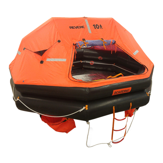
- Page 27 Description and Data 1. Product Specifications The SMLR-A(I) throw-overboard inflatable liferaft series. There are eight sizes with capacities of 4, 6, 8, 10, 12, 16, 20 and 25 persons. Throw-overboard rafts are available in a variety of packing options including Low- Profile containers (4, 6, 8), Round containers (6, 8, 10, 12, 16, 20, 25), Coastal Pack containers and valises (4, 6, 8), and High Drop containers (6, 8, 10, 12, 16, 20, 25).
- Page 28 The SMLR-D Davit Launch inflatable liferaft series. There are four sizes with capacities of 12, 16, 20 and 25 persons. Davit Launch rafts are available in a variety of packing options including Round con- tainers (12, 16, 20, 25) and High Drop containers (12, 16, 20, 25). Figure 2 - SMRL-D Davit Launch 9112 DESCRIPTION AND DATA...
- Page 29 2. Product Structure The design consists of two main buoyancy chambers made of natural rubber, an insulated floor and an automatic erecting canopy for all-weather protection that incorporates doorways, vents and a rainwater catchment system. The canopy is supported by an arch which is inflated via the upper buoyancy tube. There is a boarding ramp which is inflated via the lower buoyancy tube.
- Page 30 3. Inflation System Inflation Process SMLR-A(I) rafts use a one cylinder inflation system, while the SMLR-D rafts use two cylinders. Both inflation systems are activated by one painterline to inflate the upper and lower buoyancy tubes through two non-return inlet valves fitted on the upper tube and lower tube respectively.
- Page 31 5. Containers and Valises Containers are made of Glass re-enforced plastic (GRP). (See Figure 3 & Tables 2&3). Figure 3 - Container Dimensions 9112 DESCRIPTION AND DATA Page 107 MANUAL No. Jan 23/18...
- Page 32 Figure 3 - Container Dimensions Continued Figure 4 - Valise Dimensions 9112 DESCRIPTION AND DATA Page 108 MANUAL No. Jan 23/18...
- Page 33 6. Tables Raft Cylinder Charge CO Charge N Charge CO Charge N Cylinder Cylinder Size Qty. Throw-over (lbs.) Davit Launch (lbs.) Size TO Size DL 3.79 0.26 5.58 0.40 6.69 0.53 8.70 0.66 10.04 0.71 5.73 13.39 1.22 18.52 1.45 12.34 21.65 1.67...
- Page 34 Raft Weight lbs. (kg) Dim. A Pack in. (mm) Size A Pack B Pack Length Dia. 330 (150) 275 (125) 47 (1200) 27 (690) 385 (175) 308 (140) 57 (1450) 27 (690) 507 (230) 419 (190) 61.5 (1560) 30 (760) 595 (270) 463 (210) 65.5 (1660)
- Page 35 Servicing Intervals Test End of second year WP and B End of third year End of fourth year WP and B End of fifth year GI and WP End of sixth year WP and B End of seventh year End of eighth year WP and B End of ninth year End of tenth year...
- Page 36 SMLR-A SMLR-D Item Type (Throw-over) Type (Davit Launch) PSI/mmWG PSI/mmWG Working Pressure 1.9/53.5 2.9/80.3 Pressure Relief Valve (Safety) - AQF-I 2.9/80.3 AQF-II 4.2/116.25 Opening Pressure Relief Valve (Safety)- Re- AQF-I 1.9-2.1/53.5-58 AQF-II 2.9-3.1/80.3-85.8 seat Non-Return Press. Ltd. Valve DX-II 1.4/38.75 DX-II 1.4/38.75 Opening...
- Page 37 Type Raft Capacity USCG Approval Number 160.051/336/0 160.151/207/0 160.151/208/0 160.151/209/0 SMRL-A 160.151/210/0 160.151/211/0 160.151/212/0 160.151/213/0 160.151/214/0 160.151/215/0 SMRL-D (High Drop) 160.151/216/0 160.151/217/0 Table 9 - USCG Approval Numbers 9112 DESCRIPTION AND DATA Page 113 MANUAL No. Jan 23/18...
- Page 38 THIS PAGE INTENTIONALLY LEFT BLANK 9112 DESCRIPTION AND DATA Page 114 MANUAL No. Jan 23/18...
-
Page 39: Unpacking
CHAPTER 2 - UNPACKING Section Page Safety Procedures................Date of Manufacture/GI Test.............. Unpacking Procedure................. 9112 UNPACKING Page 201 MANUAL No. Jan 23/18... - Page 40 THIS PAGE INTENTIONALLY LEFT BLANK 9112 UNPACKING Page 202 MANUAL No. Feb 2/16...
- Page 41 Unpacking WEAR EYE, FACE, AND HAND PROTECTION 1. Safety Procedures Make sure the work area is clean and the lighting is sufficient. Use the following procedure if cutting container straps. WARNING: PUT ON FACE PROTECTION EQUIPMENT SUCH AS GOGGLES OR A FACE SHIELD AND GLOVES WHEN CUTTING THE STRAPS/ CORDS AROUND THE CONTAINER.
- Page 42 3. Unpacking the Liferaft Put the container onto a suitable pushcart or cradle. Make sure it is held securely. Position the push cart so that the container is next to the packing table. For throw-over containers, cut off the weak-links between the metal buttons of the upper half and lower half of the container and the packing straps of the container.
- Page 43 CHAPTER 3 - CLEANING Section Page General....................Procedure................... Liferaft....................Rigid Container................... Tables Cleaning Solvents and Materials (Table 1)......9112 CLEANING Page 301 MANUAL No. Feb 2/16...
- Page 44 THIS PAGE INTENTIONALLY LEFT BLANK 9112 CLEANING Page 302 MANUAL No. Feb 2/16...
-
Page 45: Cleaning
Cleaning 1. General CAUTION: Do not use any solvents other than those given in Table 1. Damage can be caused to the fabric. Item Description Application Toluene The solvent shall be applied by To clean fabrics for repair a lint free fabric pad, wet but not dripping with solvent Hard Soap To wash the liferaft... -
Page 46: Liferaft
3. Liferaft CAUTION: Do not let puddles of cleaning solution stay on the liferaft. Too much solvent can cause damage. Wash the liferaft with a solution of hard soap and water. Dry the liferaft with a clean, lint-free cloth. Use toluene to remove any oil or similar substance. Wash and dry the area as given in Steps A and B above. - Page 47 CHAPTER 4 - INSPECTION AND CHECKING Section Page Inspection of Raft................Inspection of Inflation System............Gas Cylinder..................Inspection of Non-return Inlet Check Valve........Inspection of Non-return Valve............Inspection of Non-return and Pressure-Limited Valve......Pressure Release (Safety) Valve............Inpection of Inflate/Deflate (Topping-Up) Valve......... Inspection of Lights................
- Page 48 THIS PAGE INTENTIONALLY LEFT BLANK 9112 INSPECTION AND CHECKING Page 402 MANUAL No. Feb 2/16...
-
Page 49: Inspection And Checking
Inspection and Checking 1. Inspection of Raft Inflate the liferaft with clean and dry compressed air by using special inflating hose until it is well formed. Take out the emergency pack and disconnect the canopy lights. Take a visual inspection of the liferaft. Wash and wipe with soft cloth if a liferaft is dirty, contaminated, or shows signs of mildew. - Page 50 Inspection of operating head WARNING: A GAS CYLINDER CAN BE A LETHAL PROJECTILE IF IT DIS- CHARGES TO ATMOSPHERE. ALWAYS ATTACH A RECOIL CAP TO THE GAS OUTLET WHEN HANDLING A FULLY CHARGED CYL- INDER. HOLD THE CYLINDER IN A VICE OR SAFETY CLAMPING DEVICE WHEN ATTACHING OR REMOVING AN FIRING HEAD.
-
Page 51: Gas Cylinder
Warning: Once the firing head has been removed, hold open end of valve away from hands to avoid injury from the activating knife. While keeping hands clear, pull out the firing wire to release the spring and activating knife. If the activating knife cannot be released, replace the firing head. -
Page 52: Inspection Of Non-Return Inlet Check Valve
See Chapter 1, Table 7 for the working pressure of the cylinder. Its valid period is 3 years. Any overdue cylinder shall be subjected to a hydraulic test of 1.5 times its working pressure. After test, the qualified cylinder shall be steel stamped with the date of the hydraulic test. -
Page 53: Inspection Of Non-Return Valve
Part No. Description Torque Bolt Fiber Gasket High Pressure Hose Fiber Gasket Upper Valve Section 25-30 Nm Seal Gasket Valve Core Spring Seal Ring Lower Valve Section Figure 3 - DJ -II Non-return Inlet Check Valve (Throw Over) 5. Inspection of non-return valve Check the one-way function of the valve. -
Page 54: Inspection Of Non-Return And Pressure-Limited Valve
6. Inspection of non-return & pressure-limited valve Check its opening and reseating pressure. Through the hole on PQ-II deflation valve, its pressure value can be adjusted by using a screw driver. Pressure value will be adjusted to a higher value if the screwdriver turns the adjusting nut clockwise or to a lower value counter-clockwise. - Page 55 7. Pressure Relief (Safety) Valve - PRV Inspect the working pressure range of the safety valve as per Chapter 1, Table 7 in this manual. If the working pressure is too low, adjust the valve core clockwise and if it is too high adjust it counter clockwise. If the adjustment fails, the valve-core, the spring or even the whole set of the safely valve shall be replaced.
- Page 56 8. Inspection of Inflate/Deflate (Topping-Up) Valve and Deflation Valve Inspect the rubber seal-rings/gaskets and replace them if they can not meet requirement. Part No. Description Rubber Plug Seal Ring Bolt Plastic Ring Upper Valve Part Seal Ring Rubber Gasket Plastic Gasket Lower Valve Part Figure 6 - PB-II Inflation/Deflation (Topping-Up) Valve 9112...
-
Page 57: Inspection Of Lights
Part No. Description Valve Cap Rubber Gasket Valve Body Figure 7 - PQ-II Deflation Valve for Boarding Ramp 9. Inspection of Lights Check the expiration date and replace it if the expiration date is within 1 year. Before packing the liferaft, the plug shall be inserted into the cell so as to switch on power automatically after the liferaft is inflated and formed. -
Page 58: Equipment Check
10. Equipment Check Take out the equipment (e.g. safety knife, sea anchor & line, rescue quoit & line, and paddles, etc.) from the liferaft, check them one by one and replace them if there is any defect. Open the equipment pack (emergency pack), take out the equipment items inside, check them one by one and replace those in poor condition due to damage or those that expire within 6 months. -
Page 59: Inspection Of Container
Ration packs are to be discarded if there is evidence of damage, defect or loss of vacuum which may affect the contents. Check all non-perishable items for condition, corrosion and damage. Renew as necessary. Check the drogues. If damaged, replace. If not, re-pack (Please refer to Chapter 7). - Page 60 THIS PAGE INTENTIONALLY LEFT BLANK 9112 INSPECTION AND CHECKING Page 414 MANUAL No. Jan 23/18...
-
Page 61: Testing And Troubleshooting
CHAPTER 5 - TESTING AND TROUBLESHOOTING Section Page General....................Preparation..................Test Procedures................. General Inflation test (GI) Necessary addition pressure test (NAP) Working pressure test (WP) Pressure Relief Valve Test Test of seam strength of floor (FS) Inspection of the canopy arch Suspension (Brindle) Overload Test (Davit only) High-pressure Hose Test Troubleshooting.................. - Page 62 THIS PAGE INTENTIONALLY LEFT BLANK 9112 TESTING AND TROUBLESHOOTING Page 502 MANUAL No. Feb 2/16...
- Page 63 Non critical parts such as some minor pockets shall be repaired so as to make them fit for purpose. If doubt exists as to the repair required, contact Revere Survival Inc. 9112 TESTING AND TROUBLESHOOTING Page 503 MANUAL No.
- Page 64 INFLATION TEST RECORD LIFERAFT TYPE: SERIAL No.: PACK LIFERAFTS WITHIN 48 HOURS OF TEST, UNLESS STORED UNDER APPROVED CONDITIONS. RE-TEST if not operationally packed within 30 days of test. Time/Date of Manometer Thermometer Barometer Temp/Pres Corrected Test Reading Reading Reading Variation Pressure SURVEY RECORD...
- Page 65 Barometer and Temperature Compensation Chart BUOYANCY TUBES HIGH PRESSURE Barometer Raft Pressure correction Raft Pressure correction in. Mercury (in HG) in. water (in WG) pounds/square inch (psi) +.01 +.136” .0049 +.02 +.27” .0098 +.03 +.40” .0147 +.04 +.54” .0196 +.05 +.68”...
- Page 66 2. Preparation Keep the records of all the inflation tests. A recommended format for the test cards is shown in Table 1. Keep the liferaft away from drafts and direct sunlight, as changes in temperature can affect pressure. Keep a solution of hard soap (not detergent), water, and a quantity of clean, dry, lint free cloths in the area.
- Page 67 T adaptor (P/N 57-GZ010) supplied by Revere. One end of the T adaptor is connected to the hose for compressed air and the other is connected with a hose of a pressure gauge.
- Page 68 Necessary additional pressure test (NAP) The NAP test shall be carried out in each annual service for a liferaft older than 10 years except that an early servicing is necessary by visual inspection. Plug the safety valve, connect the special T adaptor to the deflation & topping-up valve with the other end connected to a pressure gauge, then inflate compressed air into liferaft, raise the pressure gradually to 2 times of the working pressure and maintain the pressure for 5 min.
- Page 69 Carry out the Working Pressure test for at least 1h. During this test, the pressure drop shall be no more than 5% of the working pressure. Carry out the Pressure Relief Valve test listed in Section E. Working pressure test (WP) NOTE: WP test shall be carried out when a liferaft is not required to be sub- jected to NAP test or GI test.
- Page 70 SMLR-A SMLR-D Items Buoy Tube Buoy Tube Working 1.9/53.5 2.9/80.3 Pressure (PSI/in WG) Test time (h) Remained Pressure ≥ 1.8/50.8 ≥ 2.75/76.3 (PSI/in WG) Note: See Table 2 for adjustments in temperature and pressure Table 4 - Working Pressure Test for Liferafts If a liferaft cannot pass WP test, soap water shall be brushed on the connecting areas be- tween the liferaft body and the valve parts to check whether the assembly is in good con- dition.
- Page 71 Test of seam strength of floor (FS) A floor seam test is to be carried out on each liferaft at yearly intervals after the tenth year of the liferafts life, unless earlier servicing is deemed necessary as a result of visual inspection.
- Page 72 BUOYANCY TUBES RAFT FLOOR SUPPORT CHAIN CENTER RING SUPPORT CHAIN CENTER RING Figure 1 - Floor Seam Test Setup 9112 TESTING AND TROUBLESHOOTING Page 512 MANUAL No. Feb 2/16...
- Page 73 Suspension (Brindle) Overload test (Davit Launched Liferafts only - SMLR-D) This test shall be undertaken as required at the appointed age interval or after renewing any component or sub-assembly of the liferaft suspension arrangement, including the floor. It must be carried out before any pressure test(s).
- Page 74 4. Troubleshooting This table is given to help you to find a fault if there is a malfunction during the function test. The table shows the possible causes and the corrective action. If there is a failure or malfunction you should also look for signs of damage which could have caused the failure.
- Page 75 5. Inspection Certificate Upon successful completion of the inspected liferaft, Revere Survival Inc. Inspection Certifi- cate, P/N 57-70010 must be completed and distributed as follows: White copy: Vessel Pink copy: U.S. Coast Guard Inspector Green copy: Factory Gold copy: Service Facility Permanent File...
- Page 76 THIS PAGE INTENTIONALLY LEFT BLANK 9112 TESTING AND TROUBLESHOOTING Page 516 MANUAL No. Feb 2/16...
-
Page 77: Repair
CHAPTER 6 - REPAIR AND SERVICE Section Page General....................Adhesive..................... Preparation of Surfaces..............Preparation of Adhesives..............Application of Adhesive..............Repair Damaged Areas..............Types of patches Applying patches Testing repairs Repair limits More extensive damage Component Repair................Pressure Relief Valves Inflate / Deflate valves Inflation valves Firing Head Miscellaneous... - Page 78 THIS PAGE INTENTIONALLY LEFT BLANK 9112 REPAIR AND SERVICE Page 602 MANUAL No. Feb 2/16...
- Page 79 Repair and Service 1. General Repairs to fabrics normally consist of patching the damage with fabric patches. The patching fabric must be the same type of material as the item under repair When marking fabrics, use wax (e.g. Chinagraph) crayon. If a ‘major’ repair is carried out record the repairs on the liferaft log card.
- Page 80 Only the adhesive specified in this manual (FA 1030 adhesive and accelerator) shall be used for repairs. Although other unspecified adhesives may apparently bond surfaces together, they may also have unexpected negative side effects which will eventually cause premature failure. Keep the adhesive and curing agent in completely sealed airtight containers.
- Page 81 The fabric used for air-holding chambers has a high resistance to abrasion. Roughen the cleaned place and the rubber fabric repair patch with emery cloth. The size of the repair patch should be larger than the dilapidated area by 1.25” (3cm) at least. Apply the cleaning solvent again and allow to dry for at least 15 minutes.
- Page 82 For a liferaft floor covered by thermal protective foam with aluminum film coating. The repair of fabric is same as above. If the foam with aluminum film coating is damaged, replace it with a new one supplied by Revere. NOTE: a DRY JOINT will result if: -The adhesive becomes too dry between coats or at seam make-up.
- Page 83 Types of Patches A damaged area with its length less than 2” (5cm) will be repaired with an outside patch and a damaged area with its length over 2” (5cm) shall be repaired with both inside and outside patches. But the repaired area shall be no more than 23 in (150cm .
- Page 84 Applying Patches To apply patches, the following procedure must be followed: Thoroughly prepare and clear the damaged area, as described in Section 3, Preparation of Surfaces. Trim any frayed edges as necessary Make a cross cut in the air chamber, if necessary to enable you to insert the inner patch.
- Page 85 Figure 1 - Application of two patches 1.25” (3cm) 1.25” MIN. (3cm) MIN. 1.25” (3cm) MIN. Figure 2 - Patching 9112 REPAIR AND SERVICE Page 609 MANUAL No. Feb 2/16...
- Page 86 Ensuring the patch is placed centrally under the damage carefully press the two glued surfaces together. Use a spatula or roller to ensure that all air is expelled between the liferaft material and the patch and that there are no creases.
- Page 87 More extensive damage Repairs not described in this manual are not permitted except by permission from the Design Authority, Revere Survival Inc. Separate application must be made for each occasion when repair is proposed. 9112 REPAIR AND SERVICE Page 611 MANUAL No.
- Page 88 7. Component Repair Please refer to Chapter 10, Spare Parts for part numbers and descriptions of components listed in this section. Pressure Relief Valve - Replace Inflate/Deflate Valve - Replace Inflation Valve - Replace Firing Head NOTE: If the firing head is difficult to remove from the cylinder, it must be taken apart and repaired.
- Page 89 Replace the firing head and spring. O-ring Figure 5 - Firing Head Cap Install a new o-ring on the firing head cap (See Figure 5). Screw firing head cap back onto the body. Torque to 60Nm. Reset firing head. Follow Steps 5-8 in Chapter 4, Section 2.B for information on resetting the firing head.
- Page 90 Repair limits The limits of minor repairs are: • Damage to the gelcoat only, which does not penetrate the fiber glass mat. • Damage to the painted surface. The limits of major repairs are: • Holes or penetrating damage (i.e. through the fiber glass mat) over an area of more than 12in (77cm ) on the outer surface of the container.
- Page 91 Revere Survival Inc. The service record shall be signed by the inspector and the serviceman, while the certificate shall be signed by the chief of the service station.
- Page 92 THIS PAGE INTENTIONALLY LEFT BLANK 9112 REPAIR AND SERVICE Page 616 MANUAL No. Feb 2/16...
- Page 93 CHAPTER 7 - ASSEMBLY AND PACKING Section Page General..................Preparation of the Liferaft.............. Preparing the Container..............Vacuuming..................Attaching the Light................. Folding the Liferaft................. Emergency Equipment Packs............Container Labeling................. 9112 ASSEMBLY AND PACKING Page 701 MANUAL No. Jan 23/18...
- Page 94 THIS PAGE INTENTIONALLY LEFT BLANK 9112 ASSEMBLY AND PACKING Page 702 MANUAL No. Feb 2/16...
-
Page 95: Assembly And Packing
Assembly and Packing 1. General The work area must be clean, dry and free from sharp projections, with a smooth working surface, preferably of vinyl material. Special Tools, Equipment and Materials: Refer to Chapter 9 for the list of relevant items that are required during the assembly and repacking of a liferaft. - Page 96 Put the safety valve’s plug and the water-collecting bag back to their original place. Put the operation manual, immediate action card, anti-seasickness medicine and the log book which has been recorded into a plastic bag, seal it and then hang it onto the lifeline inside the liferaft .The service mark shall be stuck in an obvious place on the container.
- Page 97 Installation of cylinder Deflate the air from the liferaft. Fill in the service record the total weight of DOT cylinder, the weight of CO and N , the date. For high-drop packs, place an additional strip of foam around the operating head.
-
Page 98: Preparing The Container
3. Preparing the Container Cut a length of gasket strip neccessary to cover the rim of the container. Brush industrial cement into the seal groove of the upper half of container and onto the gasket strips. When cement becomes tacky, embed the strips into the groove. For container packing, cut a strip of heavy duty clear plastic sheeting so that it will completely cover the folded liferaft. - Page 99 5. Attachment of Light Figure 6 - Light Attachment Once the liferaft has been fully deflated, insert the light pin into the battery pack. Attach one end of a 24” cord (1.2mm, white, polyester) to the end of the pin and the other end to a loop in the floor of the raft.
-
Page 100: Folding The Liferaft
For High Drop rafts, place extra foam padding around the safety release valves and exterior light. Secure foam with 4” black gaffers tape. Foam should sit loose on the safety relief valve in order not to interfere with their function during activation. Figure 7 - Additional Foam Protection 6. - Page 101 Folding SMLR-A (4-8 Person, Low Profile Container) Place the liferaft neatly on a packing table in an open area, with enough room to maneuver the container during packing. The cylinder should be positioned adjacent to the edge of the packing table. Make sure any remaining air has been completely evacuated from the raft.
- Page 102 Lift the liferaft and place the cylinder end into the low profile container. Make sure the painterline cutout on the container is oriented in the same position as the firing head. Figure 9C - Folding, Step 4 Attach the end of painterline (nearest the inflation lanyard) to the towing rope closest to the cylinder head when folded.
- Page 103 Pass the painterline inflation lanyard through the loop in the firing wire and secure with a bowline knot. Pay attention not to twist painter with the activating line. Firing Wire Firing Wire Inflation Lanyard Figure 11 - Cylinder Orientation Figure 12 - Painterline to Firing Wire Pull 2-3 ft.
- Page 104 Figure 14 - Painterline Figure 15 - ID Tube Starting with the far end of the raft outside the container, make two folds until the raft is completely within the container. Figure 16 - Complete Raft Folding Fold the remaining plastic sheet over the raft. Do not tape down. 9112 ASSEMBLY AND PACKING Page 712...
- Page 105 Figure 17 - Plastic Cover After the raft and plastic cover are enclosed in the bottom container shell, place the top container shell over the bottom shell being sure to align the cutout hole with the grooves in the foam plug. Put two ratchet straps around the container, making sure the straps do not cover the grooves in the container.
- Page 106 Secure the container closed with two (2) container straps. Run the straps along the grooves in the container and tighten with a tensioning tool. Adjust the ends of each strap so that the outer most strap end is facing upwards and is approximately 1in.
- Page 107 If not attaching container to cradle, secure approximately 1ft. of the protruding painterline to container top with a small piece of vinyl tape. If attaching container to cradle: • Place container onto cradle and position it firmly in the center. •...
- Page 108 Folding SMLR-A (6-25 Person, Round Container) Place the liferaft neatly on a packing table in an open area, with enough room to maneuver the container during packing. The cylinder should be positioned adjacent to the edge of the packing table. Make sure any remaining air has been completely evacuated from the raft.
- Page 109 Figure 21B - Folding, Step 2 For rafts up to 10 person, fold the remainging side of the liferaft, keeping the seam of the fold aligned with the cylinder. For rafts over 10 person, after making the this fold, fold the edge of the raft back towards the seam. (Butterfly fold, see davit pack for pictures) Keep the ID tube free of the folds.
- Page 110 Attach the end of painterline (nearest the inflation lanyard) to the towing rope closest to the cylinder head when folded. Secure with a bowline knot and tape off the ends. Figure 22 - Painterline Attachment to Towing Line Pass the painterline inflation lanyard through the loop in the firing wire and secure with a bowline knot.
- Page 111 Figure 25 - Roll Raft Pull 2-3 ft. of the remaining free end of the painterline through the painterline plug in the container. Figure 26 - Painterline Hole Fold the plastic sheet over the raft and place the painterline sachet between the raft and the edge of the container.
- Page 112 Figure 27 - Painterline Cut a small hole in the plastic and pass the ID Tube through the hole. Secure to the side of the container with 4” black gaffers tape and leave the ID hanging outside of the container. After the raft and plastic cover are enclosed in the bottom container shell, place the top container shell over the bottom shell being sure to align top and bottom together.
- Page 113 Tie up the connection buttons on the upper and lower half of the container with weak-links by a method of series-wound and lead seal one weak-link at each side.The special weak link strips provided by Revere; one type for davit lauch liferafts (higher than 18 m), another type for regular liferaft (equal or lower than 18 m).
- Page 114 Figure 30 - Round Container and Cradle Place ID Tube underneath sealed weak-links. Place the inspection sticker on top of the container. If not attaching container to cradle, secure approximately 1ft. of the protruding painterline to container top with a small piece of vinyl tape. If attaching container to cradle: •...
- Page 115 Figure 31 - HRU Connection Figure 32 - Lashing Cord Figure 33 - Painterline Connection Make sure all labels are placed on the container and filled out completely. 9112 ASSEMBLY AND PACKING Page 723 MANUAL No. Jan 23/18...
- Page 116 Folding SMLR-A (4-6 Person, Coastal Pack Valise) Place the liferaft neatly on a packing table in an open area, with enough room to maneuver the container during packing. The cylinder should be positioned adjacent to the edge of the packing table. Make sure any remaining air has been completely evacuated from the raft.
- Page 117 Make the same 1/4 fold at the other end of the raft. Leave space in between the two folds for the final fold and storage of sea anchor. Figure 34C - Folding, Steps, 4 & 5 Place the packed sea anchor in the center of raft. Figure 34D - Sea Anchor Fold the raft over top of cylinder.
- Page 118 Place folded raft into valise with firing head oriented toward painterline patch on the valise. Leave ID tube hanging out of valise. Figure 35 - Put Into Valise Attach the end of painterline (nearest the inflation lanyard) to the towing rope closest to the cylinder head when folded.
- Page 119 Figure 37 - Painterline Attachment to Firing Wire Figure 38 - Painterline Attachment to Patch Making sure no line is hanging out, place painterline patch onto valise. Figure 39 - Painterline Attachment to Valise Close Valise making sure the ID tube remains outside the bag. Place an inspection sticker on the outside of the valise and fill out the raft information in the places provided with waterproof ink.
- Page 120 Folding SMLR-D (12-25 Person, Davit Launch) Place the liferaft neatly on a packing table in an open area, with enough room to maneuver the container during packing. The cylinder should be positioned adjacent to the edge of the packing table. Make sure any remaining air has been completely evacuated from the raft.
- Page 121 Fold the edge of the raft back towards the seam. Figure 40C - Folding Step 3 Place boarding ladder on top of raft. Fold the remainging side of the liferaft, keeping the seam of the fold aligned with the cylinder. Figure 40D - Folding Step 4 Fold the remaining edge of the raft back towards the seam.
- Page 122 Figure 40E - Folding Step 5 Lift raft end closest to the container, pull forward and fold over top of cylinder. Fold far enough so raft sits just inside edge of container. Lay out painterline assembly and prepare to attach painterline raft and inflation system.
- Page 123 Figure 42 - Painterline Attachment to Towing Line Pass each painterline inflation lanyard through the loops in the firing wires on the firing heads. Secure with a bowline knot and tape the ends. Pay attention not to twist painter with the activating line. Figure 43 - Painterline Inflation Lanyard Attachment to Cylinder Fold the front end of the plastic container lining over the folded end of the raft.
- Page 124 Figure 44 - ID Tube Lay the painterline sachet on top of the plastic and tape down with 4” black gaffers tape. Store any remaining painterline along the edge of the container bottom. Figure 45 - Painterline Placement Pull 2-3 ft. of the running end of the painterline through the painterline plug in the container.
- Page 125 Figure 45 - Fold into container Place the front bowsing line in front corner of the bottom container near the firing head. Keep the bowsing line loop outside of the container and secure the inside line to the container using 4” black gaffers tape. 9112 ASSEMBLY AND PACKING Page 733...
- Page 126 Figure 46 - Front Bowsing Line attachment Position davit ring toward the front and center of the container. Tie red webbing lop around davit ring for easy access. Figure 47 - Davit Ring Starting at the raft end farthest from the container, roll the remainder of the raft.
- Page 127 Fold the remaining container plastic over the folded raft. Figure 49 - Plastic Cover Place the back bowsing line in back corner of the bottom container near the firing head. Keep the bowsing line loop outside of the container and secure the inside line to the container using 4”...
- Page 128 Figure 51- Connection of Container Lines Put two ratchet straps around the container, making sure the straps do not cover the grooves in the container. Tighten the ratchet straps uniformly around the container. Make sure the upper half of the container mates with the lower half of the container correctly.
- Page 129 Figure 53 - Lashing Belt Secure lashing belt together by tying the weak link line with a triple knot. Figure 54 - Weak Link Knots Cover the weak link and any additional line with the hook-and-loop flap on the lashing belt. Figure 55 - Lashing Belt Cover 9112 ASSEMBLY AND PACKING...
- Page 130 Figure 56 - Davit Container and Cradle Place ID Tube underneath container lip and lashing strap. Place the inspection sticker on top of the container. If not attaching container to cradle, secure approximately 1ft. of the protruding painterline to container top with a small piece of vinyl tape. If attaching container to cradle: •...
- Page 131 Figure 57 - HRU Connection Figure 58 - Lashing Cord Figure 59 - Painterline Connection Make sure all labels are placed on the container and filled out completely. Bowsing line labels go on the front and back of the container. 9112 ASSEMBLY AND PACKING Page 739...
-
Page 132: Emergency Packs And Equipment
7. Emergency Equipment Packs 12 TO 16 TO 20 TO 25 TO Equipment Part No. 4 TO 6 TO 8 TO 10 TO & DL & DL & DL & DL Anti seasickness tablets 57-705-026 120 156 Bag, seasickness 57-705-005 Bailer, (Jug ) PVC 57-705-003 USCG Bellows... - Page 133 12 TO 16 TO 20 TO 25 TO Equipment Part No. 4 TO 6 TO 8 TO 10 TO & DL & DL & DL & DL Anti seasickness tablets 57-705-026 120 156 Bag, seasickness 57-705-005 Bailer, (Jug ) PVC 57-705-003 USCG Bellows 57-704-006...
- Page 134 Equipment Part No. 4 TO 6 TO 8 TO Bailer, (Jug ) PVC 57-705-003 USCG Bellows 57-704-006 Sea Anchor 57-704-003 Signal Mirror 57-705-019 Immediate action leaflet 57-70007 Spare Parts List 57-70024 Repair Plugs (Set of 2) 57-705-022 Lifesaving Signal Card 57-70013 Flashlight w/ Spare Bulb 57-705-018...
- Page 135 Number of Type of Liferaft Quantity (pc) Equipment Packs SMLR-A-4 (LP) SMLR-A-6 (LP) SMLR-A-6 (ROUND) SMLR-A-8 (LP) SMLR-A-8 (ROUND) SMLR-A-10 #2/#3 SMLR-A-12 #2/#3 SMLR-D-12 #2/#3 SMLR-A-16 #3/#4 SMLR-D-16 #3/#4 SMLR-A-20 SMLR-D-20 SMLR-A-25 #5/#6 SMLR-D-25 #5/#6 Note: The size [length x width x height (cm)] of equipment pack for each number: #1 80×35×20 #2 30×45×20 #3 45×45×20 #4 50×45×20 #5 55×45×20 #6 60×45×20...
- Page 136 Packed Equipment Bag Packed Water Bag When packing equipment/water bags for high-drop containers, wrap a layer of protective foam around the packed bag to prevent damage during the drop. Packed Equipment Bag for High-Drop 9112 ASSEMBLY AND PACKING Page 744 MANUAL No.
-
Page 137: Container Labeling
8. Container Labeling Check that all labels are fitted and positioned correctly and securely. Please refer to Chapter 10 for label identification. Do Not Cut Identification Logo This Side Up Data Panel Do Not Cut Radar Logo No Included Instructions Throw Over Inspection Sticker... - Page 138 Inspection Identification Sticker Do Not Roll This Side Up Data Panel Radar No Included Logo Logo Throw Over Instructions Bowsing Line Bowsing Line Davit Container Labels Valise Labels Record the liferaft details, onto the liferaft identification label and insert it into the identification tube.
-
Page 139: Storage
CHAPTER 8 - STORAGE Section Page General....................Storage Information................9112 STORAGE Page 801 MANUAL No. Feb 2/16... - Page 140 THIS PAGE INTENTIONALLY LEFT BLANK 9112 STORAGE Page 802 MANUAL No. Feb 2/16...
- Page 141 Storage 1. General This section describes the proper storage procedures for SMLR-A liferafts. Rafts should be stowed where they can easily be reached in an emergency. They should be stowed in a clean, dry, contaminant free area away from any heat source. Contaminants such as petroleum solvents, fuel, grease from oil, hydraulic fluids, and any acid or alkali material may have a detrimental effect on the fabrics and consequently on the life and performance of the raft.
- Page 142 When using a hose to wash the ship’s deck and liferaft installation, do not point the hose directly at the liferaft container. Fixed magnetic material in deciding on the stowage position of the liferafts, particularly in small vessels, consideration should be given to the possible effect on the ship’s compass of any ferrous metal in the liferaft or its stowage arrangements.
- Page 143 Stowage of liferafts in rigid containers. NOTE: Liferafts are usually packed in rigid containers with no other protection. Install the container the correct way up with the drainage apertures at the bottom. Keep the drainage apertures clear of obstructions such as the launching cradle sup- port structure.
- Page 144 NOTE: The hydrostatic release is a type that must be discarded (lifed item). It must be identified with the date of expiry and must be replaced by that date. They usually have an operational life which does not include a servicing period.
-
Page 145: Tools & Equipment
CHAPTER 9 - TOOLS AND EQUIPMENT Section Page General....................Tool List....................9112 TOOLS & EQUIPMENT Page 901 MANUAL No. Feb 2/16... - Page 146 THIS PAGE INTENTIONALLY LEFT BLANK 9112 TOOLS & EQUIPMENT Page 902 MANUAL No. Feb 2/16...
- Page 147 Tools and Equipment 1. General This section contains a listing of all tools, and equipment used to make the SMLR_A liferafts. To keep your tools in proper working order, take care of them by: • Inspecting and adjusting daily • Replacing worn or broken parts •...
- Page 148 THIS PAGE INTENTIONALLY LEFT BLANK 9112 TOOLS & EQUIPMENT Page 904 MANUAL No. Feb 2/16...
- Page 149 Item No. Image Description Part No. T-type gas-inlet valve 57-GZ001 (PF-V Operating Head) PB-II T-adaptor 57-GZ010 Manometer (6 psi) Precisior pressure gauge (14.5 psi) Reseat Tool for Type V 57-GZ016 operating head Tool for Type V operating 57-GZ017 head Tool for PB-II valve 57-GZ018 Tool for AQF-II safety valve 57-GZ019...
- Page 150 Item No. Image Description Part No. Paint Brush Roundhead Scissors Small Roller (Metal) 80-338-003 Lead Seal Tool 57-703-002 9112 TOOLS & EQUIPMENT Page 906 MANUAL No. Jan 23/18...
-
Page 151: Spare Parts
CHAPTER 10 - SPARE PARTS Section Page General....................1003 Spare Parts List.................. 1005 9112 SPARE PARTS Page 1001 MANUAL No. Feb 2/16... - Page 152 THIS PAGE INTENTIONALLY LEFT BLANK 9112 SPARE PARTS Page 1002 MANUAL No. Feb 2/16...
- Page 153 Spare Parts 1. General The spare parts list has been prepared for the sole purpose of identifying and/or ordering replacement parts. NOTE: Images are not to scale. 9112 SPARE PARTS Page 1003 MANUAL No. Feb 2/16...
- Page 154 THIS PAGE INTENTIONALLY LEFT BLANK 9112 SPARE PARTS Page 1004 MANUAL No. Feb 2/16...
- Page 155 2. Spare Parts List Operating Head PF-V. Application: SMLR-A, SMLR-D Item No. Image Description Part No. Firing Head (Throw-over) 57-FS005-1 Firing Head (Davit) 57-FS006-1 Activating Knife 57-FS006-2 Spring 57-FS006-3 Lower part of Operating Head 57-FS006-4 (Contains cylinder valve, flex tube) Firing Wire (Throw-over) 57-FS005-5 Firing Wire (Davit)
- Page 156 Non-return Inlet Valve DJ-II-45 / DJ Application: SMLR-A, SMLR-D Item No. Image Description Part No. Non-return Inlet Valve DJ-II-45 57-FJ005 (SMLR-D) Non-return Inlet Valve DJ 57-FJ008 (SMLR-A) Pressure Relief (Safety) Valve AQF-I / AQF-II Application: SMLR-A, SMLR-D Item No. Image Description Part No.
- Page 157 Deflation Valve PQ-II. Application: SMLR-A, SMLR-D Item No. Image Description Part No. Deflation Valve 57-FP003 Valve Cap 57-FP003-1 Rubber Gasket 57-FP003-2 Non-return Valve DF-I. Application: SMLR-A, SMLR-D Item No. Image Description Part No. Non-return Valve 57-FD002 (canopy arch) Non-return and Pressure Limited Valve DX-II. Application: SMLR-A, SMLR-D Item No.
- Page 158 Cylinders: USDOT DOT-3AA Application: SMLR-A, SMLR-D Item No. Image Volume Raft Part No. SMLR-A-4 57-702-001 SMLR-A-6 57-702-002 SMLR-A-8 57-702-003 SMLR-D-12 SMLR-A-10 57-702-004 SMLR-D-16 SMLR-A-12 57-702-005 SMLR-D-20 57-702-006 SMLR-A-16 57-702-007 SMLR-D-25 57-702-008 SMLR-A-20 57-702-009 SMLR-A-25 57-702-010 9112 SPARE PARTS Page 1008 MANUAL No.
- Page 159 Hose SG/T Application: SMLR-A, SMLR-D Item No. Image Description Part No. High Pressure Hose 4P 57-SG/T-V-570 High Pressure Hose 6/8P 57-SG/T-II-610 High Pressure Hose 10P 57-SG/T-II-650 High Pressure Hose 12/16P 57-SG/T-II-700 High Pressure Hose 20/25P 57-SG/T-II-750 Hose Cover 57-703-003 3 Hole Bolt for Inlet Valve 57-SJ002 Hydrostatic Release Unit Application: SMLR-A, SMLR-D...
- Page 160 Equipment Pack Components Application: SMLR-A, SMLR-D Item No. Image Description Part No. Paddle 57-704-004 First Aid Kit 57-705-014 Food Ration 45-2400FB Fresh Water 90-WATER4OZ Sea Sickness Bag 57-705-005 9112 SPARE PARTS Page 1010 MANUAL No. Jan 23/18...
- Page 161 Item No. Image Description Part No. Jackknife 57-705-017 Floating Knife 57-705-001 Rescue Quoit and Line 57-704-002 Pump 57-704-006 Waterproof Flashlight 57-705-018 Daylight Signaling Mirror 57-705-019 9112 SPARE PARTS Page 1011 MANUAL No. Jan 23/18...
- Page 162 Item No. Image Description Part No. Bailer 57-705-003 Sponge 57-705-020 Sea-anchor and Line 57-704-003 (HM-I) ParaRockets (USCG) 45-963100 Handflares (USCG) 45-9162800 Smokes (USCG) 45-9192000 Whistle 58-505-001 9112 SPARE PARTS Page 1012 MANUAL No. Jan 23/18...
- Page 163 Item No. Image Description Part No. Fishing Kit 57-705-023 Tin-opener 57-705-007 Graduated Drinking Cup 57-705-008 Thermal Protective Aids 57-705-024 Anti-Seasickness Tablets 57-705-026 Flashlight Bulb 57-705-029 “D” Cell Batteries 10-D-BATTERIES 9112 SPARE PARTS Page 1013 MANUAL No. Jan 23/18...
- Page 164 Item No. Image Description Part No. Lifesaving Signal Card 57-70013 ID Card 57-70014 Immediate Action Card 57-70007 Survival at Sea Manual 57-70015 Log Book (SMLR-A) 57-70009-1 9112 SPARE PARTS Page 1014 MANUAL No. Jan 23/18...
- Page 165 Item No. Image Description Part No. Log Book (SMLR-D) 57-70009-2 Operating Manual 57-70008 Spare Parts List (SMLR-A 4-25) 57-70011- (SMLR-D 12-25) (1-12) 4 PERSON SHOWN 9112 SPARE PARTS Page 1015 MANUAL No. Jan 23/18...
- Page 166 Repair Kit: 57-70006 (Parts not sold separately) Application: SMLR-A, SMLR-D Item No. Image Description Part No. Emergency Plug Emergency Clamp Emery Paper Rubber Fabric Rubber Mucilage Scissors 9112 SPARE PARTS Page 1016 MANUAL No. Jan 23/18...
- Page 167 Container Labels Application: SMLR-A, SMLR-D Item No. Image Description Part No. ID Label Revere (6-25 person) 57-70002-1 ID Label Revere (4 person) 57-70002-2 ID Label 3Si (6-25 person) 57-70002-3 ID Label 3Si (4 person) 57-70002-4 Do Not Cut Label 95-43028-1...
- Page 168 Item No. Image Description Part No. Inspection Data Label (4 person) 57-70003-1 Inspection Data Label 57-70003-2 (6-25 person) Revere Logo 62-20008-1 3Si Logo 62-20008-2 Do Not Roll Label 57-70016 This Side Up Label 62-20006-1 9112 SPARE PARTS Page 1018 MANUAL No.
- Page 169 Item No. Image Description Part No. Throw Overboard (LP) Label 57-70017-1 Throw Overboard (Round) Label 57-70017-2 16 person or less Davit Launch Label 57-70018 Cut Off Label 57-70019 Bowsling Label 57-70020 Radar Reflector Not Included 57-70012 9112 SPARE PARTS Page 1019 MANUAL No.
- Page 170 Containers Application: SMLR-A, SMLR-D See Chapter 1, Figure 3 for additional information on containters. Item No. Description Part No. Flat Container SMLR-A-4 57-701-009 Flat Container SMLR-A-6/8 57-701-010 Container SMLR-A-6 57-701-001 Container SMLR-A-8 57-701-002 Container SMLR-A-10 57-701-003 100S Container SMLR-A-12 57-701-004 101S Container SMLR-A-16 57-701-005...
- Page 171 Item No. Description Part No. 103S Container SMLR-D-12 57-701-011 104S Container SMLR-D-16 57-701-012 105S Container SMLR-D-20 57-701-007 106S Container SMLR-D-25 57-701-008 107S Container SMLR-A-6 High Drop 57-701-019 108S Container SMLR-A-8 High Drop 57-701-020 109S Container SMLR-A-10 High Drop 57-701-021 110S Container SMLR-A-12 High Drop 57-701-022 111S...
- Page 172 Valises Application: SMLR-A Coatal Pack Item No. Description Part No. 117S Revere Valise 4P 57-701-013 118S Revere Valise 6P 57-701-014 119S Revere Valise 8P 57-701-015 120S 3Si Valise 4P 57-701-016 121S 3Si Valise 6P 57-701-017 122S 3Si Valise 8P 57-701-018...
- Page 173 Misc. Material Application: SMLR-A, SMLR-D Item No. Image Description Part No. 123S Equipment Bag #1 57-705-002 124S Equipment Bag #2 57-705-009 125S Equipment Bag #3 57-705-010 126S Equipment Bag #4 57-705-011 127S Equipment Bag #5 57-705-012 128S Equipment Bag #6 57-705-013 129S Painterline - 28m...
- Page 174 Item No. Image Description Part No. 131S Cradle - Low Profile 4P 40-LP1-CRADLE 132S Cradle - Low Profile 6P 40-LP2.5-CRAD 40-CRADASSY 133S Cradle - Round 6/25P -6-25 134S Shackle - Long D 10-362S-08 Neoprene Stripping 135S 10-STRIP-1/8 (LP Containers) 136S Hold Down Strap LP 4P 45-41176-113 137S...
- Page 175 Item No. Image Description Part No. 142S Lashing Cord (Round Containers) 57-QT006 143S Wire Clip (Round Containers) 57-QT007 Container Strapping 144S 62-HYF-AB-1 (LP Containers) 145S Strapping Crimp (LP Containers) 58-501-006 146S Sleeve - Crimp Protection 95-43027-1 147S White 1” Vinyl Tape 10-TAPE-1 148S Gaffers 4”...
- Page 176 Item No. Image Description Part No. 154S Lead Seal 57-YB029 155S Embedded Strip 57-SS003 156S ID Canister 57-BS001 157S Polyamide Tape (white) 57-SD003 158S Polyamide Tape (yellow) 57-SD004 159S Polyamide Tape (orange) 57-SD005 160S Polyamide Rope (Towing) 57-SD011 161S Polyamide Rope (Sea Anchor) 57-SD012 162S Polyamide Rope...
- Page 177 167S Aluminum Film 57-J-3 168S Glue FA 1030 (Sold as a set) 95-306-008 169S Commercial Inspection Certificate 57-70010 Sticker USCG for Certificate 170S 62-20005-1 Revere Sticker USCG for Certificate 171S 62-20005-2 9112 SPARE PARTS Page 1027 MANUAL No. Jan 23/18...
- Page 178 THIS PAGE INTENTIONALLY LEFT BLANK 9112 SPARE PARTS Page 1028 MANUAL No. Feb 2/16...
Need help?
Do you have a question about the 3SI SMLR-A I and is the answer not in the manual?
Questions and answers