Table of Contents
Advertisement
Quick Links
5 3 2 3 H i g h w a y A v e n u e
J a c k s o n v i l l e , F L 3 2 2 5 4
T e l : ( 9 0 4 ) 5 0 3 - 9 7 3 3
F a x : ( 9 0 4 ) 5 0 3 - 9 7 1 9
w w w . r e v e r e s u r v i v a l . c o m
S e r v i c e Ma n u a l
C o a s t a l C r u i s e r 2 . 0
C o a s t a l C o m m a n d e r 2 . 0
O ff s h o r e C o m m a n d e r 2 . 0
Ma n u a l N u mb e r : 9 1 2 0
S e c o n d E d i t i o n
Advertisement
Chapters
Table of Contents

Related Manuals for Revere Coastal Cruiser 2.0


Summary of Contents for Revere Coastal Cruiser 2.0
- Page 1 5 3 2 3 H i g h w a y A v e n u e J a c k s o n v i l l e , F L 3 2 2 5 4 T e l : ( 9 0 4 ) 5 0 3 - 9 7 3 3 F a x : ( 9 0 4 ) 5 0 3 - 9 7 1 9 w w w .
- Page 3 DOCUMENTING A REVISION Record the Revision No. and Revision Date. Remove the old sheet and replace it with the revised copy. Record the Insert Date and then initial in the Inserted By column. Revisions made ONLY by Revere Survival Inc. INSERTED INSERTED REV.
- Page 4 THIS PAGE INTENTIONALLY LEFT BLANK October 7/2016 9120 Record of Revisions RR - 2...
- Page 5 Revere Survival, Inc., Jacksonville, FL 32254 T. 904.503.9733 F. 904.503.9719 LETTER OF TRANSMITTAL 9120 Holders of Manual No. Coastal Cruiser/Commander 2.0 Title: Service Manual Revision No.: Date: May 24, 2018 Signed: Date: 5/24/2018 Director of Technical Publications Pages Affected Revision Highlights...
- Page 7 SERVICE BULLETIN All service bulletins which are incorporated into this manual are required to be recorded in this list. All updates to this list will be made by the owner of the manual. SERVICE DATE OF DATE TITLE/DESCRIPTION REV. No. BULLETIN No.
- Page 8 THIS PAGE INTENTIONALLY LEFT BLANK October 7, 2016 9120 Service Bulletin SB - 2...
- Page 9 LIST OF EFFECTIVE PAGES PAGE PAGE PAGE TITLE ISSUE DATE PAGE TITLE ISSUE DATE Title Page May 24/18 Oct 7/16 Oct 7/16 Revision Record RR-1 May 24/18 2-10 Oct 7/16 RR-2 Oct 7/16 2-11 Oct 7/16 2-12 Oct 7/16 Service Bulletin SB-1 Oct 7/16 2-13...
- Page 10 PAGE PAGE PAGE TITLE ISSUE DATE PAGE TITLE ISSUE DATE 4-14 May 24/18 7-13 Oct 7/16 4-15 May 24/18 7-14 Oct 7/16 4-16 May 24/18 Assembly 4-17 May 24/18 Section 8 Oct 7/16 4-18 Oct 7/16 Oct 7/16 Cleaning Oct 7/16 Section 5 Oct 7/16 Oct 7/16...
- Page 11 PAGE PAGE ISSUE DATE PAGE TITLE ISSUE DATE Storage 11-18 May 24/18 Section 9 Oct 7/16 11-19 May 24/18 Oct 7/16 11-20 May 24/18 Oct 7/16 11-21 May 24/18 Oct 7/16 11-22 May 24/18 Tools Appendix A Section 10 10-1 Oct 7/16 Cert.
- Page 12 PAGE PAGE ISSUE DATE PAGE TITLE ISSUE DATE October 7, 2016 9120 EP - 4...
- Page 13 LIST OF ASSOCIATED PUBLICATIONS None Listed October 7, 2016 9120 Associated Publications AP - 1...
- Page 14 THIS PAGE INTENTIONALLY LEFT BLANK October 7, 2016 9120 Associated Publications AP - 2...
- Page 15 LIST OF ABBREVIATIONS/SYMBOLS DEFINITION ABBREVIATION Degrees ° Percent Calories cal. Centigrade/Celcius Cubic Centimeter(s) Centimeter Centimeters of Mercury cm Hg Cubic Inch Farenheit Figure Fig. Fluid Ounce fl oz. Foot or Feet Gram Gram per Square Centimeter g/cm Inch (s) Inches of Mercury inHg Inside Diameter I.D.
- Page 16 THIS PAGE INTENTIONALLY LEFT BLANK October 7, 2016 9120 List of Abbreviations AB - 2...
-
Page 17: Table Of Contents
TABLE OF CONTENTS DESCRIPTION SECTION – PAGE No. Introduction Description, Data, and Operation Disassembly Testing and Fault Isolation Cleaning Service Inspection and Check Repair Assembly and Packing Storage Tools, Equipment, and Materials 10-1 Spare Parts 11-1 Appendix A October 7, 2016 9120 Table of Contents TC - 1... - Page 18 THIS PAGE IN INTENTIONALLY LEFT BLANK October 7, 2016 9120 Table of Contents TC - 2...
-
Page 19: Introduction
CHAPTER 1 INTRODUCTION General Manual Breakdown Shop Verification Warnings, Cautions, and Notes Layout of Manual List of Effective Pages Record of Revision Associated Publications October 7, 2016 9120 Introduction 1 - 1... - Page 20 THIS PAGE INTENTIONALLY LEFT BLANK October 7, 2016 9120 Introduction 1 - 2...
- Page 21 Revere Survival Inc. MANUAL BREAKDOWN Shop Verification The sections within this manual have been verified at the Revere Survival Inc. facility by actually performing all functions such as disassembly, assembly, and testing. Warnings, Cautions, and Notes Revere Survival Inc.
- Page 22 List of Effective Pages The list of effective pages details all the pages that are contained in the manual and indicates the issue dates of those pages allowing the manual content to be checked for completeness and accuracy. This list is included in the preliminary pages of this manual. Record of Revision When required, the pages of this manual will be amended, approved, and re-issued as a revision.
-
Page 23: Description, Data, And Operation
CHAPTER 2 DESCRIPTION, DATA, AND OPERATION General Description Overview Detail 1. Standard Equipment 2. Inflation System Data Operation October 7, 2016 9120 Description 2 - 1... - Page 24 THIS PAGE INTENTIONALLY LEFT BLANK October 7, 2016 9120 Description 2 - 2...
-
Page 25: General
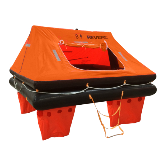
GENERAL This section contains descriptive and operational information covering the Coastal Cruiser 2.0, and the Coastal and Offshore Commander 2.0 liferafts (See Figs. 1&2). The Cruiser and Commander 2.0 liferafts’ self-inflation system is initiated manually. They are stored in either a container or a valise for rapid, easy access by passengers and crew in the event of an emergency. - Page 26 FIGURE 1 – COASTAL CRUISER 2.0 AND COASTAL COMMANDER 2.0 Canopy Interior Lifeline Buoyancy Tube Zippered Door Exterior Lifeline Boarding Ladder Ballast Bags October 7, 2016 9120 Description 2 - 4...
- Page 27 FIGURE 2 – OFFSHORE COMMANDER 2.0 Locator Light Canopy Reflective Tape Interior Lifeline Exterior Lifeline Buoyancy Tube Zippered Door Boarding Ladder Ballast Bags October 7, 2016 9120 Description 2 - 5...
- Page 28 THIS PAGE INTENTIONALLY LEFT BLANK October 7, 2016 9120 Description 2 - 6...
-
Page 29: Overview
DESCRIPTION OVERVIEW Coastal Cruiser 2.0 and Coastal Commander 2.0 Liferafts are designed for coastal use and are available in a 6 person capacity. Offshore Commander 2.0 liferafts are designed for offshore use and are available in 4, 6, and 8 person capacities. - Page 30 Liferafts should be handled carefully in transportation without rolling. They should be stored in a dry and ventilated place in a warehouse or other secure location. There shall be no more than 2 layers of overlapping stacking during storage. Additionally, they should be stored in such a way that the “This Side Up”...
-
Page 31: Detail
DETAIL Standard Equipment The Cruiser and Commander Liferafts are equipped with the following items and features (Figs. 1&2): Mooring Line This line is used for positioning the inflated raft for boarding. Painterline Pulling on this 36ft. (11m) line will activate the inflation system and begin raft deployment. It can also be used as a mooring line after activation. - Page 32 Boarding Ladder The external Ladder is positioned in front of the canopy door to allow for easy entrance into the raft. An interior ladder is provided in conjunction with the ramp and exterior ladder to assist with boarding. 10. Survival Equipment Pack These packs contain emergency rations and items to aid raft occupants for survival at sea.
-
Page 33: Inflation System
Inflation System All raft models have three air-holding compartments: upper and lower buoyancy tubes, and a canopy arch-tube. The upper buoyancy tube is pneumatically connected to the inflatable arch- tube while remaining separate from the All rafts are constructed with pressure release valves to prevent over inflation and tube bursting. They are also equipped with manual topping-off valves which can be used to provide additional inflation with the hand pump provided, or as inflation points for testing and service. - Page 34 FIGURE 3 – COASTAL CRUISER 2.0 VALISE AND CONTAINER FIGURE 4 – COASTAL COMMANDER 2.0 VALISE AND CONTAINER FIGURE 5 - OFFSHORE COMMANDER 2.0 VALISE AND CONTAINER October 7, 2016 9120 Description 2 - 12...
-
Page 35: Data
DATA Tube Operating Pressure (Working) Capacity Minimum: 1.54psi 6 Persons Coastal Cruiser/Commander 2.0 4, 6, 8 Persons Offshore Commander 2.0 Tube Burst Pressure +6psi Color Buoyancy tubes: Black Inflation System Canopy: Orange Arch-tube: Black Coastal Cruiser/Coastal Commander 2.0/ Ballast bags: Orange Offshore Commander 2.0 4/6 person 58-502-009... - Page 36 L in. x W in. x H in. L in. x W in. x H in. (canopy H) (Kg.) (cm) (cm) Coastal Cruiser 2.0 6 28 x 17 x 10 78 x 78 x 50 62 (28.0) 45-CCZR-6V (71.10 x 25.40 x 43.20) (199 x 199 x 127) Coastal Commander 2.0 6...
- Page 37 WT. LBS WT. LBS RAFT MODEL (kg) (kg) Coastal Cruiser 2.0 6 3.97 to 4.03 (1.80 to 1.83) .10 to .12 (.045 to .054) Coastal Commander 2.0 6 3.97 to 4.03 (1.80 to 1.83) .10 to .12 (.045 to .054) Offshore Commander 2.0 4...
- Page 38 THIS PAGE INTENTIONALLY LEFT BLANK October 7, 2016 9120 Description 2 - 16...
-
Page 39: Operation
OPERATION It is CRITICAL that the container is not thrown overboard without FIRST having been secured to a strong point on the ship. If this instruction is not observed, the container may be lost, and/or personnel may be pulled overboard with the container. Caution: DO NOT attempt to unpack and inflate the liferaft on deck;... - Page 40 FIGURE 6 - DEPLOYMENT October 7, 2016 9120 Description 2 - 18...
-
Page 41: Disassembly
CHAPTER 3 DISASSEMBLY General Procedures October 7, 2016 9120 Disassembly 3 - 1... - Page 42 THIS PAGE INTENTIONALLY LEFT BLANK October 7, 2016 9120 Disassembly 3 - 2...
- Page 43 GENERAL It will be necessary at normal service and overhaul periods (See Chapter 2 – Description, Data, and Operation) to remove the packed liferaft from the vessel. Ensure the working area is clean and dry, free from sharp projections, and large enough to fit the liferaft. The work surface should be smooth, preferably constructed of linoleum or PVC covering.
- Page 44 THIS PAGE INTENTIONALLY LEFT BLANK October 7, 2016 9120 Disassembly 3 - 4...
- Page 45 PROCEDURES Remove the packed liferaft in its valise/container from the vessel. Caution: Do not pull or jerk the painterline as this may cause operation of the inflation system. Inadvertent activation of the inflation system may cause personal injury or damage to raft components. Remove the liferaft from the valise/container as follows: Container Disconnect the taped painterline from the outside of the container.
- Page 46 FIGURE 1 – CUTTING CONTAINER STRAPS Valise Carefully pull open the Velcro fasteners on the valise. Remove the looped painterline from around the painterline patch on the valise. For Cruiser rafts, carefully untie the painterline and pass the end of the painterline back through the inflation valve pull cable loop.
- Page 47 For Commander rafts, untie the mooring line from inside the vacuum bag Untie survival equipment pack, and place it aside for further inspection. (See Chapter 6, Inspection and Chapter 8, Assembly for further instructions on the equipment packs) Unfold it and lay it out flat with canopy on the top. Using a wrench, disconnect the cylinder inflation valve from both valve inlet checks.
- Page 48 THIS PAGE INTENTIONALLY LEFT BLANK October 7, 2016 9120 3 - 8...
-
Page 49: Testing And Fault Isolation
CHAPTER 4 TESTING AND FAULT ISOLATION General Preparation Leakage Test Procedures General Inflatable Chambers (Air Holding or Working Pressure Test) Function Tests General Light Topping-Off Valves Pressure Relief Valves (Overpressure Test) Inlet Check Valves Gas Cylinder and Inflation Valve Cylinder Valve Inflation Test Fault Isolation/Troubleshooting May 24, 2018 9120... - Page 50 THIS PAGE INTENTIONALLY LEFT BLANK October 7, 2016 9120 Testing 4 - 2...
-
Page 51: General
GENERAL This section contains instructions for minimum performance testing of the Coastal Cruiser 2.0, Coastal Commander 2.0 and Offshore Commander 2.0 Liferafts. The performance test provides a functional equipment check to establish the ability of the systems and components to perform required design function or before the reinstallation of rafts removed from service. - Page 52 THIS PAGE INTENTIONALLY LEFT BLANK October 7, 2016 9120 Testing 4 - 4...
- Page 53 Keep records of ALL inflation tests. Make blank copies of this form and fill out charts when needed. LEAKAGE TEST RECORD CHART LIFERAFT TYPE No. SERIAL No. INSPECTED BY: CHECKED BY: PACK LIFERAFTS WITHIN 48 HOURS OF TEST, UNLESS STORED UNDER APPROVED CONDITIONS RE-TEST if not operationally packed within 30 days of test Date __________ Date __________...
- Page 54 THIS PAGE INTENTIONALLY LEFT BLANK May 24, 2018 9120 Testing 4 - 6...
-
Page 55: Preparation
PREPARATION Keep record of ALL inflation tests. Copies of Test Record Charts are provided in the previous section. Make blank copies and store at the end of the Section. Protect liferafts from drafts and direct sunlight as temperature affects pressure. Keep at hand a solution of mild liquid soap (NOT detergent) and water, and a plentiful supply of clean, dry, lint-free cloth. - Page 56 THIS PAGE INTENTIONALLY LEFT BLANK October 7, 2016 9120 Testing 4 - 8...
-
Page 57: Leakage Test Procedures
LEAKAGE TEST PROCEDURES GENERAL Each inflatable part of the main structure must be tested separately. All test results should be recorded on the Leakage Test Record Chart (See Table A). The structure consists of all the chambers served by the gas inflation system. These include: ... -
Page 58: Inflatable Chambers (Air Holding Or Working Pressure Test)
INFLATABLE CHAMBERS (AIR HOLDING OR WORKING PRESSURE TEST) Each chamber must be tested separately, but simultaneously over a period of approximately 1 hour. Using an inflation tool (Part No. 95- 41128-101) and clean, dry shop air, inflate the upper buoyancy chamber to until the pressure relief valve (PRV) opens. This will also inflate the arch- tube. - Page 59 Refer to Table C for correction quantities due to changes in barometric pressure or temperature over the test period. BUOYANCY TUBES - HIGH PRESSURE Change in Barometric Pressure, P (inHg) Raft Tube Pressure Correction (psi) -.30 -.1470 -.25 -.1225 -.20 -.0980 -.15 -.0735...
- Page 60 BUOYANCY TUBES - HIGH PRESSURE Change in Temperature (°F) Raft Tube Pressure Correction (psi) -10° +.31 -9° +.28 -8° +.25 -7° +.22 -6° +.19 -5° +.16 -4° +.12 -3° +.09 -2° +.06 -1° +.03 0° +1° -.03 +2° -.06 +3° -.09 +4°...
- Page 61 FIGURE 1 – DIGITAL MANOMETER May 24, 2018 9120 Testing 4 - 13...
-
Page 62: General
FUNCTION TEST PROCEDURES GENERAL A full function test is not required for normal service. The following items listed will need to be assessed for proper operation and restored if they are non-functional. Refer to Chapter 7 – Repair for repair/replacement instructions for failed components. LIGHT Check the unit expiration date. -
Page 63: Inlet Check Valves
The valve will “pass inspection” if it opens at 2.31 psig MAX and closes and 1.64 psig MIN. 10. If the valve fails to operate within the limits given above, it must be replaced. INLET CHECK VALVES Using clean, dry shop air, inflate the compartment to 1.54psi. Spray a solution of soapy water on top of the valve. -
Page 64: Cylinder Valve Inflation Test
CYLINDER VALVE INFLATION TEST Note: Do not perform the Cylinder Valve Inflation Test with the cylinder still attached to the raft. Remove cylinder from raft (See Chapter 3 – Disassembly). Install diffuser caps onto the inflation valve. Check the weight of the cylinder to make sure no leaks have occurred. Place cylinder into a vise and tighten down. - Page 65 FAULT ISOLATION The table below is given to facilitate the locations of troubles in the event of malfunction during the function test, their probable causes, and corrective action. In addition to using this table, visually check the liferaft and equipment for evidence of damage or signs of failure. Fault Probable Cause Corrective Action...
- Page 66 THIS PAGE INTENTIONALLY LEFT BLANK October 7, 2016 9120 Testing 4 - 18...
-
Page 67: Cleaning
CHAPTER 5 CLEANING General Procedures Liferafts Rigid Container Valise October 7, 2016 9120 Cleaning 5 - 1... - Page 68 THIS PAGE INTENTIONALLY LEFT BLANK October 7, 2016 9120 Cleaning 5 - 2...
- Page 69 GENERAL This section contains instructions on cleaning the Cruiser and Commander liferafts. When necessary, periodic inspection and cleaning deemed should be performed. The working area must be free from chemicals, corrosives, and solvents. Note: Only clean rafts if exceptionally dirty or absolutely necessary. CLEANING MATERIALS Caution: Use only cleaning agents used in Table A.
- Page 70 THIS PAGE INTENTIONALLY LEFT BLANK October 7, 2016 9120 Cleaning 5 - 4...
- Page 71 PROCEDURES Warning: All solvents: Flammable; Keep away from uncovered lights. Use solvents only in a well ventilated atmosphere. Do not splash into eyes and avoid breathing in the vapors. Use a barrier cream on hands and wash them after using solvents. Liferafts Wash the liferaft with a solution of mild liquid soap (Item 1) and water.
- Page 72 THIS PAGE INTENTIONALLY LEFT BLANK October 7, 2016 9120 Cleaning 5 - 6...
-
Page 73: Service Inspection And Check
CHAPTER 6 SERVICE INSPECTION AND CHECK General Gas Inflation System Emergency Pack Valise/Container Pack October 7, 2016 9120 Inspection 6 - 1... - Page 74 October 7, 2016 9120 Inspection 6 - 2...
- Page 75 GENERAL THIS PAGE INTENTIONALLY LEFT BLANK October 7, 2016 9120 Inspection 6 - 3...
- Page 76 Coastal Cruiser 2.0 liferafts are to first be inspected after 2 years and then annually thereafter.
- Page 77 GENERAL THIS PAGE INITIALLY LEFT BLANK October 7, 2016 9120 Inspection 6 - 5...
- Page 78 Warning: The charged gas cylinder can become a lethal projectile if discharged to atmosphere when not fitted with a diffuser cap. Always fit diffuser caps to a cylinder valve outlet when handling a fully charged cylinder. Inspect hoses and non-return valves for visual defects and security. Weigh the cylinder and check it against the weight marked on the cylinder.
- Page 79 GAS INFLATION SYSTEM THIS PAGE INTENTIONALLY LEFT BLANK October 7, 2016 9120 Inspection 6 - 7...
- Page 80 Note: All items listed below may not by supplied in some survival equipment packs. For the full scale of contents, refer to the pack contents label. Caution: Ensure that the expiration date of certain items does not come due within the date of the next overhaul period.
- Page 81 SURVIVAL EQUIPMENT PACKS THIS PAGE INTENTIONALLY LEFT BLANK October 7, 2016 9120 Inspection 6 - 9...
- Page 82 Valise Inspect valise for: Cleanliness, freedom from splits, tears, or other obvious signs of damage. Legibility of all marks and labels. Container Inspect container for: Cleanliness, freedom from cracks, voids, or other obvious signs of damage. Legibility of all marks and labels.
-
Page 83: Repair
CHAPTER 7 REPAIR General Non-Repairable Rafts Repairable Rafts Procedures Adhesive Mixing Instructions Preparation of Coasted Surfaces Applying Adhesive Repairing Torn Areas Patches Applying Patches Repair Limits for External Patches Scrapping Requirements Component Repair Pressure Relief Valves Topping-Off Valves Inlet Check Valves Ramp Transfer Valve Arch Transfer Valve Inflation Valve... - Page 84 THIS PAGE INTENTIONALLY LEFT BLANK October 7, 2016 9120 Repair 7 - 2...
-
Page 85: General
GENERAL This section contains instructions for performing repairs to the Coastal Cruiser 2.0, the Coastal Commander 2.0, and the Offshore Commander 2.0 Liferafts. Repairs normally consist of patching the damage with fabric patches. The patching fabric must be the same type of material as the item under repair. All rafts are required to be retested after all major repairs are made. - Page 86 THIS PAGE INTENTIONALLY LEFT BLANK October 7, 2016 9120 Repair 7 - 4...
-
Page 87: Procedures
Wash hands thoroughly after using adhesives. Don’t pour into the drainage system. Only the specified adhesive shall be used for the repair of liferafts manufactured by Revere Survival Inc. Using unspecified adhesives may have unexpected side effects resulting in premature failures. -
Page 88: Applying Adhesive
APPLYING ADHESIVE Brush the rubber adhesive to the roughened place and let sit for 10min. Apply a second coat of adhesive and let sit for another 10min. When the adhesive is nearly dry (doesn’t stick to the hand), affix the rubber repair patch. Join the surfaces and release any air bubbles with a trowel. -
Page 89: Repairing Torn Areas
After a repair to an inflatable chamber has been allowed sufficient time to cure, carry out a working pressure test. Revere Survival Inc. cannot offer partial or complete panel/tube replacement. It will be necessary to replace the liferaft should significant damage occur to the panels or tubes. -
Page 90: Scrapping Requirements
If minor damage occurs to the seam between the floor and the buoyancy tube a patch may be fitted providing that is complies with the limits specified below. In this instance the floor seam must be opened, the floor repaired, the floor seam re-made, and the patch fitted of the remaining damaged area. -
Page 91: Component Repair
COMPONENT REPAIR Pressure Release Valve Dismantling the pressure relief valve is not permitted. Unscrew the valve and replace. Topping-Off Valve Unscrew the valve and replace. Inlet Check Valves Unscrew the valves and replace. Ramp Transfer Valve (Offshore Elite only) Not replaceable. Arch-Tube Valve Not replaceable. -
Page 92: Gelcoat
Gelcoat This is the outer surface of the container. Damage to the gelcoat does not affect the GRP, although it may expose it to view. Where only the gelcoat is damaged, repair with a GRP filler, such as Isopon, and proceed as follows: Clean the damaged area with acetone to remove all contamination. -
Page 93: Repair Limits
Repair Limit The limits of repair are: Holes or penetrating damage (i.e. through the glass fiber mat) over an area of more than 12in (77cm )on the outer surface of the container Holes or penetrating damage over an area of more than 9in (58cm ) on the inner surface of the container... - Page 94 FIGURE 1 – PATCHES AND TAPE APPLICATION October 7, 2016 9120 Repair 7 - 12...
- Page 95 FIGURE 2 –PATCH APPLICATION OVER SEAM October 7, 2016 9120 Repair 7 - 13...
- Page 96 Keep records of all repairs. Make blank copies of this form and fill out charts when needed. TABLE A REPAIR RECORD LIFERAFT TYPE No. SERIAL No. REPAIRS REQUIRED PART DAMAGE FORM OF REPAIR INSP. BY Upper Buoyancy Tube Lower Buoyancy Tube Arch-Tube Floor Canopy...
-
Page 97: Assembly And Packing
CHAPTER 8 ASSEMBLY AND PACKING General Component Setup A. Sea Anchor/Mooring Line B. Rescue Line C. Painterline D. Light E. Knife F. Container G. Survival Equipment Pack Gas Inflation System A. Charging the Cylinder B. Re-arming the Operating Head Packing Procedure A. - Page 98 THIS PAGE INTENTIONALLY LEFT BLANK October 7, 2016 9120 Assembly 8 - 2...
-
Page 99: General
GENERAL This section describes the proper procedures for assembly and repacking of all Cruiser and Commander life rafts. Before beginning the assembly, the work area must be clean, dry, and free from sharp projections. Work should be done on a smooth surface, preferably linoleum. Throughout preparation and packing of the liferaft and its associated equipment, all ties are to be bowlines unless stated otherwise, and are to be taped over with 1in. - Page 100 THIS PAGE INTENTIONALLY LEFT BLANK October 7, 2016 9120 Assembly 8 - 4...
-
Page 101: Component Setup
COMPONENT SETUP COMPONENT PREPARATION Ensure the canopy door is fully opened. Warning: Take care when using any electric tooling. Be sure to protect your eyes and hands when performing any of these procedures. Refer to tool manufacturer’s manuals on proper use of their equipment before performing any of these outlined procedures. -
Page 102: Rescue Line
Packing and Stowage of Rescue Line Secure the wound line and quoit to the velcro holders near the doorway. (See Fig. 3) FIGURE 3 – CONNECTION OF RESCUE QUOIT Packing and Stowage of Painterline Fake fold the painterline cord into small bundles and secure with thin rubber bands. Insert into painterline sachet leaving 5ft. -
Page 103: Knife
Knife Tie one end of 48in. long x 1/16in. diameter nylon cord to the handle of the knife. Tie the other end to the knife pocket on the canopy exterior. Wrap cord around knife handle then insert knife into pocket. Container Setup Install the painterline plug into the bottom half of the container. - Page 104 Coastal Offshore Offshore Offshore Commander Commander Commander Commander 2.0 – 4P 2.0 – 6P 2.0 – 8P Items Handflare, Red Parachute Signal Rocket, Red Bailer Signal Mirror Paddles Fishing Kit Repair Set (2 plugs per set) Seasickness Tablet Package (12 tablets/package) Drinking Water (4.23 oz/package) Flashlight...
-
Page 105: Gas Inflation System
GAS INFLATION SYSTEM The following components are required for recharging the cylinder. Material Spare Part Number Operating head assembly 58-502-001 (Coastal Cruiser 2.0 only) Operating head, vacuum pack version 58-502-014 (Commanders) Diaphragm 58-502-006 Cylinder adapter, ¾-14 NGT 58-502-007 Syphon tube... -
Page 106: Charging The Cylinder
CHARGING THE CYLINDER Screw syphon tube to the bottom of the cylinder adapter until finger tight. Then tighten with pliers until snug (approximately an additional 1/8 turn). To prepare the cylinder for charging, secure the cylinder using a cylinder vice. Remove the diffuser cap for cylinder adapter. - Page 107 Charge Weight Volume 184 in Offshore Commander 2.0 / 4P 0.22 (+0.04/-0.00) lbs. 2.87 (+0.11/-0.00) lbs. (3 liters) Coastal Cruiser 2.0 184 in Coastal Commander 2.0 0.10 (+0.02/-0.00) lbs. 3.97 (+0.06/-0.00) lbs. (3 liters) Offshore Commander 2.0 / 6P 306 in Offshore Commander 2.0 / 8P...
- Page 108 Disconnect the charged cylinder from the cylinder recharge device. The gas tightness must be checked by using purple leak detection fluid. Alternately, alcohol can be poured onto the cylinder adapter until the diaphragm is submerged. Then check for bubbles must be seen. Note: Do not submerge the head in water or use water in place of alcohol.
-
Page 109: Re-Arming The Operating Head
RE-ARMING THE OPERATING HEAD FIGURE 7 – OPERATING HEAD Screw threaded knurled collar on rearming device onto the bottom of the operating head. Position inflation cable at the top of the operating head and hold in place while turning knob on rearming device. - Page 110 THIS PAGE INTENTIONALLY LEFT BLANK October 7, 2016 9120 Assembly 8 - 14...
-
Page 111: Packing Procedure
PACKING PROCEDURE EQUIPMENT AND CYLINDER PREPARATION Note: It is recommended that packing the liferaft be performed by at least two men. Place the liferaft on a platform or in an open area with enough room to maneuver the liferaft and container/valise during packing. - Page 112 Wrap protective foam around inlet check valves. Cover with 1” white tape. (See Fig. 9) FIGURE 9 – INLET CHECK VALVE PROTECTION Place the fully charged gas cylinder into a protective bag and secure in the cylinder holder on the side of the liferaft.
- Page 113 FIGURE 11 – CONNECT CYLINDER TO HOSES Properly stow all components in the liferaft before folding. Equipment pack should be in the center of the raft. (See Fig. 12) FIGURE 12 – POSITION COMPONENTS October 7, 2016 9120 Assembly 8 - 17...
-
Page 114: Folding And Packing
FOLDING AND PACKING Spread out the liferaft on the packing surface. Place boarding ladder on top of deflated raft. (See Fig. 13A) For the Cruiser rafts, tie the end of the painterline near the inflation line to the patch on the front, right side of the raft. Leave the painterline sachet outside of the liferaft for the remainder of the folding. - Page 115 For the Commander rafts, leave the mooring line exposed with enough length available on outside of the raft to attach to vacuum bag. Fold the back side of the raft over top the front side. Make sure the fold as close to the cylinder valve as possible. (See Fig. 13C) FIGURE 13C –...
- Page 116 Repeat this fold at the other end of the liferaft. (See Fig. 13E) FIGURE 13E – FOLD STEP 5 Make the final fold of the liferaft in the center. (See Fig. 13F) FIGURE 13F – FOLD STEP 6 October 7, 2016 9120 Assembly 8 - 20...
- Page 117 For Coastal Cruisers, continue to the sections on Packing into a Valise or Container. Cruisers do NOT use a vacuum bag. For Commanders, proceed to step 7. Note: Check vacuum bag for holes. Orient the vacuum bag face up so that the hole is located relative to the inflation valve. Place raft into the vacuum bag.
- Page 118 FIGURE 16 – VACUUM CLIP ATTACHMENT 10. Before sealing the vacuum bag, be sure the raft is secure inside. 11. Heat seal open top of bag leaving an approximately 2in. open gap near the corner. Be sure there are no gaps in the sealed area or bag will not vacuum properly. (See Fig. 17) FIGURE 17 –...
- Page 119 FIGURE 18 – EVACUATE AIR FROM VACUUM BAG 13. Remove hose and quickly seal corner opening. Packing into Valise 14. Open valise and lay flat. 15. Place raft (vacuum packed for Commanders, not vacuum packed for Cruisers) into valise with cylinder oriented toward the hole in the side of the valise.
- Page 120 For Coastal Cruisers, follow instructions in Step 17 before proceeding to Step 19. For Commanders, follow instructions in Step 18 before proceeding to Step 19. 17. For Cruiser’s ONLY. Working with the end of the painterline with the additional inflation valve cord, attach the cord to the inflation cable.
- Page 121 20. Pass the end of the other painterline cord through the hole in the valise. (See Fig. 22) FIGURE 22 – PAINTERLINE THROUGH VALISE HOLE 24. Wind the remaining length of painterline around the loops in the painterline patch. Secure with black cord.
- Page 122 FIGURE 24 – CLOSE VELCRO PATCH 26. After making sure all vacuum bag corners are contained within the valise, shut the valise by mating all velcro strips together. 27. Place completed inspection sticker on valise. Packing into Container 28. Locate the bottom container shell and place it on the floor of the working area. Place the Container Plug in the hole in the bottom container.
- Page 123 FIGURE 25 – ATTACHMENT OF VACUUM CLIP TO PAINTERLINE 33. Pass the other end of the painterline through the container plug in the bottom of the container. (See Fig. 26) FIGURE 26 – ATTACHMENT OF VACUUM CLIP TO PAINTERLINE Note: Before operating container strap fastening tools, read the operating instructions in the tool operation and parts list.
- Page 124 Caution: Use short handle strokes during tensioning. BE CAREFUL – Too much tension will break the straps. 34. After the raft and vacuum bag are enclosed in the bottom container shell, place the top container shell over the bottom shell being sure to align the cutout hole with the grooves in the foam plug. 35.
- Page 125 FIGURE 28 – POSITIONING HEAT-SHRINK SLEEVE FIGURE 29 – CONTAINER STRAPS October 7, 2016 9120 Assembly 8 - 29...
- Page 126 Note: The sleeve should be sitting loose in this temporary location. It must not be snagged against the container and strap or between the crimp and strap. 39. Using scissors, carefully trim off the tail of the strap as close as possible to the crimp. The maximum distance permitted between the end of the tail and the crimp is .59in.
- Page 127 44. Repeat the process all strap and crimp assemblies on the container. 45. Wrap one layer of 1in. wide adhesive tape over the straps. (See Fig. 31) 46. Secure approximately 1ft. of the protruding painterline to container top with a small piece of vinyl tape.
- Page 128 THIS PAGE INTENTIONALLY LEFT BLANK October 7, 2016 9120 Assembly 8 - 32...
-
Page 129: Storage
CHAPTER 9 STORAGE General October 7, 2016 9120 Storage 9 - 1... - Page 130 THIS PAGE INTENTIONALLY LEFT BLANK October 7, 2016 9120 Storage 9 - 2...
- Page 131 GENERAL This section describes the proper storage procedures for all Cruiser and Commander 2.0 life rafts. Rafts packed in fabric valises should be stowed where they can be easily reached in an emergency. Valise packed rafts can be kept on deck for short periods of time only but should be stowed in a location where they are not continuously exposed to direct sunlight, weather, or water spray.
- Page 132 THIS PAGE INTENTIONALLY LEFT BLANK October 7, 2016 9120 Storage 9 - 4...
- Page 133 CHAPTER 10 TOOL, EQUIPMENT, AND MATERIALS General Tool List October 7, 2016 9120 Tools 10 - 1...
- Page 134 THIS PAGE INTENTIONALLY LEFT BLANK October 7, 2016 9120 Tools 10 - 2...
- Page 135 GENERAL This section contains a listing of all tools, equipment, and materials used to service the Coastal Cruiser 2.0 and Coastal and Offshore Commander 2.0 liferafts. To keep your tools in proper working order, take care of them by: Inspecting and adjusting daily ...
- Page 136 THIS PAGE INTENTIONALLY LEFT BLANK October 7, 2016 9120 Tools 10 - 4...
- Page 137 TOOL LIST TOOL/EQUIPMENT/MATERIAL PART NUMBER SECTION 3 – DISASSEMBLY Scissors Wrench SECTION 4 – TESTING AND FAULT ISOLATION Digital Manometer Thermometer (hang on manometer) Rubber Tubing (1/8in. x 3/8in. i/d x 1/2in. o/d) (3m of 9mm i/d, 12mm o/d) for manometer connection Inflation Tool w/ Ball Valve, Quick-Connect End 95-41128-101 Deflation Tool, 3/8in.
- Page 138 TOOL/EQUIPMENT/MATERIAL PART NUMBER Steel Hand Roller 80-338-003 Scissors Solution Brushes a. 1/2in. wide (12mm wide) b. 1in. wide (25mm wide) c. 1 1/2in. wide (38mm wide) Adhesive 95-306-008 Toluene or Petroleum Solvent White Epimide or White Polyurethane paint Lint-free fabric pad Lint-free cloth, clean and dry Stiff Brush Cellotape...
- Page 139 Painterline Clear Plastic Sheet Torque Wrenches (0-50 lbf. in., 0-50 lbf. ft.) Transit Cap, Metal 95-338-021 Charging Tool 58-503-001 Charging Adaptor 58-503-002 Socket 1-3/8in. 95-338-008 Rearming Device 58-503-003 Shop Towels - Cotton Swabs Wrenches (9/16in., 5.8in.) Ratchet drives (3/8in., 1/2in.) 3/16in.
- Page 140 THIS PAGE INTENTIONALLY LEFT BLANK October 7, 2016 9120 Tools 10 - 8...
- Page 141 TOOL IMAGES LIST Description Part Number Strap Tensioning Tool 40-04876009 Tool - Crimper 40-04877009 Cylinder Charging Device 58-503-001 October 7, 2016 9120 Tools 10 - 9...
- Page 142 Description Part Number Charging Adaptor 58-503-002 Rearming Device 58-503-003 Hand Roller 80-338-003 Transit Cap 95-338-021 May 24, 2018 9120 Tools 10 - 10...
- Page 143 TOOL IMAGES LIST Description Part Number Socket, 1-3/8 in. 95-338-008 Inflation Tool 95-41128-101 Deflation Tool 95-41129-101 3/8 in. October 7, 2016 9120 Tools 10 - 11...
- Page 144 THIS PAGE INTENTIONALLY LEFT BLANK October 7, 2016 9120 Tools 10 - 12...
- Page 145 CHAPTER 11 SPARE PARTS LIST Introduction Image List October 7, 2016 9120 Spare Parts 11 - 1...
-
Page 146: Spare Parts
THIS PAGE INTENTIONALLY LEFT BLANK October 7, 2016 9120 Spare Parts 11 - 2... - Page 147 This section provides an illustrated parts breakdown for the purpose of ordering replacement parts. It should not be used for any other purpose. An image of each part is provided. Each image has a corresponding Revere Survival Inc. part number (where necessary) and description of the item.
- Page 148 THIS PAGE INTENTIONALLY LEFT BLANK October 7, 2016 9120 Spare Parts 11 - 4...
- Page 149 IMAGE LIST Description Part Number Vinyl Tape 1, White 10-TAPE-1 Gaffers Tape 4, Black 10-TAPE-4 Raft Tube Fabric 58-504-004 (Black) October 7, 2016 9120 Spare Parts 11 - 5...
- Page 150 Description Part Number Battery, AA, 1.5V 10-7524 Light 95-319-002 Para Rocket, Red 45-9163100 Hand Flare, Red 45-9162800 October 7, 2016 9120 Spare Parts 11 - 6...
- Page 151 Description Part Number Painterline Sachet 58-504-001 Assembly 58-501-009 (Coastal Cruiser/Commander) Container 58-501-010(-4,6,8) (Offshore Commanders) Container Plug 58-501-003 Container Gasket 58-501-004 May 24, 2018 9120 Spare Parts 11 - 7...
- Page 152 Description Part Number Container Strap Kit 12 sets/kit 95-43029-101 (Items not sold separately) Repair Plug Set 95-301-073 (2 plugs) Sea Anchor 58-504-007 Heaving Ring Assembly 58-504-008 May 24, 2018 9120 Spare Parts 11 - 8...
- Page 153 Description Part Number Flashlight 20-02135-08 (with 2 AA batteries) Sponge 40-54051 Whistle 58-505-001 Anti-Seasickness Tablets 57-705-026 (12 per pack) May 24, 2018 9120 Spare Parts 11 - 9...
- Page 154 Description Part Number Emergency Water 90-WATER4OZ Handpump with adaptor 58-504-002 Raft Paddle 95-43015-1 Fishing Kit 95-301-061 May 24, 2018 9120 Spare Parts 11 - 10...
- Page 155 Description Part Number Signal Mirror 58-505-002 Hose (Original) 450 mm (4 person) 58-502-018 600 mm (6 person) 58-502-029 700 mm (8 person) 58-502-030 Hose (New) 58-502-019 620 mm (8P upper) 58-502-020 490 mm (8P lower) 58-502-021 555 mm (6P upper) 58-502-022 525 mm (4P upper) 58-502-023...
- Page 156 Description Part Number Cylinder Adaptor 58-502-007 with syphon tube Cylinder, DOT3AA3045 58-502-009 184 in Cylinder, DOT3AA3045 58-502-012 306 in Mooring Line 58-504-009 May 24, 2018 9120 Spare Parts 11 - 12...
- Page 157 Description Part Number Inflation Cable w/ Loop End 58-502-003 (Coastal Cruiser) Inflation Cable w/ Ball End 58-502-015 (Commanders) Inflation Cable Clip 58-502-016 Inflation Valve Assembly 58-502-001 (Coastal Cruiser) May 24, 2018 9120 Spare Parts 11 - 13...
- Page 158 Description Part Number Inflation Valve Assembly 58-502-014 (Commanders) Foam Cover for Inlet Check 58-502-010 Valves Valve Cap 58-502-004 Inflation Valve Gaskets 58-502-005 May 24, 2018 9120 Spare Parts 11 - 14...
- Page 159 Description Part Number Bursting Disc 58-502-006 Label, Cylinder ID 58-504-006 Non Return Inlet Valve 58-502-025 (Original) Non Return Inlet Valve 58-502-024 May 24, 2018 9120 Spare Parts 11 - 15...
- Page 160 Description Part Number Pressure Relief Valve 58-502-028 Deflation and Topping Off 58-502-026 Valve (Original) Deflation and Topping Off 58-502-027 Valve No Picture Non Return Valve 58-502-031 May 24, 2018 9120 Spare Parts 11 - 16...
- Page 161 Description Part Number Adhesive FA-1030 95-306-008 (Sold as a set) Valise (Coastal Cruiser) 58-501-001 Valise 58-501-007 (Coastal Commander) Valise 58-501-008- (Offshore Commander) (4, 6, 8) May 24, 2018 9120 Spare Parts 11 - 17...
- Page 162 Description Part Number Bailing Bucket 95-41065-101 Emergency Equipment Bag 95-41077-101 Placard, Survival 58-50017-1 Equipment Pack Coastal Cruiser Owner's Manual 95-43014-1BK (Booklet) May 24, 2018 9120 Spare Parts 11 - 18...
- Page 163 Description Part Number Commander 2.0 Owner’s Manual 95-43023-1BK (Booklet) First Aid Kit 95-43024-101 Container Label Revere Logo 58-50009 All Rafts Container Label Coastal Commander 2.0 58-50010-1 Data Panel May 24, 2018 9120 Spare Parts 11 - 19...
- Page 164 Description Part Number Container Label Coastal Commander 2.0 58-50011 Inflation Instructions Container Label Commander 2.0 58-50012 All Rafts Container Label Offshore Commander 2.0 58-50013 Inflation Instructions Container Label Offshore Commander 2.0 58-50014 Data Panel May 24, 2018 9120 Spare Parts 11 - 20...
- Page 165 Description Part Number Container Label Coastal Cruiser 2.0 58-50005 Data Panel Container Label Coastal Cruiser 2.0 58-50006 Inflation Instructions Certificate with Vacuum Bag 50-YR3002 and Sticker May 24, 2018 9120 Spare Parts 11 - 21...
- Page 166 THIS PAGE INTENTIONALLY LEFT BLANK May 24, 2018 9120 Spare Parts 11 - 22...
- Page 167 A 3-page version of the certificate is provided to every service station. Completion of this form is required at every service. Copies of the form will then be sent to the appropriate group as follows: White: Vessel Canary: Service Station Pink: Revere Survival Inc. October 7, 2016 9120 A - 1...
- Page 168 THIS PAGE INTENTIONALLY LEFT BLANK October 7, 2016 9120 A - 2...
- Page 169 1901 RECREATIONAL LIFERAFT RE-INSPECTION CERTIFICATE This is to certify that this liferaft has been inspected and serviced in accordance with the REVERE SURVIVAL INC. servicing manuals. MODEL: __________________________ SIZE (circle one) 2 4 6 8 S SERIAL NO: ____________________________ DOM: _____/_____/_____ DATE OF PREVIOUS INSP: ______/_____/______DATE OF NEXT INSP: _____/_____/______...
Need help?
Do you have a question about the Coastal Cruiser 2.0 and is the answer not in the manual?
Questions and answers