Table of Contents
Advertisement
Quick Links
Advertisement
Chapters
Table of Contents

Related Manuals for Revere Aero Compact 2


Summary of Contents for Revere Aero Compact 2
- Page 3 DOCUMENTING A REVISION Record the Revision No. and Revision Date. Remove the old sheet and replace it with the revised copy. Record the Insert Date and then initial in the Inserted By column. Revisions made ONLY by Revere Supply, Inc. INSERTED INSERTED REV.
- Page 4 THIS PAGE INTENTIONALLY LEFT BLANK Feb 25/11 9105 RR - 2...
- Page 5 SERVICE BULLETIN All service bulletins which are incorporated into this manual are required to be recorded in this list. All updates to this list will be made by the owner of the manual. SERVICE DATE OF DATE TITLE/DESCRIPTION REV. No. BULLETIN No.
- Page 6 THIS PAGE INTENTIONALLY LEFT BLANK Feb 25/11 9105 SB - 2...
- Page 7 This service bulletin is to advise service stations of the change in valves, firing heads and cylinders for the Aero Compact liferafts. Starting from July, 2014 all Aero Compact rafts produced by Revere will now be equipped with the following valves...
- Page 8 5323 Highway Avenue Jacksonville, FL 32254 (T) 904.503.9733 (F) 904.503.9719 SERVICE BULLETIN NO. 09/16A VALVE IDENTIFICATION Thanner OTS-45 Mirada A-52030 Mirada B-51994 FIRING HEAD 95-41115-103 (M70) OPERATING INSTRUCTIONS 3/8-18 NPSM See Chapter 8 – Assembly and Packing, Inflation Valve Disassembly & Rebuilding Process for instructions on servicing the 41115 inflation valve.
- Page 9 5323 Highway Avenue Jacksonville, FL 32254 (T) 904.503.9733 (F) 904.503.9719 SERVICE BULLETIN NO. 09/16A PRV OTS-45 INSTALLATION The OTS 45 relief valve consists of 4 main elements: Valve body section. Nut. Washer / washer with closing cap. O-ring. The valve parts are produced from Acetal Copolymer (1+2+3) The seal/o-ring (4) is made of silicone rubber.
- Page 10 5323 Highway Avenue Jacksonville, FL 32254 (T) 904.503.9733 (F) 904.503.9719 SERVICE BULLETIN NO. 09/16A NOTE: The valve must not be re-tightened after installation. If a leakage appears between the fabric and the relief valve, the valve must be taken apart and reinstalled until tight. IMPORTANT: If using the closing cap, be careful the cap is not fitted to the valve during packing.
- Page 11 (F) 904.786.0890 SERVICE BULLETIN NO. 09/16A TRANSMITTAL This page transmits the issue of the above numbered Revere Service Bulletin, which consists of this transmittal sheet plus four pages. Title: Revere Aero Compact Liferafts – Gas Inflation System Service Bulletin Number 09/16A has technical approval by Revere Survival Inc.
- Page 13 LIST OF EFFECTIVE PAGES PAGE PAGE PAGE TITLE ISSUE DATE PAGE TITLE ISSUE DATE Title Page Feb 25/11 Feb 25/11 Feb 25/11 Revision Record RR-1 Feb 25/11 2-10 Feb 25/11 RR-2 Feb 25/11 2-11 Feb 25/11 2-12 Feb 25/11 Service Bulletin SB-1 Feb 25/11 2-13...
- Page 14 PAGE PAGE PAGE TITLE ISSUE DATE PAGE TITLE ISSUE DATE 4-16 Feb 25/11 Feb 25/11 4-17 Feb 25/11 Feb 25/11 4-18 Feb 25/11 Feb 25/11 Cleaning Feb 25/11 Section 5 Feb 25/11 Feb 25/11 Feb 25/11 Feb 25/11 Feb 25/11 Feb 25/11 Feb 25/11 8-10...
- Page 15 PAGE PAGE ISSUE DATE PAGE TITLE ISSUE DATE 8-40 Feb 25/11 11-12 Feb 25/11 8-41 Feb 25/11 11-13 Feb 25/11 8-42 Feb 25/11 11-14 Feb 25/11 8-43 Feb 25/11 11-15 Feb 25/11 8-44 Feb 25/11 11-16 Feb 25/11 8-45 Feb 25/11 11-17 Feb 25/11 8-46...
- Page 16 PAGE PAGE ISSUE DATE PAGE TITLE ISSUE DATE THIS PAGE INTENTIONALLY LEFT BLANK Feb 25/11 9105 EP - 4...
- Page 17 LIST OF ASSOCIATED PUBLICATIONS None Listed Feb 25/11 9105 AP - 1...
- Page 18 THIS PAGE INTENTIONALLY LEFT BLANK Feb 25/11 9105 AP - 2...
- Page 19 LIST OF ABBREVIATIONS/SYMBOLS DEFINITION ABBREVIATION Degrees ° Percent Calories cal. Centigrade/Celcius Cubic Centimeter(s) Centimeter Centimeters of Mercury cm Hg Cubic Inch Farenheit Figure Fig. Foot or Feet Gram Gram per Square Centimeter g/cm Inch (s) Inches of Mercury inHg Inside Diameter Kilogram Kilogram per Square Centimeter kg/cm...
- Page 20 THIS PAGE INTENTIONALLY LEFT BLANK Feb 25/11 9105 AB - 2...
-
Page 21: Table Of Contents
TABLE OF CONTENTS DESCRIPTION SECTION – PAGE No. Introduction Description, Data, and Operation Disassembly Testing and Fault Isolation Cleaning Service Inspection and Check Repair Assembly and Packing Storage Tools, Equipment, and Materials 10-1 Illustrated Parts List 11-1 Appendix A Feb 25/11 9105 TC - 1... - Page 22 THIS PAGE INTENTIONALLY LEFT BLANK Feb 25/11 9105 TC - 2...
-
Page 23: Introduction
INTRODUCTION General Manual Breakdown Shop Verification Warnings, Cautions, and Notes Layout of Manual List of Effective Pages Record of Revision Associated Publications Feb 25/11 9105 1 - 1... - Page 24 THIS PAGE INTENTIONALLY LEFT BLANK Feb 25/11 9105 1 - 2...
- Page 25 Revere Supply Co., Inc. MANUAL BREAKDOWN Shop Verification The sections within this manual have been verified at the Revere Supply Co., Inc. facility by actually performing all functions such as disassembly, assembly, and testing. Warnings, Cautions, and Notes Revere Supply Co., Inc.
- Page 26 List of Effective Pages The list of effective pages details all the pages that are contained in the manual and indicates the issue dates of those pages allowing the manual content to be checked for completeness and accuracy. This list is included in the preliminary pages of this manual. Record of Revision When required, the pages of this manual will be amended, approved, and re-issued as a revision.
-
Page 27: Description, Data, And Operation
DESCRIPTION, DATA, AND OPERATION General Description Overview Detail 1. Standard Equipment 2. Inflation System Data Operation Feb 25/11 9105 2 - 1... - Page 28 THIS PAGE INTENTIONALLY LEFT BLANK Feb 25/11 9105 2 - 2...
-
Page 29: General
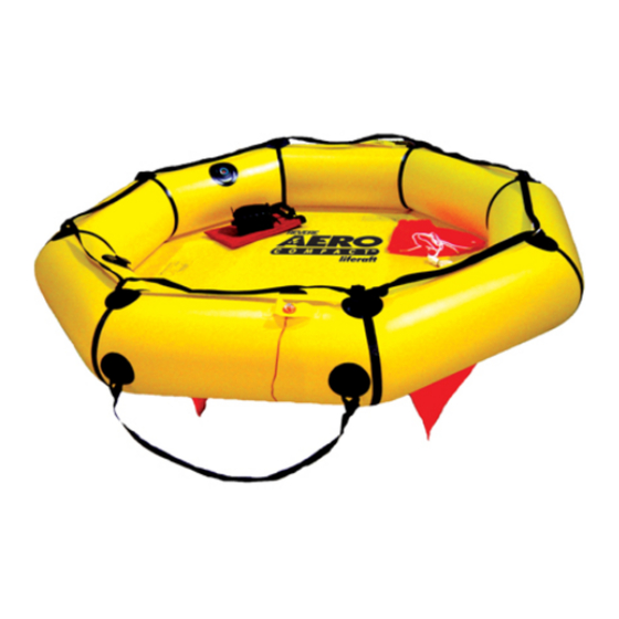
The Aero Compact liferaft’s self-inflation system is initiated manually and is stored in a valise for rapid, easy access by passengers and crew in the event of an emergency. Note: Revere Aero Compact liferafts are emergency life-saving devices and are not intended for any other use. Warning: Revere Aero Compact liferafts are NOT for offshore use. - Page 30 FIGURE 1 – AERO COMPACT (4 person capacity shown. Description comparable to 2 person capacity) Feb 25/11 9105 2 - 4...
-
Page 31: Description
The Aero Compact 4 person raft is composed of one large independent buoyancy tube, a single layer floor, 2 ballast pockets, a righting handle, and a boarding stirrup. The Aero Compact 2 person is composed of one large independent buoyancy tube, a single layer floor, and 2 ballast pockets. -
Page 32: Detail
DETAIL Standard Equipment The Aero Compact Liferafts are equipped with the following items and features (Fig. 1): Painterline/Inflation Lanyard Pulling on the 22ft. (6.7m) inflation lanyard (IPL Fig. 1, Item 70) will activate the inflation system and begin raft deployment in 2 and 4 person liferafts. It can be used as a mooring line after activation. - Page 33 Ballast Pockets Designed to fill with water, they improve raft stability and increase resistance to capsizing. Bailer Used for the removal of excess water from the interior of the raft. 10. Handpump Provided to top-off the buoyancy tubes in the event of a puncture or leak. 11.
- Page 34 FIGURE 2 – VALISE Feb 25/11 9105 2 - 8...
- Page 35 FIGURE 3 – GAS INFLATION SYSTEM Feb 25/11 9105 2 - 9...
-
Page 36: Inflation System
Cylinder Valve Inflation Test (for AC4 only): Every 5 years after date of purchase Tube Operating Pressure Minimum: 1.5 psi Nominal: 2.0 psi Maximum: 3.0 psi Tube Burst Pressure +10 psi Inflation System Aero Compact 2 and 4 Person 327-061 Cylinder, DOT3AL1800, 61 cu. in. Feb 25/11 9105 2 - 10... - Page 37 L in. x W in. x H in. (canopy H) RAFT PART No. L in. x W in. x H in. (kg) (cm) (cm) Aero Compact 2 14.0 x 9.0 x 5.0 53.29 x 53.29 x 8.5 13.0 AC2V (35.56 x 22.86 x 12.70) (136.12 x 136.12 x 21.59)
- Page 38 FIGURE 4 – RAFT DIMENSIONS Feb 25/11 9105 2 - 12...
-
Page 39: Operation
OPERATION It is CRITICAL that the valise is not thrown overboard without FIRST having been secured to a strong point on the aircraft. If this instruction is not observed, the valise may be lost, and/or personnel may be pulled overboard with it. Caution: DO NOT attempt to unpack and inflate the liferaft in the cabin of the aircraft;... - Page 40 FIGURE 5 - DEPLOYMENT Feb 25/11 9105 2 - 14...
- Page 41 FIGURE 6 – CANOPY ATTACHMENT Feb 25/11 9105 2 - 15...
- Page 42 THIS PAGE INTENTIONALLY LEFT BLANK Feb 25/11 9105 2 - 16...
-
Page 43: Disassembly
DISASSEMBLY General Procedures Feb 25/11 9105 3 - 1... - Page 44 THIS PAGE INTENTIONALLY LEFT BLANK Feb 25/11 9105 3 - 2...
- Page 45 GENERAL It will be necessary at normal service and overhaul periods (See Chapter 2 – Data) to remove the packed liferaft from the aircraft. Ensure the working area is clean and dry, free from sharp projections, and large enough to fit the liferaft. The work surface should be smooth, preferably constructed of linoleum or PVC covering.
- Page 46 THIS PAGE INTENTIONALLY LEFT BLANK Feb 25/11 9105 3 - 4...
- Page 47 PROCEDURES Remove the packed liferaft in its valise from the aircraft. Caution: Do not pull or jerk the inflation lanyard as this may cause operation of the inflation system. Inadvertent activation of the inflation system may cause personal injury or damage to raft components. Remove the liferaft from the valise as follows: Pull open the fasteners on the valise.
- Page 48 FIGURE 1 – DISCONNECTING INFLATION HANDLE (Shown below with Aero Compact 4) FIGURE 2 – DISCONNECTING THE CABLE LOOP Feb 25/11 9105 3 - 6...
- Page 49 FIGURE 3 – DISCONNECTING THE CYLINDER NECK LOOP Feb 25/11 9105 3 - 7...
- Page 50 FIGURE 4 – UNFOLD RAFT/DISENGAGE THE CYLINDER Feb 25/11 9105 3 - 8...
-
Page 51: Testing And Fault Isolation
TESTING AND FAULT ISOLATION General Test Record Chart Preparation Leakage Test Procedures General Inflatable Chambers a. Arch Tube Function Tests General Light Topping-Off Valves Pressure Relief Valves Inlet Check Valves Gas Cylinder and Inflation Valve Cylinder Valve Inflation Test Fault Isolation/Troubleshooting Feb 25/11 9105 4 - 1... - Page 52 THIS PAGE INTENTIONALLY LEFT BLANK Feb 25/11 9105 4 - 2...
-
Page 53: General
GENERAL This section contains instructions for minimum performance testing of the Aero Compact Liferafts. The performance test provides a functional equipment check to establish the ability of the systems and components to perform required design function or before the reinstallation of rafts removed from service. - Page 54 THIS PAGE INTENTIONALLY LEFT BLANK Feb 25/11 9105 4 - 4...
-
Page 55: Test Record Chart
TEST RECORD CHART Keep records of ALL inflation tests. Make blank copies of this form and fill out charts when needed. LEAKAGE TEST RECORD – AERO COMPACT LIFERAFT TYPE No. SERIAL No. INSPECTED BY: CHECKED BY: PACK LIFERAFTS WITHIN 48 HOURS OF TEST, UNLESS STORED UNDER APPROVED CONDITIONS RE-TEST if not operationally packed within 30 days of test Date __________ Date __________... - Page 56 THIS PAGE INTENTIONALLY LEFT BLANK Feb 25/11 9105 4 - 6...
-
Page 57: Preparation
PREPARATION Keep record of ALL inflation tests. Copies of Test Record Charts are provided in the previous section. Make blank copies and store at the end of the Section. Protect liferafts from draughts and direct sunlight as temperature affects pressure. Keep at hand a solution of mild liquid soap (NOT detergent) and water, and a plentiful supply of clean, dry, lint-free cloth. - Page 58 THIS PAGE INTENTIONALLY LEFT BLANK Feb 25/11 9105 4 - 8...
-
Page 59: Leakage Test Procedures
LEAKAGE TEST PROCEDURES GENERAL The Aero Compact’s main buoyancy chamber will be tested for leaks. All test results should be recorded on the Aero Compact Test Record Chart (See Table A). INFLATABLE CHAMBERS (AIR HOLDING TEST) Using an inflation tool (Part No. 41128-101) and clean, dry shop air, inflate the buoyancy chamber to until the pressure relief valve (PRV) opens. - Page 60 10. Check the floor for rips or tears. If a rip is located, please refer to Chapter 7 – Repair. 11. Once the repairs are completed, retest failed chamber. 12. If the chamber passes its air retention test or if repairs have been made, please refer to Chapter 8 –...
- Page 61 Refer to Table B for correction quantities due to changes in barometric pressure or temperature over the test period. BUOYANCY TUBES - HIGH PRESSURE Change in Barometric Pressure, P (inHg) Raft Tube Pressure Correction (psi) -.30 -.1470 -.25 -.1225 -.20 -.0980 -.15 -.0735...
- Page 62 BUOYANCY TUBES - HIGH PRESSURE Change in Temperature (°F) Raft Tube Pressure Correction (psi) -10° +.31 -9° +.28 -8° +.25 -7° +.22 -6° +.19 -5° +.16 -4° +.12 -3° +.09 -2° +.06 -1° +.03 0° +1° -.03 +2° -.06 +3° -.09 +4°...
- Page 63 FIGURE 1 – DIGITAL MANOMETER Feb 25/11 9105 4 - 13...
-
Page 64: Arch Tube
Arch Tube To test the arch tube’s inflatable cell for leaks, inflate the arch tube orally until the cell becomes firm. To inflate, flip the replaceable black dust cap off from the top of the red oral tube. Either blow air into the oral tube (See Figure 2) until the arch tube is firm or first fill the arch tube halfway up with compressed air at a low pressure (<10psig) and top off by blowing into the oral tube. -
Page 65: Function Tests
FUNCTION TESTS GENERAL A full function test is not required for normal service. The following items listed will need to be assessed for proper operation and restored if they are non-functional. Refer to Chapter 7 – Repair for repair/replacement instructions for failed components. LIGHT Check the unit expiration date. -
Page 66: Inlet Check Valves
INLET CHECK VALVE Using clean, dry shop air, inflate the compartment to 2.0 psig. Spray a solution of soapy water on top of the valve. Apply solution slowly to generate the least amount of bubbles possible. Monitor and check for generation of new bubbles. The inlet check valves should be airtight and not allow new bubbles to form. -
Page 67: Cylinder Valve Inflation Test
CYLINDER VALVE INFLATION TEST Note: Do not perform the Cylinder Valve Inflation Test with the cylinder still attached to the raft. Remove cylinder from raft (See Chapter 3 – Disassembly). Install diffuser caps onto the inflation valve. Check the weight of the cylinder to make sure no leaks have occurred. Place cylinder into a vise and tighten down. -
Page 68: Fault Isolation/Troubleshooting
FAULT ISOLATION The table below is given to facilitate the locations of troubles in the event of malfunction during the function test, their probable causes, and corrective action. In addition to using this table, visually check the liferaft and equipment for evidence of damage or signs of failure. Fault Probable Cause Corrective Action... -
Page 69: Cleaning
CLEANING General Procedures Liferafts Valise Feb 25/11 9105 5 - 1... - Page 70 THIS PAGE INTENTIONALLY LEFT BLANK Feb 25/11 9105 5 - 2...
- Page 71 GENERAL This section contains instructions on cleaning the Aero Compact Liferafts. When necessary, periodic inspection and cleaning deemed should be performed. The working area must be free from chemicals, corrosives, and solvents. CLEANING MATERIALS Caution: Use only cleaning agents used in Table A. ITEM No.
- Page 72 THIS PAGE INTENTIONALLY LEFT BLANK Feb 25/11 9105 5 - 4...
- Page 73 PROCEDURES Warning: All solvents: Flammable; Keep away from naked lights. Use solvents only in a well ventilated atmosphere. Do not splash into eyes and avoid breathing in the vapors. Use a barrier cream on hands and wash them after using solvents. Liferafts Wash the liferaft with a solution of mild liquid soap (Item 1) and water.
- Page 74 THIS PAGE INTENTIONALLY LEFT BLANK Feb 25/11 9105 5 - 6...
-
Page 75: Service Inspection And Check
SERVICE INSPECTION AND CHECK General Gas Inflation System Valise Pack Feb 25/11 9105 6 - 1... - Page 76 THIS PAGE INTENTIONALLY LEFT BLANK Feb 25/11 9105 6 - 2...
- Page 77 GENERAL The liferaft is to be inspected two (2) years after the date of manufacture and annually after the initial inspection. This will insure that the inflatable chamber will maintain the specified pressure, that the inflation system functions efficiently, and that all components and associated equipment are maintained in a serviceable condition.
- Page 78 THIS PAGE INTENTIONALLY LEFT BLANK Feb 25/11 9105 6 - 4...
- Page 79 GAS INFLATION SYSTEM Warning: The charged gas cylinder can become a lethal projectile if discharged to atmosphere when not fitted with a cap. Always fit a recoil cap to a cylinder valve outlet when handling a fully charged cylinder. Inspect non-return valves for visual defects and security. Weigh the cylinder (minus the diffuser caps) and check it against the weight marked on the cylinder.
- Page 80 THIS PAGE INTENTIONALLY LEFT BLANK Feb 25/11 9105 6 - 6...
- Page 81 VALISE PACKS Inspect valise for: Cleanliness, freedom from splits, tears, or other obvious signs of damage. Legibility of all marks and labels. Feb 25/11 9105 6 - 7...
- Page 82 THIS PAGE INTENTIONALLY LEFT BLANK Feb 25/11 9105 6 - 8...
-
Page 83: Repair
REPAIR General Non-Repairable Rafts Repairable Rafts Procedures Adhesive Preparation of Coasted Surfaces Applying Adhesive Repairing Torn Areas Patches Applying Patches Repair Limits for External Patches Component Repair Pressure Relief Valve Topping-Off Valve Inlet Check Valve Inflation Valve Canopy Feb 25/11 9105 7 - 1... - Page 84 THIS PAGE IS INTENTIONALLY LEFT BLANK Feb 25/11 9105 7 - 2...
-
Page 85: General
Sewing repairs to the valise. If repairs beyond the limits of the conditions described in previous statements, it is recommended that the raft be returned to Revere Supply Co. Inc. Clean all repaired disassembled parts prior to re-assembly according to procedures described in the Cleaning Section of this manual. - Page 86 THIS PAGE INTENTIONALLY LEFT BLANK Feb 25/11 9105 7 - 4...
-
Page 87: Procedures
The adhesive to be used for repairs is supplied in a 4oz. can with brush top. (Part No. 306-004) Only the specified adhesive shall be used for the repair of liferafts manufactured by Revere Supply Co., Inc. Using unspecified adhesives may have unexpected side effects resulting in premature failure. -
Page 88: Preparation Of Coasted Surfaces
PREPARATION OF COATED SURFACES Polyurethane-proofed surfaces Caution: VERY IMPORTANT – The heavy duty polyurethane coating on the material used for the buoyancy chambers/floor must have the surface contamination completely removed by thoroughly cleaning the coated surfaces with solvent MEK (Methyl Ethyl Ketone). Petroleum or Toluene type cleaning solvents are ineffective on this material and must not be used. -
Page 89: Applying Adhesive
APPLYING ADHESIVE For the purposes of repair the words ‘tacky’ and aggressive tack are defined as follows: (1). When the word ‘tacky’ is used, it means that if the fingers are lightly dragged across the adhesive, it tends to pull off the base fabric or the previous coat. (2). -
Page 90: Repairing Torn Areas
REPAIRING TORN AREAS While many of the seams in the Aero Compact Liferafts are glued with a strong adhesive, others are of welded construction. Once welded, these seams cannot be opened. A correctly welded seam is such that no discernable interface between the two polyurethane surfaces will remain. -
Page 91: Repair Limits For External Patches
Revere Supply Co., Inc. cannot offer partial or complete panel/tube replacement. It will be necessary to replace the liferaft should significant damage occur to the panels or tubes. Repair Limits for External Patches Patching of the buoyancy tubes is permitted, but there must not be more than 10 patches per panel, and the area of the 10 patches together must not exceed 25% of the panel area. -
Page 92: Component Repair
COMPONENT REPAIR Pressure Release Valve Dismantling the pressure relief valve is not permitted. Unscrew the valve and replace. Topping-Off Valve Unscrew the valve and replace. Inlet Check Valves Unscrew the valves and replace. Inflation Valve See Chapter 8 – Assembly for inflation valve rebuilding. Canopy The canopy is a non-repairable item. - Page 93 FIGURE 1 – PATCHES AND TAPE APPLICATION Feb 25/11 9105 7 - 11...
- Page 94 FIGURE 2 – PATCH APPLICATION OVER SEAM Feb 25/11 9105 7 - 12...
- Page 95 FIGURE 2 – PATCH APPLICATION OVER SEAM Keep records of all repairs. Make blank copies of this form and fill out charts when needed. REPAIR RECORD LIFERAFT TYPE No. SERIAL No. REPAIRS REQUIRED PART DAMAGE FORM OF REPAIR INSP. BY Buoyancy Tube Floor Inflation Equipment...
- Page 96 THIS PAGE INTENTIONALLY LEFT BLANK Feb 25/11 9105 7 - 14...
-
Page 97: Assembly And Packing
ASSEMBLY AND PACKING General Component Setup A. Handpump and Bailer B. Sea Anchor C. Painterline D. Light E. Knife F. Inflation Valve/Cylinder G. Canopy Inflation Valve Disassembly & Rebuilding Process Procedures Equipment Pack Feb 25/11 9105 8 - 1... - Page 98 THIS PAGE INTENTIONALLY LEFT BLANK Feb 25/11 9105 8 - 2...
- Page 99 GENERAL This section describes the proper procedures for assembly and repacking of all Aero Compact Liferafts. Before beginning the assembly, the work area must be clean, dry, and free from sharp projections. Work should be done on a smooth surface, preferably linoleum. The raft should be completely deflated with dust covers inserted into topping off valves.
- Page 100 THIS PAGE INTENTIONALLY LEFT BLANK Feb 25/11 9105 8 - 4...
- Page 101 COMPONENT SETUP COMPONENT PREPARATION Warning: Take care when using any electric tooling. Be sure to protect your eyes and hands when performing any of these procedures. Refer to tool manufacturer’s manuals on proper use of their equipment before performing any of these outlined procedures.
- Page 102 Inflation Valve/Cylinder Install cylinder and valve assembly into cylinder holder. Screw swivel nut of inlet check valve to the outlet fitting of cylinder valve. Torque to 14-15 lbf ft. Place Valve Foam Cover (IPL Fig. 1, Items 180) over inflation valve and tape down securely. (See Fig. 2F) Canopy Completely deflate the arch-tube (IPL Fig.
- Page 103 FIGURE 2C – FOLDING SEA ANCHOR FIGURE 2D – PAINTERLINE PREPARATION Feb 25/11 9105 8 - 7...
- Page 104 FIGURE 2E – PREPARING LIGHT FIGURE 2F – INFLATION VALVE/CYLINDER PREPARATION Feb 25/11 9105 8 - 8...
- Page 105 INFLATION VALVE DISASSEMBLY & REBUILDING PROCESS 41115 Inflation Valve 1.1 Torque Settings 1.2 Removal of Inflation Valve from Cylinder 1.3 41115 Disassembly / Rebuilding 1.4 41115 Reassembly / Rebuilding 1.5 41115 Inflation Valve Installation 1.6 Charging Cylinder 1.7 CO Leak Test Refer to Chapter 11 - Illustrated Parts List Figure 4 for breakdown of Inflation Valve 41115 components.
- Page 106 1.1 Torque Settings The settings listed in table below list the required torque settings for the 41115 Series inflation system. Refer to this table when tightening inflation system components that require a specific setting. Tighten to the minimum setting in the specified range first. If leakage occurs, discharge the assembly and tighten to the maximum setting.
- Page 107 1.3.2 Inflation Valve Illustrated Disassembly / Rebuilding Process Note: All components can be removed using a socket wrench, but most will only require a standard or open-ended wrench. If using a socket (A 6pt socket is recommended to minimize dings to the hex edges), rotate the fitting to be removed to this cut-out.
- Page 108 Step 4: Remove the Fill Fitting Poppet (IPL Fig. 4, Item 40) and Washer (IPL Fig. 4, Item 70) from Fill Fitting Housing. Step 5: Using a socket wrench, remove the Safety Disk Retainer (IPL Fig. 4, Item 110), Disk, and Washer (IPL Fig.
- Page 109 Step 8: Use an O-Ring pick to remove the O-Rings from: Fill Fitting Cap Safety Disk Retainer Piston Step 9: Inspect all components for damage and corrosion, replace as necessary. Clean all components of old grease and dirt, use cotton swabs to clean ports.
- Page 110 1.4 Inflation Valve Reassembly Prepare the Inflation Valve for rebuilding. Items List: Rebuild Kit (Part No. 41120-101) DC-111 O-Ring Lubricant Wrenches and Sockets Torque Wrench Sprayon S00204 Lubricant Uniflor 8132 Lubricant Loctite 1.4.1 Only organizations that are equipped with the latest technical data, tools and fixtures are permitted to perform inflation valve rebuilding activities.
- Page 111 1.4.2 Inflation Valve Illustrated Reassembly / Rebuilding Process Step 1: After applying lubrication to the O-rings, install them in the Fill Fitting Cap, and Safety Disk Retainer as necessary. Step 2: Being sure the Safety Pin hole is facing upwards, install the Piston Housing (IPL Fig. 4, Item 140) and Pull Lanyard (IPL Fig.
- Page 112 Step 5: Install the Safety Disk (IPL Fig. 4, Item 100). Step 6: Replace Safety Disk Retainer (IPL Fig. 4, Item 110) and torque to the settings in Table A. Step 7: Install Sealing Washer (IPL Fig. 4, Item 70) into Fill Fitting Cavity.
- Page 113 Step 9: Install Fill Fitting Cap (IPL Fig. 4, Item 160) and hand tighten. Step 10: Apply thread sealant Loctite to Outlet Fitting before installing. Torque according to settings listed in Table A. Feb 25/11 9105 8 - 17...
- Page 114 1.5 Inflation Valve Installation - 41115 Figure 1.5 Inflation Valve Installation - 41115 1.5.1 Inspect inflation valve threads for cleanliness and damage. 1.5.2 Apply a thin film of DC-111 lubricant to inflation valve O-ring. 1.5.3 Inspect cylinder threads and O-ring Groove for cleanliness and damage. Carefully screw Inflation Valve into Cylinder.
- Page 115 1.6 Charging the Cylinder 1.6.1 The inflation system is charged with Carbon Dioxide. Cylinders must only be charged by properly trained technicians. 1.6.2 Verify proper installation of Inflation Valve, install Diffuser Caps on outlet connectors. 1.6.3 Remove Fill Fitting Cap. 1.6.4 Above figures show a picture of the "Charge Adaptor", proper installation of the charging hose using the Charge Adaptor and Quick Disconnect, and a simple Charging Station.
- Page 116 After the cylinder is charged to the correct weight (See Table B) and is torque to the correct value (See Table A), a leak test must be administered. 1.7.1 Using Revere Leak Test Solution (Part No. 50-CO2-LEAK), pour approximately 2oz. into a 4in. X 6in. poly bag to enclose the entire valve and neck of cylinder. Use 1in. masking tape (or equivalent), secure the poly bag over the neck of the cylinder.
- Page 117 PROCEDURE Note: It is recommended that the liferaft be packed by two men. Place the liferaft on a platform or in an open area with enough room to maneuver the liferaft and valise during packing. Locate the topping-off (inflate/deflate) valve. Using a vacuum adapter (Part No. 41129-101) connected to a vacuum source, evacuate all air from the compartment.
- Page 118 140). Run the cord through the two holes in both the valise and the sachet and secure with three (3) bowline knots. Trim off any remaining cord. 16. For the Aero Compact 2 only, run the handle end marked “painterline” over top of the valise. Secure handle end to side of valise.
- Page 119 FIGURE 3 – TOPPING-OFF (INFLATE/DEFLATE) VALVE FIGURE 4 – ATTACHING THE CYLINDER Feb 25/11 9105 8 - 23...
- Page 120 FIGURE 5 – STORAGE OF COMPONENTS Feb 25/11 9105 8 - 24...
- Page 121 FIGURE 6A – AC2V FOLDING DIAGRAM STEP 1 Note: Refer to Chapter 2 – Description, Table A for the L x W x H dimensions shown in the following folding diagrams. Feb 25/11 9105 8 - 25...
- Page 122 FIGURE 6B – AC2V FOLDING DIAGRAM STEP 2 Feb 25/11 9105 8 - 26...
- Page 123 FIGURE 6C – AC2V FOLDING DIAGRAM STEP 3 Feb 25/11 9105 8 - 27...
- Page 124 FIGURE 6D – AC2V FOLDING DIAGRAM STEP 4 FIGURE 6E – AC2V FOLDING DIAGRAM STEP 5 Feb 25/11 9105 8 - 28...
- Page 125 FIGURE 6F – AC2V FOLDING DIAGRAM STEP 6 FIGURE 6G – AC2V FOLDING DIAGRAM STEP 7 Feb 25/11 9105 8 - 29...
- Page 126 FIGURE 6H – AC2V FOLDING DIAGRAM CC4 STEP 8 Feb 25/11 9105 8 - 30...
- Page 127 FIGURE 7A – AC4V FOLDING DIAGRAM STEP 1 Feb 25/11 9105 8 - 31...
- Page 128 FIGURE 7B – AC4V FOLDING DIAGRAM STEP 2 Feb 25/11 9105 8 - 32...
- Page 129 FIGURE 7C – AC4V FOLDING DIAGRAM STEP 3 Feb 25/11 9105 8 - 33...
- Page 130 FIGURE 7D – AC4V FOLDING DIAGRAM STEP 4 Feb 25/11 9105 8 - 34...
- Page 131 FIGURE 7E – AC4V FOLDING DIAGRAM STEP 5 Feb 25/11 9105 8 - 35...
- Page 132 FIGURE 7F – AC4V FOLDING DIAGRAM STEP 6 Feb 25/11 9105 8 - 36...
- Page 133 FIGURE 7G – AC4V FOLDING DIAGRAM STEP 7 Feb 25/11 9105 8 - 37...
- Page 134 FIGURE 7H – AC4V FOLDING DIAGRAM STEP 8 FIGURE 7I – AC4V FOLDING DIAGRAM STEP 9 Feb 25/11 9105 8 - 38...
- Page 135 FIGURE 7J – CC6 FOLDING DIAGRAM STEP 10 FIGURE 7K – AC4V FOLDING DIAGRAM STEP 11 Feb 25/11 9105 8 - 39...
- Page 136 FIGURE 7L – CC6 FOLDING DIAGRAM STEP 12 Feb 25/11 9105 8 - 40...
- Page 137 FIGURE 8 – PAINTERLINE LOOPS FIGURE 9 - ATTACHMENT OF CYLINDER NECK LOOP Feb 25/11 9105 8 - 41...
- Page 138 FIGURE 10 – ATTACHMENT OF CABLE LOOP Feb 25/11 9105 8 - 42...
- Page 139 FIGURE 11 – ATTACHMENT OF PAINTERLINE SACHET DETAIL A - ATTACHMENT OF PAINTERLINE LOOP Feb 25/11 9105 8 - 43...
- Page 140 THIS PAGE INTENTIONALLY LEFT BLANK Feb 25/11 9105 8 - 44...
- Page 141 EQUIPMENT PACK Components Part No. Item Standard Standard Plus Deluxe Survival Kit Valise Ass’y 41202-101 Canopy Ass’y 41154-101 Fishing Kit 95-301-061 First Aid Kit 51120-101 Flashlight with Batteries 50-REVRN4 Food Rations 90-S0-FB400/REV Paddles 301-019 Canopy Arch Ass’y 41159-101 Compass 50-331 Emergency Blanket 95-301-038CRD Raft Repair Kit...
- Page 142 Canopy Placement in all Kits Each survival kit assembly will be packed with (1) folded canopy (Item 41154-101) and (1) folded canopy arch (Item 41159-101) prior to packaging other items. Fold ends of canopy neatly inside valise after remaining items have been properly packing valise. Packed kit should be placed and sealed in polybag (Item 336-003-2030) before placing in valise.
- Page 143 Standard Kit Pack Feb 25/11 9105 8 - 47...
- Page 144 Standard Plus Kit Pack Feb 25/11 9105 8 - 48...
- Page 145 Deluxe Kit Pack Feb 25/11 9105 8 - 49...
- Page 146 THIS PAGE INTENTIONALLY LEFT BLANK Feb 25/11 9105 8 - 50...
-
Page 147: Storage
STORAGE General Feb 25/11 9105 9 - 1... - Page 148 THIS PAGE INTENTIONALLY LEFT BLANK Feb 25/11 9105 9 - 2...
- Page 149 GENERAL This section describes the proper storage procedures for Aero Compact Liferafts. Rafts should be stowed where they can easily be reached in an emergency. Stow in a compartment with at least 1” (25mm) clearance all around for easy removal. All rafts should be stowed in a clean, dry, contaminant free area away from any heat source.
- Page 150 THIS PAGE INTENTIONALLY LEFT BLANK Feb 25/11 9105 9 - 4...
- Page 151 TOOL, EQUIPMENT, AND MATERIALS General Breakdown Feb 25/11 9105 10 - 1...
- Page 152 THIS PAGE INTENTIONALLY LEFT BLANK Feb 25/11 9105 10 - 2...
- Page 153 GENERAL This section contains a listing of all tools, equipment, and materials used to service the Aero Compact Liferafts. To keep your tools in proper working order, take care of them by: Inspecting and adjusting daily Replacing worn or broken parts Cleaning and lubricating weekly Always keep work areas uncluttered and well lighted.
- Page 154 THIS PAGE INTENTIONALLY LEFT BLANK Feb 25/11 9105 10 - 4...
- Page 155 TOOL/EQUIPMENT/MATERIAL PART NUMBER SECTION 3 – DISASSEMBLY Wrench Diffuser Cap, -5 301-017 SECTION 4 – TESTING AND FAULT ISOLATION Manometer (0-10 psig)) Thermometer (hang on manometer) Rubber Tubing (1/8in. x 3/8in. i/d x 1/2in. o/d) (3m of 9mm i/d, 12mm o/d) for manometer connection Inflation Tool w/ Ball Valve, Quick-Connect End 41128-101 Deflation Tool, 3/8in.
- Page 156 Crow Foot, 1 1/2in. Wrenches (9/16in., 5.8in.) Ratchet drives (3/8in., 1/2in.) 3/16in. Hex Wrench Valve Overhaul Kit 41120-101 Socket Wrenches (3/4in., 1in.) 50-CO2-LEAK Revere Leak Test Solution SECTION 9 – STORAGE 301-017 Diffuser Cap, -5 Feb 25/11 9105 10 - 6...
- Page 157 IMAGES Bleed Down Tool Part # 338-007 Inflation Tool w/ Ball Valve, Quick Connect End Part # 41128-101 Deflation Tool Part # 41129-101 Socket, 1-3/8in. Part # 338-008 Feb 25/11 9105 10 - 7...
- Page 158 Quick Disconnect Valve Charging Stem Part # 338-005 Quick Disconnect Valve Charging Body Part # 338-006 Feb 25/11 9105 10 - 8...
- Page 159 ILLUSTRATED PARTS LIST (IPL) Introduction Numerical Parts List Detailed Parts List Image List Feb 25/11 9105 11 - 1...
- Page 160 THIS PAGE INTENTIONALLY LEFT BLANK Feb 25/11 9105 11 - 2...
- Page 161 Items with the same part number but different quantities per assembly will be assigned a suffix as a variant of the original part number, e.g. 10 and 10A. PART NUMBERING Revere Supply Co., Inc. part number. ILLUSTRATIONS A view of each assembly, exploded as necessary to show the component parts is provided. Each illustration is assigned a figure number.
- Page 162 NOMENCLATURE CONTINUED ‘Replaced By’ means that the part in the part number column is replaced by and is interchangeable with the part number shown in the notation. ‘Replaces’ means that the part in the part number column replaces and is interchangeable with the part number shown in the notation.
- Page 163 Image List at the end of this section. 10. VENDOR CODES AND ADDRESSES A part manufactured by a different company other than Revere Supply is identified by a Vendor Code, following the nomenclature. Vendor Codes are in accordance with the Federal Supply Codes for Manufacturers for American Vendors, and NATO Codes for UK Vendors.
- Page 164 THIS PAGE INTENTIONALLY LEFT BLANK Feb 25/11 9105 11 - 6...
- Page 165 NUMERICAL PARTS LIST No equivalent substitutes are to be used for listed items without the prior written consent of Revere Supply Co., Inc. Revere Supply Co., Inc. will not accept responsibility for any equipment malfunction where unauthorized substitutions have been used.
- Page 166 FIG – ITEM No. PART No. UNITS PER ASSY. AC2V AC4V 1-1A AC4VP 1-1B AC4V-K 1-1C AC4V-K2 1-1D AC4V-K3 1-1E 301-001 1-170 301-028 1-200 313-005-720 1-250 319-001 1-90 324-003 1-50 325-002 1-40 326-006 3-30 326-033 1-30 327-061 3-20 41009-101 2-10 41013-103 2-20 41017-101...
- Page 167 FIG – ITEM No. PART No. UNITS PER ASSY. 41115-4 4-40 41115-5 4-50 41115-6 4-60 41115-7 4-70 41115-8 4-80 41115-9 4-90 41115-10 4-100 41115-11 4-110 41115-12 4-120 41115-13 4-130 41115-14 4-140 41115-15 4-150 41115-16 4-160 41115-17 4-170 41115-18 4-180 41115-19 4-190 41115-20 4-200...
- Page 168 THIS PAGE INTENTIONALLY LEFT BLANK Feb 25/11 9105 11 - 10...
- Page 169 DETAILED PARTS LIST No equivalent substitutes are to be used for listed items without the prior written consent of Revere Supply Co., Inc. Revere Supply Co., Inc. will not accept responsibility for any equipment malfunction where unauthorized substitutions have been used.
- Page 170 FIGURE 1 – LIFE RAFT ASSEMBLY Feb 25/11 9105 11 - 12...
- Page 171 Hull Assy., Aero Compact 2 (Not Procurable) 41094-101 Hull Assy., Aero Compact 4 BCDEF (Not Procurable) 41114-105 Cylinder & Valve Assy. Aero Compact 2 (See Fig. 3) 41114-107 Cylinder & Valve Assy. BCDEF Aero Compact 4 (See Fig. 3) 326-033 Topping-Off Valve 325-002...
- Page 172 ASSY. –160 Cord, Nylon, Braided, 1/16” 41084-15 Black, 8” Long 301-001 Handpump Assy. w/ Adapter –180 41206-101 Valve Cover ABCDEF Aero Compact 2 & 4 –190 Owner’s Manual 41186-1 –200 301-028 Key Ring BCDEF –210 41169-101 Canopy Buckle Strap BCDEF...
- Page 173 THIS PAGE INTENTIONALLY LEFT BLANK Feb 25/11 9105 11 - 15...
- Page 174 FIGURE 2 – HULL ASSEMBLY Feb 25/11 9105 11 - 16...
- Page 175 UNITS FIG. No. EFF. IMAGE PART No. NOMENCLATURE ITEM CODE ASSY. Fig. 2 –1 41092-101 Hull Assy., Aero Compact 2 –1A 41094-101 Hull Assy., Aero Compact 4 41009-101 Knife Pocket 41013-103 Lifeline/Graspline Loop Patch 41017-101 Light Holder 41029-101 Battery Holder...
- Page 176 FIGURE 3 – CYLINDER & VALVE ASSEMBLY Feb 25/11 9105 11 - 18...
- Page 177 NOMENCLATURE ITEM CODE ASSY. Fig. 3 –1 41114-105 Cylinder & Valve Assy. (CO Aero Compact 2 –1A 41114-107 Cylinder & Valve Assy. (CO Aero Compact 4 41115-101 Inflation Valve, Model 41115 (See Figure 4 for breakdown) Cylinder, DOT3AL1800, 61cu. in.
- Page 178 FIGURE 4 – INFLATION VALVE ASSEMBLY M41115 Feb 25/11 9105 11 - 20...
- Page 179 UNITS FIG. No. EFF. IMAGE PART No. NOMENCLATURE ITEM CODE ASSY. Fig. 4 41115-101 Inflation Valve, Model 41115 41115-1 Body Assembly 41115-2 O-Ring (-210)* 41115-3 I.D. Decal 41115-4 Fill Fitting Poppet* 41115-5 O-Ring (006)* 41115-6 Fill Fitting Housing 41115-7 Washer Sealing* 41115-8 Washer Seal* 41115-9...
- Page 180 THIS PAGE INTENTIONALLY LEFT BLANK Feb 25/11 9105 11 - 22...
- Page 181 IMAGE LIST ITEM # 1 Topping Off Valve Part # 326-033 FIG-ITEM QTY. 1-30 ITEM # 2 Fixed Inlet Check, -5 Female Part # 325-002 FIG-ITEM QTY. 1-40 ITEM # 3 Pressure Release Valve Medium Flow Part # 324-003 FIG-ITEM QTY.
- Page 182 ITEM # 5 PFD Light Part # 319-001 FIG-ITEM QTY. 1-90 ITEM # 6 Knife, Low Profile Part # 41193-101 FIG-ITEM QTY. 1-100 ITEM # 7 Sea Anchor Part # 41027-101 FIG-ITEM QTY. 1-110 ITEM # 8 Bailing Bucket Assembly Part # 41065-101 FIG-ITEM QTY.
- Page 183 ITEM # 9 Handpump Assembly with Adapter Part # 301-001 FIG-ITEM QTY. 1-170 ITEM # 10 Valve Cover AC2 & AC4 Part # 41206-101 FIG-ITEM QTY. 1-180 ITEM # 11 Key Ring Part # 301-028 FIG-ITEM QTY. 1-200 ITEM # 12 Canopy Buckle Strap Part # 41169-101 FIG-ITEM...
- Page 184 ITEM # 13 Handle Wrap Part # 41207-101 FIG-ITEM QTY. 1-240 ITEM # 14 Inflation Valve, Model 41115 Part # 41115-101 FIG-ITEM QTY. 3-10A ITEM # 15 Cord, Nylon, 1/16”, Black Part # 313-004 Sold per yard (min. 10yrds) For use with internal straps FIG-ITEM QTY.
- Page 185 A 3-page version of the certificate is provided to every service station. Completion of this form is required at every service. Copies of the form will then be sent to the appropriate group as follows: White: Vessel Canary: Service Station Pink: Revere Supply Co. Inc. Feb 25/11 9105 A - 1...
- Page 186 THIS PAGE INTENTIONALLY LEFT BLANK Feb 25/11 9105 A - 2...
- Page 187 1901 RECREATIONAL LIFERAFT RE-INSPECTION CERTIFICATE This is to certify that this liferaft has been inspected and serviced in accordance with the REVERE SURVIVAL INC. servicing manuals. MODEL: __________________________ SIZE (circle one) 2 4 6 8 S SERIAL NO: ____________________________ DOM: _____/_____/_____ DATE OF PREVIOUS INSP: ______/_____/______DATE OF NEXT INSP: _____/_____/______...
Need help?
Do you have a question about the Aero Compact 2 and is the answer not in the manual?
Questions and answers