Table of Contents
Advertisement
Quick Links
ASSEMBLY INSTRUCTIONS
INSTRUCCIONES DE ENSAMBLAJE
INSTRUCTIONS D'ASSEMBLAGE
MONTAGEANLEITUNGEN
®
RiverRidge
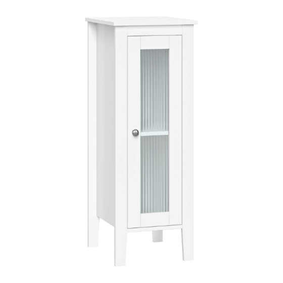
Prescott Single Door Floor Cabinet
®
RiverRidge
Gabinete de piso de una puerta Prescott
®
RiverRidge
Armoire à porte unique Prescott
®
RiverRidge
Eintüriger Vitrinenhalbschrank Prescott
06-162 - White, Blanco, Blanc, Weiß
®
RiverRidge
is a registered trademark of Sourcing Solutions, Inc., Hudson, WI 54016, USA
®
RiverRidge
es una marca comercial registrada de Sourcing Solutions, Inc., Hudson, WI 54016, USA
®
RiverRidge
est une marque déposée de Sourcing Solutions, Inc., Hudson, WI 54016, USA
®
RiverRidge
ist ein eingetragenes Warenzeichen der Sourcing Solutions, Inc. mit Sitz in Hudson, WI 54016, USA
Advertisement
Table of Contents

Related Manuals for RiverRidge Prescott 06-162


Summary of Contents for RiverRidge Prescott 06-162
- Page 1 ASSEMBLY INSTRUCTIONS INSTRUCCIONES DE ENSAMBLAJE INSTRUCTIONS D’ASSEMBLAGE MONTAGEANLEITUNGEN ® RiverRidge Prescott Single Door Floor Cabinet ® RiverRidge Gabinete de piso de una puerta Prescott ® RiverRidge Armoire à porte unique Prescott ® RiverRidge Eintüriger Vitrinenhalbschrank Prescott 06-162 - White, Blanco, Blanc, Weiß...
- Page 2 WARNING ADULT ASSEMBLY REQUIRED: This product requires assembly by an adult because of small parts. Care should be taken in unpacking and assembling this item to keep small parts away from children. During assembly children should be kept away from the product due to possible risk of injury. SERIOUS OR FATAL INJURIES CAN OCCUR FROM FURNITURE TIP-OVER.
- Page 3 ADVERTENCIA REQUIERE QUE UN ADULTO REALICE EL ENSAMBLAJE: Este producto requiere que un adulto lleve a cabo el ensamblaje debido a las piezas pequeñas. Debe tener cuidado al desempacar y ensamblar este artículo para mantener las piezas pequeñas alejadas de los niños. Los niños deben mantenerse alejados del producto durante el ensamblaje debido al posible riesgo de lesiones.
- Page 4 AVERTISSEMENT L’ASSEMBLAGE DOIT ÊTRE EFFECTUÉ PAR UN ADULTE : Ce produit doit être assemblé par un adulte à cause de la présence de petites pièces. Lorsque vous déballez et assemblez cet article, veillez à tenir les petites pièces hors de portée des enfants.
- Page 5 WARNUNG MONTAGE DURCH ERWACHSENE ERFORDERLICH: Dieses Produkt muss wegen der kleinen Teile von einem Erwachsenen zusammengebaut werden. Beim Auspacken und Zusammenbau dieses Artikels ist darauf zu achten, dass Kleinteile von Kindern ferngehalten werden. Während der Montage sollten Kinder wegen möglicher Verletzungsgefahr vom Produkt ferngehalten werden.
-
Page 6: Parts List
PARTS LIST DESCRIPTION Top Board Left Side Board Right Side Board Bottom Board Cross Bar Door Adjustable Shelf Back Board... - Page 7 PARTS LIST PARTS DESCRIPTION 10PCS Wood Dowel Cam Bolt 8PCS Cam Lock 8PCS Screw (4x30mm) Screw (3x10mm) 2PCS Screw (3.5x14mm) 12PCS Hinge 2PCS Machine Screw (4x16mm) Screw (2.5x10mm) 12PCS Screw (4x12mm) Shelf Holder 4PCS Plastic Anchor Screw (4x40mm) Plastic Door Pad Knob Adjustable Anchor Bracket TOOLS NEEDED FOR ASSEMBLY: FLAT &...
- Page 8 STEP 1 Screw 2 cam bolts (B) into cam bolt holes on right side board (3) Screw 2 cam bolts (B) into cam bolt holes on left side board (2) Screw 4 cam bolts (B) into cam bolt holes on top board (1) Attach adjustable anchor bracket (R) to top board (1) by inserting 1 screw (K) through hole on adjustable anchor bracket (R), then tighten to top board (1).
- Page 9 STEP 3 Insert 3 wood dowels (A) into wood dowel holes on left side board (2). Attach bottom board (4) and cross bar (5) to left side board (2) by inserting cam bolts into cam lock holes and wood dowels into wood dowel holes on bottom board (4) and cross bar (5).
- Page 10 STEP 5 Insert 1 screw (D) through hole on cross bar (5), then tighten to top board (1). Attach back board (8) to back of cabinet by inserting 12 screws (J) through holes on back board (8), then tighten to back of cabinet. STEP 6 Attach door (6) to right side board (3) by inserting 8 screws (F) through holes on door hinges (G), then tighten to right side board (3).
- Page 11 STEP 7 OPTION #1 OPTION #2 DRYWALL DRYWALL WOOD STUD SCREW WALL ANCHOR ONLY WITH SCREW Option #1: Securing to Drywall 1. Position cabinet against wall in desired location. Using a pencil, make 1 small mark on wall through hole on adjustable anchor bracket (R). Move cabinet away from wall and screw 1 plastic anchor (M) into wall on pencil mark.
-
Page 12: Care Instructions
ATTENTION ADULTS: Cabinet should be checked periodically for damage or loose screws/parts. Take appropriate action necessary to correct hazards such as tightening of screws and taking any damaged parts away from children. WARNING Please make sure your item is secured to the wall, per assembly instructions. CARE INSTRUCTIONS: Wipe clean with a water dampened cloth. -
Page 13: Lista De Piezas
LISTA DE PIEZAS N.° DESCRIPCIÓN CANT. Tablero superior Tablero lateral izquierdo Tablero derecho Tablero inferior Barra transversal Puerta Repisa ajustable Tablero trasero Pasador de madera Perno de anclaje Pestillo de leva Tornillo (4x30mm) Tornillo (3x10mm) Tornillo (3,5x14mm) Bisagra Tornillo para metales (4x16mm) Tornillo (2,5x10mm) Tornillo (4x12mm) Soporte del estante... - Page 14 PASO 1 1. Atornille 2 pernos de anclaje (B) en los agujeros correspondientes del tablero lateral derecho (3). 2. Atornille 2 pernos de anclaje (B) en los agujeros correspondientes del tablero lateral izquierdo (2). 3. Atornille 4 pernos de anclaje (B) en los agujeros correspondientes del tablero superior (1). 4.
-
Page 15: Instrucciones De Cuidado
PASO 7 Opción n.º 1: Fijar a una pared de yeso 1. Ubique el gabinete contra una pared en el lugar deseado. Con un lápiz, realice 1 marca pequeñas en la pared a través del agujero del soporte de anclaje regulable (R). Aleje el gabinete de la pared y atornille 1 anclaje de plástico (S) en la pared sobre la marca que realizó... -
Page 16: Liste Des Pièces
LISTE DES PIÈCES Nº DESCRIPTION QTÉ Plaque supérieure Plaque latérale gauche Plaque latérale droite Plaque inférieure Barre transversale Porte Étagère réglable Plaque arrière Goujon en bois Vis de came Verrou de came Vis (4x30mm) Vis (3x10mm) Vis (3,5x14mm) Charnière Vis mécanique (4x16mm) Vis (2,5x10mm) Vis (4x12mm) Support d’étagère... - Page 17 ÉTAPE 1 1. Vissez 2 boulons à came (B) dans les trous de boulons à came sur la planche latérale droite (3) 2. Vissez 2 boulons à came (B) dans les trous de boulons à came sur la planche latérale gauche (2) 3.
-
Page 18: Instructions D'entretien
ÉTAPE 6 1. Fixez la porte (6) sur la planche latérale droite (3) en insérant 8 vis (F) dans les trous des charnières, puis en les vissant dans la planche latérale droite (3). 2. Fixez un bouton (Q) sur la porte (6) en insérant 1 vis mécanique (H) dans le trou de la porte (6), puis en la vissant sur le bouton (Q). - Page 19 TEILELISTE BESCHREIBUNG ANZ. Oberstes Brett Linkes Seitenteil Rechtes Seitenteil Unterstes Brett Querleiste Tür Verstellbarer Regalboden Rückwand Holzdübel Korpusverbinder-Bolzen Korpusverbinder-Exzentergehäuse Schraube (4x30mm) Schraube (3x10mm) Schraube (3,5x14mm) Scharnier Maschinenschraube (4x16mm) Schraube (2,5x10mm) Schraube (4x12mm) Regalbodenhalterung Kunststoffdübel Schraube (4x40mm) Plastic Door Pad Knauf Einstellbarer Ankerbügel FÜR DIE MONTAGE BENÖTIGTE WERKZEUGE: FLACH- UND KREUZSCHLITZSCHRAUBENDREHER (NICHT ENTHALTEN).
- Page 20 SCHRITT 1 1. Schrauben Sie 2 Korpusverbinder-Bolzen (B) in die Korpusverbinder-Bolzenbohrungen des rechten Seitenteils (3). 2. Schrauben Sie 2 Korpusverbinder-Bolzen (B) in die Korpusverbinder-Bolzenbohrungen des linken Seitenteils (2). 3. Schrauben Sie 4 Korpusverbinder-Bolzen (B) in die Korpusverbinder-Bolzenbohrungen des obersten Bretts (1). 4.
- Page 21 SCHRITT 6 1. Befestigen Sie die Tür (6) am rechten Seitenteil (3), indem Sie 8 Schrauben (F) durch die Öffnungen der Türscharniere (G) stecken und sie dann am rechten Seitenteil (3) festziehen. 2. Befestigen Sie den Knauf (Q) an der Tür (6), indem Sie 1 Maschinenschraube (H) durch die Bohrung in der Tür (6) stecken und dann am Knauf (Q) festschrauben.
Need help?
Do you have a question about the Prescott 06-162 and is the answer not in the manual?
Questions and answers