Table of Contents
Advertisement
Advertisement
Table of Contents

Related Manuals for Xylem FLYGT MiniCAS II

Summary of Contents for Xylem FLYGT MiniCAS II
- Page 1 Installation, Operation, and Maintenance Manual MiniCAS II...
-
Page 3: Table Of Contents
Table of Contents Table of Contents 1 Introduction and Safety......................2 1.1 Introduction.......................... 2 1.2 Safety terminology and symbols..................2 1.3 User safety..........................3 1.4 Product warranty........................3 1.4.1 Support...........................4 2 Transportation and Storage...................... 5 2.1 Inspect the delivery......................5 3 Product Description........................6 3.1 Product design........................6 3.2 Parts............................ -
Page 4: Introduction And Safety
1 Introduction and Safety 1 Introduction and Safety 1.1 Introduction CAUTION: • Read this manual carefully before installing and using the product. Improper use of the product can cause personal injury and damage to property, and may void the warranty. •... -
Page 5: User Safety
Xylem undertakes to remedy faults in products from Xylem under these conditions: • The fault is due to defects in design, materials, or workmanship. • The fault is reported to a Xylem representative within the warranty period. • The product is used only under the conditions described in this manual. -
Page 6: Support
1 Introduction and Safety All work on the product must be carried out by certified electricians or Xylem authorized mechanics. Xylem disclaims all responsibility for work done by untrained, unauthorized personnel. 1.4.1 Support Xylem only supports products that have been tested and approved. Xylem does not support unapproved equipment. -
Page 7: Transportation And Storage
2 Transportation and Storage 2 Transportation and Storage 2.1 Inspect the delivery Inspect the package 1. Inspect the package for damaged or missing items upon delivery. 2. Note any damaged or missing items on the receipt and freight bill. 3. File a claim with the shipping company if anything is out of order. If the product has been picked up at a distributor, make a claim directly to the distributor. -
Page 8: Product Description
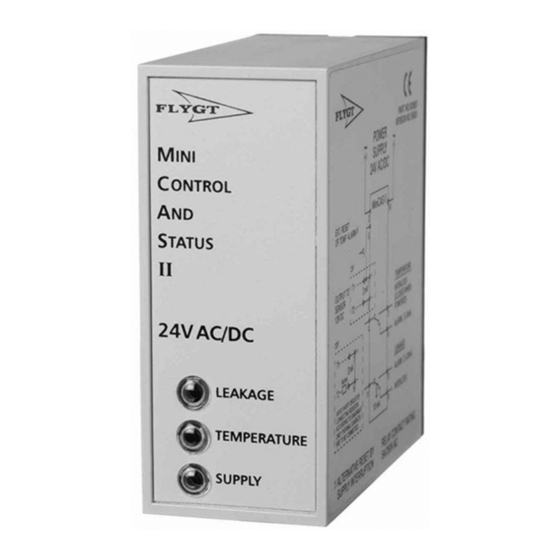
3 Product Description 3 Product Description 3.1 Product design The MiniCAS II overall purpose is to protect pumps and mixers. It is a monitoring relay for temperature and leakage sensors and is made to plug into a standard 11-pin socket. The relay monitors the following sensors: Type Description... -
Page 9: Installation
4 Installation 4 Installation Precautions Before starting work, make sure that the safety instructions in the chapter Introduction and Safety (page 2) have been read and understood. DANGER: Electrical Hazard Before starting work on the unit, make sure that the unit and the control panel are isolated from the power supply and cannot be energized. - Page 10 4 Installation – Overtemperature and leakage stop the pump ~(+) ~(+) ~(–) ~(–) 12 VDC – 10 s – Overtemperature stops the pump and leakage is only indicated ~(+) ~(+) ~(–) ~(–) 12 VDC – 10 s Position Description Alarm reset Sensor circuit Start and stop by a pump controller Power supply...
-
Page 11: Prevent Interference From A Variable Frequency Drive
4 Installation Position Description Auxiliary relay Pump contactor Pump main supply 2. Insert the MiniCAS II into the 11–pin socket. 4.3 Prevent interference from a variable frequency drive Interference from a variable frequency drive (VFD) can cause nuisance tripping of the CLS sensor. -
Page 12: Operation
5 Operation 5 Operation 5.1 The current levels for alarm lights When the current level is between 3–22 mA, it is only the SUPPLY LED that is light. Current level (mA) Type of alarm > 22 Leakage alarm < 3 Overtemperature alarm 5.2 LED indications Symptom... -
Page 13: Troubleshooting
6 Troubleshooting 6 Troubleshooting Precautions Before starting work, make sure that the safety instructions in the chapter Introduction and Safety (page 2) have been read and understood. DANGER: Electrical Hazard Troubleshooting a live control panel exposes personnel to hazardous voltages. Electrical troubleshooting must be done by a qualified electrician. -
Page 14: Test The Function Of The Relay
6 Troubleshooting 6.3 Test the function of the relay 1. Simulate a normal condition. a) Connect a 1 kilohm resistor in series with an ammeter to the sensor output. b) Connect terminal 6 and 7 to reset the relay. ~(–) ~(+) 12 VDC –... -
Page 15: Technical Reference
7 Technical Reference 7 Technical Reference 7.1 Dimensions Parameter Value mm (in) (W×H×D) 33×79×75 (1.29×3.11×2.95) 7.2 Environmental requirements Parameter Value Temperature -25˚ C – +60˚ C Operating humidity Relative humidity, non-condensing: 90% 7.3 Electrical data Version 24 VDC 24 VAC 120 VAC 230 VAC Supply voltage... -
Page 16: Circuit Functions
7 Technical Reference 7.5 Circuit functions ~(–) ~(+) 12 VDC – 10 s Relay connections Description 1–3 Normal temperature 1–4 Overtemperature 2–10 Power supply: 24 V AC/DC, 120 VAC, or 230 VAC 5–7 Sensor input from drive unit sensors: 12 V 6–7 Alarm reset 11–8... -
Page 17: Filter Connection Diagrams
7 Technical Reference Combination Configuration No fault Leakage (mA) (mA) 13.3 36–42 TC x 3 Thermal contacts 1.2 k − CLS must be connected with the correct polarity: brown = + and black = –. Thermal contacts TC x 3 1 kilohm resistor −... -
Page 18: Filter Kits
7 Technical Reference Filter part number Connection diagram 604 68 02 604 68 04 12 VDC – 661 60 00 661 60 01 TC x 3 WS009395A 7.8 Filter kits Drive unit Part.no 3102, 3127, 4430 6046800 3085, 4410 6046801 3140, 3152, 3170, 3201, 3300 6046802 3231, 3306, 3312, 3351, 3356, 3400, 3501, 3602, 3800, 7045, 7061, 7081, 7101, 7115,... - Page 20 For more information on how Xylem can help you, go to xyleminc.com Refer to www.xylemwatersolutions.com/contacts/ for contact details of your local sales and service representative.
Need help?
Do you have a question about the FLYGT MiniCAS II and is the answer not in the manual?
Questions and answers