
Related Manuals for Pottinger TOP 612


Summary of Contents for Pottinger TOP 612
- Page 1 Operator‘s manual + INSTRUCTIONS FOR PRODUCT DELIVERY . . . Page 3 "Translation of the original Operating Manual" 99 2719.GB.80Q.0 TOP 612 (Type SK 2719 : + . . 01001) Rotary swather...
- Page 2 Pöttinger - Trust creates Af nity - since 1871 "Quality pays for itself." Therefore we apply the highest quality standards to our products which are constantly monitored by our in-house quality management and our management board. Because the safety, perfect function, highest quality and absolute reliability of our machines in operation are the core competencies for which we stand.
- Page 3 INSTRUCTIONS FOR Dokument PRODUCT DELIVERY PÖTTINGER Landtechnik GmbH Industriegelände 1 A-4710 Grieskirchen Tel. 07248 / 600 -0 Telefax 07248 / 600-2511 According to the product liability please check the above mentioned items. Please check. Machine checked according to delivery note. All attached parts removed. All safety equipment, drive shaft and operating devices at hand.
-
Page 4: Table Of Contents
TABLE OF CONTENTS Table of contents SUPPLEMENT WARNING SIGNS Lubricants ..............31 CE symbol ..............5 Combination of tractor and mounted implement ..34 Meaning of warning signs .......... 5 OVERVIEW Overview ..............6 GENERAL SAFETY TIPS Travelling with implement in tow ........ 7 Coupling and uncoupling the implement .... -
Page 5: Warning Signs
WARNING SIGNS CE symbol The CE symbol, which is affixed by the manufacturer on the outside of the machine, indicates that this machine conforms to the engineering guideline regulations and the other relevant EU guidelines. EU Declaration of Conformity (see Attachment) By signing the EU Declaration of Conformity, the manufac- turer declares that the machine being brought into service complies with all relevant safety and health requirements. -
Page 6: Overview
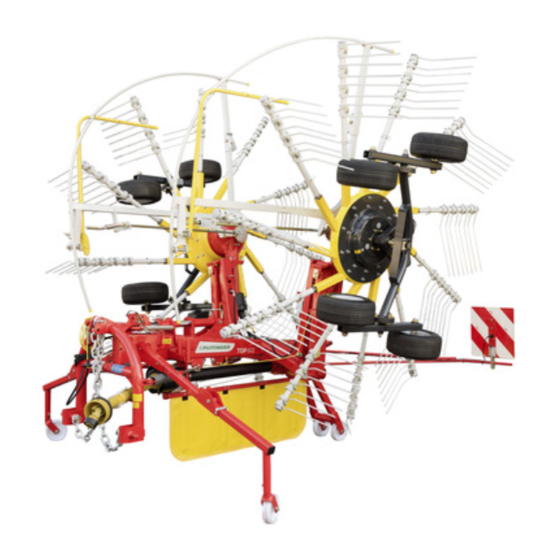
OVERVIEW Overview Designations: 1. Right rotor unit (in direction of travel) 2. Reflector boards 3. Rear support stand 4. Left rotor unit (in direction of travel) 5. Guard hoop 6. Crank handle for adjusting the rotor unit height. 7. Lower linkage attachment 8. -
Page 7: General Safety Tips
GENERAL SAFETY TIPS Travelling with implement in tow Before starting work Important! The attached implement influences the travelling a. Before commencing work, the operator must be aware characteristics of the towing vehicle. of all operating devices and functions.The learning General safety of these is too late after having already commenced hints for the use •... -
Page 8: Attaching
ATTACHING Road travel Support stands • Observe the statutory regulations for your country/state. Attaching See Supplement A1, Pt. 8a for safety information. - h.) • Attach machine to tractor's lifting gear. • Secure the hydraulic lower link (U) so that machine cannot swing out sideways. -
Page 9: Hydraulic Connection
ATTACHING Hydraulic connection Fit cardan shaft Connect hydraulic line to tractor - Switch off engine and remove ignition key. - Switch off pto before attaching - Before fitting the cardan shaft, clean and grease the machine's connection profiles and the pto. - Set tractor's control unit lever at "Neutral"... -
Page 10: Parking The Machine
ATTACHING Parking the machine Note: The parking height can be reduced by removing the The machine can be parked in either the working position tine arms. During transport, place the tine arms in the or transport position. tine arm rack provided (see diagram). Ensure stability when parked! - Fold front and rear support stands down and lock - Pull cardan shaft (GW) off and place on support. -
Page 11: From Transport To Working Position
WORKING POSITION From transport to working position 5. Swivel both rotor units down to the working position. • Set the single-acting control valve (ST) briefly at 075-09-05 "Raise", pulling the rope simultaneously. Doing this will release the locking hooks (11). Switching from working to transport position is only to be carried out on level, firm ground. -
Page 12: From Headland To Working Position
WORKING POSITION From headland to working position Check the working position - The centre gearbox (10) should be at the same height as both rotor gearboxes (17) (aligned with the cardan shafts) 1. Ensure that the swivel range is clear and that no-one is standing in the danger area. -
Page 13: Transport
TRANSPORT From working to transport position 5. Close stopcock (pos. A) 6. Lower deflection rail (10) 075-09-07 For safety reasons, switch off p.t.o. and wait for rotors to come to a standstill. Changing from working to transport position is only to be carried out on level, firm ground. -
Page 14: From Headland To Transport Position
Length reduced 3. Ensure that the swivel range is clear and that no-one is standing in the danger area. 4. Swivel both tine arms up to the transport position by TOP 612 3.40 2.90 2.70 6.08 setting the single-acting control unit at "Raise". -
Page 15: Reducing The Transport Height
TRANSPORT Reducing the transport height Carry out the following steps to reduce the transport height: In working position: - Remove the two outside tine arms from each rotor. Each tine arm is secured with a spring pin. - Store the tine arms in the rack provided. The tine rack is located on the front end of the machine, behind the headstock. -
Page 16: Operation
OPERATION General guidelines on working with the Should the tines pull the fodder out of the swath back onto the strip already raked (unclean work), reduce the pto speed. machine Where there are extremely uneven surfaces (like gullies, crossings, etc), raise the machine in order to prevent Safety advice: damage. -
Page 17: Set Cross Gradient
OPERATION 1. Set cross gradient 2. Adjusting rake height 1. Set rake height with the hand crank (1) - individually for To guarantee clean raking, the rotor chassis each rotor unit. Turn crank (1) anti-clockwise to increase should be tilted slightly toward the swath. As the distance of the tines to the ground. -
Page 18: Example - Left Rotor With Tandem Chassis
OPERATION Example - left rotor with tandem chassis: Requirement: - Level and solid ground - 1.5 bar pressure in all tyres Be advised! - The machine is attached to the tractor and in the working position Operating the machine without 482-15-15 inner feeler wheel is prohibited! -
Page 19: Cardan Shaft Speed
OPERATION Swath curtain Cardan shaft speed In order to achieve better work quality, it is recommended The maximum cardan shaft speed is: 540 rpm to use the swath curtain (70). The recommended cardan shaft speed is approx. 450 rpm Note: Reduce the pto speed if the crop being harvested is torn back from the swath by the tines and returned to the already... -
Page 20: Set The Cam Track
OPERATION Set the cam track When grass remains lying outside the swath, then the cam track can be adjusted. 1. Park machine on level ground and secure against rolling. (use wheel chocks) 2. Remove the three plastic covers (1) from the openings on the underside of the rotor unit to gain access to the screws (2) on the cam track. -
Page 21: Maintenance
MAINTENANCE Maintenance and Servicing Winter storage - Thoroughly clean the machine beforehand. For safety information see - Put up weather protection. Supplement A "Replacement Parts" - Change or top up gear oil • Turn motor off before any adjustment, maintenance or - Protect exposed parts from rust. -
Page 22: Rotor Unit
MAINTENANCE - Insert new tine arm. Turn the rotor unit so that the Changing the bearing bush of the tine arms new tine arm can be inserted between the in and • The distance (A) in normal operation must be about 1 out controls (see below). - Page 23 MAINTENANCE Lubricating the transmission: Note: Fill with liquid grease: if required Only enter the danger area when there is 1. Open oil filling screw (1). The crown wheel toothing no other option. Make sure beforehand is easily visible when the filling screw is open. that 2.
-
Page 24: Lubrication Chart
LUBRICATION CHART Lubrication chart 1x annually every 20 operating hours every 50 operating hours - 24 - 1500_GB-LUBRICATION CHART_2719... -
Page 25: Technical Data
TECHNICAL DATA Technical data TOP 612 (Type SK 2719) Number of rotors ................2 Number of tine arms per rotor ............11 Working width (m) ..............5.90 Machine width in working position (m) ........6.08 Transport width folded up (m) ........... 2.70 Length (m) ................. -
Page 26: Type Plate Position
Please enter the number on the Operating Instructions' title page immediately upon taking delivery of vehicle/machine. Using the rotary swath as designated The rotary swather "TOP 612" is designed solely for customary use in agricultural work. • To rake green fodder, coarse fodder, silage fodder and straw. - Page 27 SUPPLEMENT GB-Anhang Titelblatt _BA-Allgemein...
- Page 28 The original cannot be copied ... Things will run better with genuine Pöttinger parts • Quality and precise fitting The decision must be made, ”original” or ”imitation”? The decision is often governed by price and a ”cheap buy” can sometimes be very expensive. - Operating safety.
- Page 29 PTO SHAFT Supplement - B Matching driveshaft to tractor Instructions for working To determine the actual length required, hold the two halves The permissible pto speed may not be exceeded when Be advised! of the driveshaft side by side. using the implement. - The hitched implement may continue to run after the Only use the pto is switched off.
- Page 30 PTO SHAFT Supplement - B Information on function when using a cam shifting clutch. This overload clutch switches the torque transmitted to zero if overloaded. To revert to normal operation, stop the p.t.o. drive briefly. The clutch reengages at a speed below 200 rpm. Be advised! Re-engaging is also possible by decreasing the p.t.o.
-
Page 31: Lubricants
- 31 - 1400_EN-BETRIEBSSTOFFE... - Page 32 - 32 - 1400_EN-BETRIEBSSTOFFE...
- Page 33 - 33 - 1400_EN-BETRIEBSSTOFFE...
-
Page 34: Combination Of Tractor And Mounted Implement
IMPORTANT! ADDITIONAL INFORMATION Combination of tractor and mounted implement The mounting of implements on the front or rear three point linkage shall not result in exceeding the maximum permissible weight, the permissible axle loads and the tyre load carrying capacities ot the tractor. The front axle of the tractor must always to be loaded with at least 20 % of the unladen weight of the tractor. - Page 35 IMPORTANT! ADDITIONAL INFORMATION 3. CALCULATION OF THE REAL FRONT AXLE LOAD T V tat (If with the front mounted implement (G ) the required minimum front ballasting (G ) cannot be reached, the weight of the front mounted V min implement has to be increased to the weight of the minimum ballasting at the front!) Record the calculated real front axle load and the permissible front axle load of the tractor into the table.
- Page 36 Name and address of the manufacturer: PÖTTINGER Landtechnik GmbH Industriegelände 1 AT - 4710 Grieskirchen Machine (interchangeable equipment): rotary rake TOP 612 Type 2719 Serial no. The manufacturer declares that the machines adhere to all relevant provisions in the following EU directive:...
- Page 37 Im Zuge der technischen Weiterentwicklung La société PÖTTINGER Landtechnik GmbH Following the policy of the PÖTTINGER arbeitet die PÖTTINGER Landtechnik améliore constamment ses produits grâce Landtechnik GmbH to improve their products GmbH ständig an der Verbesserung ihrer au progrès technique. as technical developments continue, Produkte.
- Page 38 PÖTTINGER Landtechnik GmbH A-4710 Grieskirchen Telefon: +43 7248 600-0 Telefax: +43 7248 600-2513 e-Mail: info@poettinger.at Internet: http://www.poettinger.at PÖTTINGER Deutschland GmbH Verkaufs- und Servicecenter Recke Steinbecker Strasse 15 D-49509 Recke Telefon: +49 5453 9114-0 Telefax: +49 5453 9114-14 e-Mail: recke@poettinger.at PÖTTINGER Deutschland GmbH Servicecenter Landsberg Spöttinger-Straße 24 Postfach 1561...
Need help?
Do you have a question about the TOP 612 and is the answer not in the manual?
Questions and answers