Table of Contents

Subscribe to Our Youtube Channel
Related Manuals for Pottinger TOP 722


Summary of Contents for Pottinger TOP 722
- Page 1 All manuals and user guides at all-guides.com Operator‘s manual 99+2862.EN.80U.0 Translation of the original Operating Manual Double rotary swather TOP 722 (Type SK 2862 : + . . 00001) TOP 812 (Type SK 2863 : + . . 00001)
- Page 2 All manuals and user guides at all-guides.com Pöttinger - Trust creates Affinity - since 1871 "Quality pays for itself." Therefore we apply the highest quality standards to our products which are constantly monitored by our in-house quality management and our management board. Because the safety, perfect function, highest quality and absolute reliability of our machines in operation are the core competencies for which we stand.
- Page 3 All manuals and user guides at all-guides.com INSTRUCTIONS FOR PRODUCT HANDOVER PÖTTINGER Landtechnik GmbH Industriegelände 1 4710 Grieskirchen, Austria Tel. 07248 / 600 -0 Telefax 07248 / 600-2511 According to the product liability please check the above mentioned items. Please place a cross where appropriate. ...
-
Page 4: Table Of Contents
Parking the machine ..........16 TOP 722 hydraulic plan ........... 44 Adjusting the rotor stabilisation .........17 TOP 722 hydraulic plan - single rotor operation ..45 Safety advice ............18 TOP 722 hydraulic plan - single rotor operation and TRANSPORT hydraulic release ............ -
Page 5: Ce Sign
All manuals and user guides at all-guides.com Table of conTenTs CE sign The CE sign, which is affixed by the manufacturer, indicates outwardly that this machine conforms to the engineering guideline regulations and the other relevant EU guidelines. EU Declaration of Conformity By signing the EU Declaration of Conformity, the manufacturer declares that the machine being brought into service complies with all relevant safety and health requirements. -
Page 6: Symbols Used
All manuals and user guides at all-guides.com symbols used CE mark The CE mark, which is affixed by the manufacturer, indicates outwardly that this machine conforms to the engineering guideline regulations and the other relevant EU guidelines. EU Declaration of Conformity (see Attachment) By signing the EU Declaration of Conformity, the manufacturer declares that the machine that is brought into service complies with all relevant fundamental safety and health requirements. -
Page 7: Warning Signs
All manuals and user guides at all-guides.com Warning signs 060-19-001 060-19-002 Never reach into the crushing danger area as long as parts can move there. (2x) 495.171 Never reach into the crushing danger area as long as parts can move there. - Page 8 All manuals and user guides at all-guides.com Warning signs Preferred hydraulic pressure and cardan shaft speed. (1x) 495.310 Zuschnittlinie Shut engine off and remove key before carrying out maintenance or repair work. (1x) 495.165 Secure your right to product warranty by signing the delivery declaration. 116 mm (1x) 495.713...
- Page 9 All manuals and user guides at all-guides.com Warning signs Tyre pressure (2x) 495.668 Do not enter the rotor arms swivel range (2x) 495.166 495.166 bsb 449 567 A grease nipple position (12x) 494.646 Cut cardan shaft to length (1x) 495.851 1800_GB-Warning signs_2858 - 9 -...
-
Page 10: General Safety Tips
All manuals and user guides at all-guides.com General safety tips Travelling with implement in tow Before starting work The attached implement influences the travelling a. Before commencing work, the operator must be aware characteristics of the towing vehicle. of all operating devices and functions.The learning of these is too late after having already commenced •... -
Page 11: Description Of Services
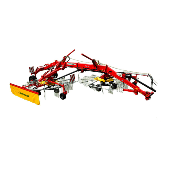
All manuals and user guides at all-guides.com descriPTion of serVices Overview Designations: (1) Chassis (2) Rotor unit right rear (3) Swath apron (4) Rotor unit left front (5) Lower link attachment with support foot (6) Inside feeler wheel (7) Outside feeler wheel (optional) (8) Spare wheel suspension for rotor chassis - 11 - 1300_GB-ÜBERSICHT_2862... -
Page 12: Tractor
- The limiting chain or lower link stabilisers (5) are to - Tractor output: TOP 722: from 44 kW / 60 be set so that the attached machine CANNOT move sideways. (Safety measure for transportation) -
Page 13: Necessary Hydraulic Connections
Standard Raising and lowering the rotor units Standard Moving the rotor units apart (only TOP 812) Optional Dual swath device (only TOP 722) *) Floating (Neutral) position required Power connections required Design Consumer Volt Power connection Standard Lighting... -
Page 14: Attaching The Machine
All manuals and user guides at all-guides.com aTTaching The machine Attach the machine - Connect hydraulic hoses Safety - Lay rope into tractor cabin Attach the rake: advice: - Attach headstock on the lower linkage of the tractor see Supplement A1 Fit cardan shaft Point 8a. -
Page 15: Adjusting The Linkage At The Transport Securing Device
All manuals and user guides at all-guides.com AttAching the mAchine 1. Breakaway chain for lower link hitch: 4. Screw upper nut (2) downwards until the rotor arm lifts when you set the control device to "Lift". 5. Lock position with bottom nut (1) 094-18-402 2. -
Page 16: Parking The Machine
All manuals and user guides at all-guides.com AttAching the mAchine Parking the machine The machine can be parked in the working or transport positions. Attention! - Park the machine stably! - Secure the machine against rolling with wheel chocks. - Control unit in floating position - Release spring-loaded bolts (B) - Swivel support stand (5a) up and allow to engage Attention! -
Page 17: Adjusting The Rotor Stabilisation
All manuals and user guides at all-guides.com AttAching the mAchine Adjusting the rotor stabilisation Attention! Risk of injury due to crushing Carry out adjustment only when the tractor engine is switched off. Remove ignition key and keep safe. Adjust gyro stabilization: After adjustment, the gyro units should hang horizontally or slightly outwards. -
Page 18: Safety Advice
All manuals and user guides at all-guides.com TransporT Safety advice DANgER life-threatening danger through machine tipping over. • Carry out the change from working position to transport position, and vice versa, only on level, firm ground! DANgER life-threatening danger exists through moving parts when changing from transport to working position. -
Page 19: Conversion From Working Position To Transport Position
- Check the correct locking of the transport securing transport position device (7). 075-09-07 1. Raising the rotors at TOP 722 - Lift the rotors into field transport position using the dual-action control unit (1). - Completely retract the extendable rotor arms using... -
Page 20: Driving On Public Roads
The following dimensions will not be exceeded if the trans- port position is established correctly: Type H e i g h t Width (m) l e n g t h TOP 722 3.99 2.54 8.90 TOP 722 with 3.99 2.80 8.90 wide driving frame TOP 812 3.99 2.80 9.70... -
Page 21: Frame - Chassis
All manuals and user guides at all-guides.com TransporT Frame - chassis The frame chassis is steerable. The swivelling headstock transfers the steering movement to the frame chassis using a steering rod. In the optimum basic setting, the frame chassis is trailed flush to the tractor when driving straight ahead. -
Page 22: Reducing The Transport Height
All manuals and user guides at all-guides.com TransporT Reducing the transport height Operation of the tine holder The following steps are to be performed to reduce (by 1. Pull the handle (3) of the lock in driving direction approx. 450mm) the implement height in transport position: backwards (a) and then towards the body (b) to open the locking device. -
Page 23: Operation
All manuals and user guides at all-guides.com oPeraTion general guidelines on working with the Conversion from transport to working machine position 075-09-05 DANgER life-threatening danger exists through rotating rotors and folding arms • Turn the rake off before leaving the cabin. DANgER •... -
Page 24: Settings On Rotor Chassis
All manuals and user guides at all-guides.com OperatiOn 1. Fully extend retracted rotor arms using control unit 2 (only TOP 812) 2. Briefly raise the rotors to release the transport Secure crank handle in holding bracket after setting safeguard (10) using the dual-acting control unit 1. has taken place. -
Page 25: 2B. Set Raking Height (Hydraulic)
All manuals and user guides at all-guides.com OperatiOn - Remove M8 screw (1) With that the connection between the outer and inner feeler wheel is broken. - Set outside feeler wheel using crank handle (2). - Reinstate connection between outer and inner feeler wheel using M8 screw (1). -
Page 26: Align Indicators To One Another
All manuals and user guides at all-guides.com OperatiOn Adjust feeler wheels Comfort control for raking height and single rotor operation: 1. Adjust the inner feeler wheel height using the tensioning screws (TS). The rotor should be inclined slightly towards the swath to ensure clean raking. -
Page 27: Cardan Shaft Speed
The extending swath apron may cause bodily injury. Cardan shaft speed The maximum cardan shaft speed is: 540 rpm The recommended cardan shaft speed is: approx. 450 rpm for TOP 722 approx. 400 rpm for TOP 812 - 27 - 2000_DE_Operation 2862... -
Page 28: Dual-Swath Function (Optional Equipment For Top 722)
Risk of material damage due to collision with Dual-swath function (Optional electric cables, bridges and other obstacles in equipment for TOP 722) the environment if the maximum machine height is exceeded. Switching from a single swath to two swaths takes place •... -
Page 29: Swivelling From Working To Field Transport Position
All manuals and user guides at all-guides.com OperatiOn The dual-swath function is only available in combination DANgER with the 2.80 m wide chassis. life-threatening danger exists through moving parts when changing from transport to working position. Possible working widths: 075-09-05 Single swath operation (A1): 6.8m •... -
Page 30: Single Rotor Operation (Variant)
All manuals and user guides at all-guides.com OperatiOn The time to activate the commands can be adjusted Raising the other rotor individually: To change the time, loosen the bolts of the 1. Select the lowered rotor on the single-rotor control unit appropriate disc and change the position of the disc relative B. -
Page 31: Setting The Cam Track
All manuals and user guides at all-guides.com OperatiOn Setting the cam track The cam track can be adjusted if grass is left lying outside the swath. 1. Park the machine on an even surface and secure it against rolling off. (Use wheel chocks) 2. -
Page 32: Working On Inclines
All manuals and user guides at all-guides.com WorkinG on inclines Take care when turning on inclines! • when cornering with the rotor units in the transport position. DANgER life-threatening danger through the tractor/trailer tipping on an incline, especially in transport position and when cornering. -
Page 33: General Maintenance
All manuals and user guides at all-guides.com general mainTenance Safety advice Spare parts a. Genuine parts and accessories are specially designed for the machines. DANgER b. We expressly draw your attention to the fact that genuine life-threatening danger exists through moving or parts and accessories not supplied by us, have not been rotating parts tested and approved by us. -
Page 34: Articulated Shafts
All manuals and user guides at all-guides.com General maintenance Articulated shafts - See information in the supplement Please observe the following for maintenance! The directions in these Operating Instructions apply. If no particular instructions are available here, then the information in the instructions supplied by the respective cardan shaft manufacturer apply. -
Page 35: General Instructions Regarding Maintenance Work
All manuals and user guides at all-guides.com MAINTENANCE general instructions regarding Transmission (1.2) maintenance work DANgER life-threatening danger exists if another person starts up the tractor and drives away or actuates the control lever of the hydraulic system while you are engaged in maintenance. -
Page 36: Tyres
All manuals and user guides at all-guides.com MAINTENANCE 3. Lock the bar with the nuts (1, 2). - Remove cover Tyres - Pull tine arm out. Turn the rotor unit so that the old tine arm can be pulled out between the intake and output (see below). -
Page 37: Spring Tines
All manuals and user guides at all-guides.com MAINTENANCE Spring tines Check the fixing bolts (S) of the spring tines after the first 10 hours of operation and re-tighten if necessary (tightening torque: 100 Nm). The outer tines are shorter and thicker. If the implement has a tine loss securing device, the two outer tines are connected;... -
Page 38: Lubrication Diagram
All manuals and user guides at all-guides.com MAINTENANCE lubrication diagram See "Operating Materials" supplement for more detailed information on the lubricants to be used. - 38 - 2000-DE Maintenance_2862... -
Page 39: Rotor Unit
- Pump grease gun 3-4 times during a full rotation - Make 3-4 full rotations 2. Implementation: 1. Bring the machine to transport position TOP 722 2. Open the drain plug (2) TOP 812 Drive of the rotary unit Refill grease 3. -
Page 40: Disposal Of Old Equipment
All manuals and user guides at all-guides.com MAINTENANCE Disposal of old equipment Take service-life expired equipment to a legally regulated waste material recycling centre. Raising the machine The position (1) at which the jack may be used is indicated by stickers on both stub axles, left and right. - 40 - 2000-DE Maintenance_2862... -
Page 41: Air Brake System
All manuals and user guides at all-guides.com air brake sysTem Coupling the air brake hoses Safety advice When coupling the air brake hoses pay attention WARNINg to the following: - that the sealing rings of the coupling heads are clean Risk of injury resulting in death or other serious injury from incorrectly installed brakes. -
Page 42: Line Filter Cleaning
The brakes are factory-set to the tyres included in the delivery. In case you change to another tyre, this table will help you to find the right settings for the cylinder position and the brake linkage. TOP 722 - Air brake Tyres Cylinder length of the... -
Page 43: Hydraulic Brake System
In case you change to another tyre, this table will help you to find the right settings for the cylinder position and the brake linkage. Coupling the brake hose TOP 722 - Hydraulic brake When coupling the brake hose, make sure: Tyres Cylinder... -
Page 44: Hydraulic Plan
All manuals and user guides at all-guides.com hydraulic Plan TOP 722 hydraulic plan 442.395 442.395 445.617 445.089 445.089 445.617 445.113 key: T-adapter 1 Disc 1 Angle 2 Disc 2 Hose/pipe 3. Tractor control unit, double-acting Scheibe 1 0° Straight hose end 4 Front headland 90°... -
Page 45: Top 722 Hydraulic Plan - Single Rotor Operation
All manuals and user guides at all-guides.com Hydraulic plan TOP 722 hydraulic plan - single rotor operation 442.395 442.395 445.295 445.617 445.089 445.089 445.617 445.526 445.113 Explanation: T-adapter 1 Disc 1 Angle Scheibe 1 2 Disc 2 Hose/pipe Scheibe 2 3 Tractor control unit, dual-acting 0°... -
Page 46: Top 722 Hydraulic Plan - Single Rotor Operation And Hydraulic Release
All manuals and user guides at all-guides.com Hydraulic plan TOP 722 hydraulic plan - single rotor operation and hydraulic release 442.395 442.395 445.295 445.617 445.089 445.089 445.602 445.617 445.526 2862.48.020.0 2862.48.020.0 40 bar 445.626 445.540 445.540 key: T-adapter 1 Disc 1... -
Page 47: Top 722 Hydraulic Plan - Single Rotor Operation, Hydraulic Release And Raking Height
All manuals and user guides at all-guides.com Hydraulic plan TOP 722 hydraulic plan - single rotor operation, hydraulic release and raking height 141.22.123.0 442.395 442.395 0,8mm 445.295 445.411 445.411 445.617 141.22.123.0 445.089 445.089 0,8mm 445.602 445.617 445.526 445.526 445.526 2862.48.020.0 2862.48.020.0... -
Page 48: Top 722 Hydraulic Plan - Dual Swath Operation
All manuals and user guides at all-guides.com Hydraulic plan TOP 722 hydraulic plan - dual swath operation 442.395 442.395 442.512 442.512 445.617 445.089 445.089 445.617 445.113 Scheibe 1 Scheibe 2 key: T-adapter Traktor Steuergerät, doppelt wirkend 1 Disc 1 Vorgewende vorne... -
Page 49: Top 722 Hydraulic Plan - Flow Divider (Optional)
All manuals and user guides at all-guides.com Hydraulic plan TOP 722 hydraulic plan - flow divider (optional) 442.395 442.395 445.617 445.089 445.089 445.602 445.617 445.113 key: T-adapter 1 Disc 1 Angle 2 Disc 2 Hose/pipe Scheibe 1 3 Tractor control unit, dual-acting 0°... -
Page 50: Hydraulic Plan For Top 812
All manuals and user guides at all-guides.com Hydraulic plan Hydraulic plan for TOP 812 442.395 442.395 442.517 442.517 445.617 445.089 445.089 445.617 445.552 445.113 key: T-adapter 1 Disc 1 Scheibe 1 Angle 2 Disc 2 Scheibe 2 Hose/pipe 3 Tractor control unit, dual-acting Traktor Steuergerät, doppelt wirkend 0°... -
Page 51: Top 812 Hydraulic Plan - Single Rotor Operation
All manuals and user guides at all-guides.com Hydraulic plan TOP 812 hydraulic plan - single rotor operation 442.395 442.395 442.517 442.517 445.295 445.617 445.089 445.089 445.617 445.552 445.526 445.113 Scheibe 1 key: Scheibe 2 T-adapter Traktor Steuergerät, doppelt wirkend 1 Disc 1 Angle Vorgewende vorne 2 Disc 2... -
Page 52: Top 812 Hydraulic Plan - Flow Divider
All manuals and user guides at all-guides.com Hydraulic plan TOP 812 hydraulic plan - flow divider 442.395 442.395 442.517 442.517 445.617 445.089 445.089 445.602 445.617 445.552 445.113 Scheibe 1 key: T-adapter Scheibe 2 1 Disc 1 Angle Traktor Steuergerät, doppelt wirkend 2 Disc 2 Hose/pipe Vorgewende vorne... -
Page 53: Technical Data
All manuals and user guides at all-guides.com tecHnical Data Technical data Description TOP 722 (Type 2862) TOP 812 (Type 2863) Number of rotors Number of tine arms per rotor Rotor diameter 3.3 m 3.7 m Working width 6.8 - 7.6 m 7.6 m... -
Page 54: Optional Equipment
• Dual-swath function (only TOP 722) • Wide chassis (=2.8m) (only TOP 722) • Narrow chassis (=2.55m) (only TOP 722) • hydraulic single-rotor lateral shift (only TOP 722) • hydraulic rake height adjustment (only TOP 722) • hydraulic locking mechanism (only TOP 722) Designated use of the swath rotor The swath rotor is designated for customary use in agricultural work. -
Page 55: Supplement
All manuals and user guides at all-guides.com supplement GB-Anhang Titelblatt _BA-Allgemein... - Page 56 All manuals and user guides at all-guides.com The original cannot be copied ... Things will run better with genuine Pöttinger parts • Quality and precise fitting The decision must be made, ”original” or ”imitation”? The decision is often governed by price and a ”cheap buy” can sometimes be very expensive. - Operating safety.
- Page 57 All manuals and user guides at all-guides.com Supplement - A Safety advice v. Secure the machine before leaving the tractor! w. Lower attached machinery completely! Turn motor off and remove ignition key! This operating manual contains this symbol at all points relating to the safety of persons.
- Page 58 All manuals and user guides at all-guides.com Supplement - A the machine’s danger area! j. Never turn p.t.o. on when motor is turned off! 7. Maintenance k. When working with the p.t.o., ensure nobody is in the a. In principle, any overhaul, maintenance and cleaning danger areas where the rotating p.t.o.
- Page 59 All manuals and user guides at all-guides.com Cardan shaft Supplement - B Adapting cardan shaft to tractor Ensure sufficient swivel space for the cardan shaft! - Trim the safety chain so that it cannot wind around the cardan shaft. NOTE material damage - due to inferior spare parts •...
- Page 60 All manuals and user guides at all-guides.com Cardan shaft Supplement - B Important for driveshafts with friction - Lubricate with a brand-name grease before starting work and every 8 hours worked. clutch - Before any extended period of non-use, clean and lubricate driveshaft.
-
Page 61: Lubricants
All manuals and user guides at all-guides.com - 61 - 1400_EN-BETRIEBSSTOFFE... - Page 62 All manuals and user guides at all-guides.com - 62 - 1400_EN-BETRIEBSSTOFFE...
- Page 63 All manuals and user guides at all-guides.com - 63 - 1400_EN-BETRIEBSSTOFFE...
-
Page 64: Combination Of Tractor And Mounted Implement
All manuals and user guides at all-guides.com Important! addItIonal InformatIon Combination of tractor and mounted implement The mounting of implements on the front or rear three point linkage shall not result in exceeding the maximum permissible weight, the permissible axle loads and the tyre load carrying capacities ot the tractor. The front axle of the tractor must always to be loaded with at least 20 % of the unladen weight of the tractor. - Page 65 All manuals and user guides at all-guides.com Important! addItIonal InformatIon 3. CALCULATION OF THE REAL FRONT AXLE LOAD T V tat (If with the front mounted implement (G ) the required minimum front ballasting (G ) cannot be reached, the weight of the front mounted V min implement has to be increased to the weight of the minimum ballasting at the front!) Record the calculated real front axle load and the permissible front axle load of the tractor into the table.
- Page 66 Name and address of the manufacturer: PÖTTINGER Landtechnik GmbH Industriegelände 1 AT - 4710 Grieskirchen Machine (interchangeable equipment): rotary rake Type TOP 722 TOP 812 Serial no. 2862 2863 The manufacturer declares that the machines adhere to all relevant provisions in the following EU directive:...
- Page 67 All manuals and user guides at all-guides.com Im Zuge der technischen Weiterentwicklung Following the policy of the PÖTTINGER La empresa PÖTTINGER Landtechnik arbeitet die PÖTTINGER Landtechnik Landtechnik GmbH to improve their products GmbH se esfuerza contínuamente en GmbH ständig an der Verbesserung ihrer as technical developments continue, la mejora constante de sus productos, Produkte.
- Page 68 All manuals and user guides at all-guides.com PÖTTINgER landtechnik gmbH Industriegelände 1 A-4710 Grieskirchen Telefon: +43 7248 600-0 Telefax: +43 7248 600-2513 e-Mail: info@poettinger.at Internet: http://www.poettinger.at PÖTTINgER Deutschland gmbH Servicecenter Deutschland Nord Steinbecker Str. 15 D-49509 Recke Telefon: +49 5453 911 4-0 e-Mail: recke@poettinger.at PÖTTINgER Deutschland gmbH Servicecenter Deutschland Süd...
Need help?
Do you have a question about the TOP 722 and is the answer not in the manual?
Questions and answers