
Related Manuals for Motorola DDS/MR64


Summary of Contents for Motorola DDS/MR64
- Page 1 DDS/MR64 Installation and Operation Motorola Doc No. 6 456 5246 02 014 5000 Bradford Drive October 1994 Huntsville, AL 35805-1993 © 1994 Motorola...
- Page 2 Updates to the products and the manual are obtainable at participating Motorola dealers and distributors, or directly from Motorola on the same terms and conditions as those offered by Motorola to its registered customers as verified by the completion and return of the registra-...
- Page 3 You will be notified of changes in advance to give you ample time to maintain uninter- rupted telephone service. If you experience trouble with this telephone equipment, please contact Motorola 5000 Bradford Drive Huntsville, AL 35805-1993 Telephone: (205) 430-8000 for information on obtaining service or repairs.
- Page 5 PREFACE This manual is written for users of the DDS/MR64. Please read the appropriate chapters before you change any option on the printed circuit board, change dip switches, or operate the unit. The manual includes the following: Chapter 1 Introduction - Contains introductory information and equipment description;...
- Page 6 STATEMENT OF APPLICATION This manual supports both the standalone and shelf mount units. Opera- tion and function of either unit is identical. Where necessary, this manual provides detailed information in support of the standalone unit. Detailed information in support of the shelf mount unit can be found in the shelf installation and operation manual.
-
Page 7: Table Of Contents
DDS/MR64 Chapter 1 Introduction GENERAL ................PHYSICAL DESCRIPTION ............ FUNCTIONAL ................. FEATURES ................COMPATIBILITY ..............COMPLIANCE ................ Chapter 2 Installation RECEIPT INSPECTION ............SITE PREPARATION .............. HARD OPTIONS ..............INSTALLATION ..............Chapter 3 Operation GENERAL ................DATA TERMINAL EQUIPMENT (DTE) ....... - Page 8 Front Panel Initiated Tests ............Configuration Option Menu ........... STRAP/SWITCH CONFIGURATION ........4-11 Cover Removal ............... 4-12 Replacing the Cover ............... 4-12 Front Panel Option ..............4-14 Chassis Signal Ground ............4-14 DTE Interface ................. 4-15 Chapter 5 Diagnostics TEST FEATURES ..............viii DDS/MR64...
- Page 9 INSTALLATION ..............TIMING ..................OPTIONS .................. TESTS ..................Chapter 8 Rate Adapter Option GENERAL ................FRONT PANEL DISPLAY ............Operating Distance ..............RATE ADAPTER CONFIGURATION OPTIONS ....Timing ..................Rate ..................Chapter 9 Maintenance GENERAL ................FUSE ..................MAINTENANCE ..............DDS/MR64...
- Page 10 Table of Contents Appendix A Specifications DDS/MR64...
-
Page 11: Chapter 1 Introduction
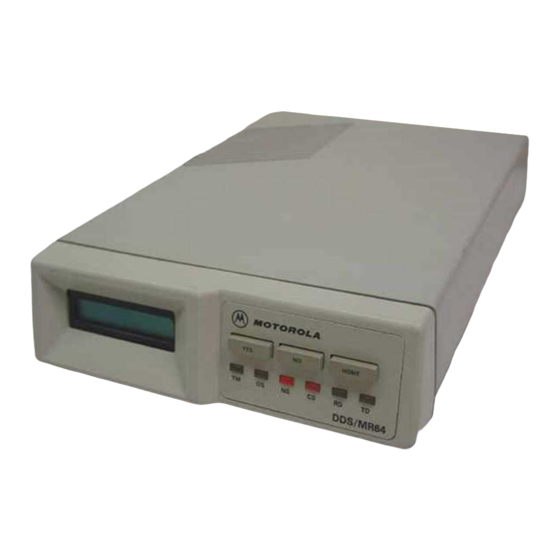
Chapter 1 Introduction GENERAL The Motorola DDS/MR64 is a digital data unit that allows you to connect your computer or other DTE unit directly to the digital network without any other network access device. The unit pumps data at up to 64 kbps in point-to-point or multipoint applications. - Page 12 Introduction HOME DDS/MR64 Figure 1-1 Front Panel 1/4 AMP S.B. POWER 115 VAC 60 HZ 1/4 AMP Figure 1-2 Rear Panel DDS/MR64...
-
Page 13: Features
• Synchronous or asynchronous 1200 bps over 2400 bps lines. COMPATIBILITY Compatible with the Motorola DDS/MR series of products with the exception of running the DDS/MR1 or the DDS/MR56 at 64 kbps. Compatible with Bell 500 Series DSU and CSU equipment. - Page 14 Introduction DDS/MR64...
-
Page 15: Chapter 2 Installation
Inspect the equipment carefully for damage that may have occurred in shipment. If there is damage or material shortage, contact the ship- ping agent and Motorola for advice and assistance. You should keep the shipping container and packing material for future shipment. - Page 16 Installation The DDS/MR64 will now perform all functions as determined by option configuration (Chapter 4). EIA-232 25-pin connector to DTE 8-pin 1/4 AMP S.B. POWER 115 VAC 60 HZ Power 1/4 AMP cord RJ48 jack cable Figure 2-1 Connection Using the RJ48 Jack...
- Page 17 42A block 1/4 AMP S.B. POWER 115 VAC 60 HZ 1/4 AMP Power cord cable Terminal block Orange modem TX Pair Blue Green central Black Brown office RX Pair Yellow Gray Screw terminal Figure 2-2 Connection Using the 42A Block DDS/MR64...
- Page 18 Installation DDS/MR64...
-
Page 19: General
DDS/MR64 will perform all configured functions. DATA TERMINAL EQUIPMENT (DTE) The DTE interface to the DDS/MR64 is through a 25-pin, D-type connector. The sense levels and impedances conform to either EIA-232 or CCITT V.35 INTERFACE depending on the option switch selected. - Page 20 Data Set Ready (DSR) Received Line Signal Detector (RLSD) Test mode K and NN † No signal † Rx data A Rx data B Rx clock A Rx clock B Tx clock A Tx clock B Tx data A DDS/MR64...
- Page 21 † Selected by DTE interface dip switches Request to Send RTS This signal goes on when the DTE wants to send data. When RTS is on, the DDS/MR64 is in transmit mode and responds by turning on Clear to Send (CTS). Clear to Send CTS This signal goes on when the DDS/MR64 is ready to transmit data and is in response to RTS going on.
- Page 22 25% of the nominal bit time. Transmit Data TD This signal goes on when the DTE transmits data to the DDS/MR64. External Clock This signal goes on when the DTE sends transmit timing information to the DDS/MR64.
-
Page 23: Receive Clock
Receive Data RD This signal goes on when the DDS/MR64 provides the DTE with data received from the communications line. Transitions of this lead occur within ± 25% of the nominal bit time. This signal is held in a mark state when RLSD is off. -
Page 24: Dte Initiated Test Signals
DDS communication line. Remote Terminal Loopback When the DTE turns RT on, the DDS/MR64 loops data to and from the DDS line through the DTE interface. A bilateral loopback also provides a loopback path for connecting the DTE transmit and receive data. -
Page 25: Dds System Interface
DDS line. SEALING CURRENT When the DDS/MR64 is used as a Limited Distance Modem, the DDS/ MR64 has the ability to source sealing current. A dip switch (Figure 3- 1) on the stand alone unit PC board or the auxiliary jack along with the dip switch on the shelf mount unit provides this service. -
Page 26: Front Panel Indicators
FRONT PANEL INDICATORS Pushbuttons Configuration control is through the three pushbuttons on the front panel. The pushbuttons allow the user to configure the DDS/MR64 or select a test mode. The three pushbuttons are: Selects the displayed menu option Advances the displayed menu option... -
Page 27: Lcd
• TM ON when the DDS/MR64 is in a Test Mode. Blinks at one half second rate when the DDS/MR64 is placed in RT loopback by the Telco. Blinks at one second rate when placed in RL by the remote DSU. - Page 28 Operation 3-10 DDS/MR64...
-
Page 29: Chapter 4 Configuration
PC board configure signal ground and the DTE inter- face. CONFIGURATION ON POWER-UP After installation, turn the power on. The DDS/MR64 will perform a self test. If the test fails, the LCD displays ERROR. If an error occurs ensure it is consistent and then refer to Maintenance. -
Page 30: Configuration Option Descriptions
The rate option is selectable to 2.4, 4.8, 9.6, 19.2, 56 kbps, or 64 kbps clear channel. Synchronous/AsynchronousSYNC/ASYNC The sync/async option is used to configure the DDS/MR64 to operate either synchronously or asynchronously. Bits Per WordBITS/WORD The bits/word option is used to select the asynchronous word size. The word size is computed by adding the number of data bits, the number of stop bits, the number of parity bits (0 to 1), and one start bit. -
Page 31: Rts Control
• 35 sec AS - 35 second anti-streaming terminal disconnect. In this mode, if RTS is on from the DTE for 35 continuous seconds, the DDS/MR64 turns CTS OFF. • SIM SW CR - Simulated switched carrier. Provides a permanent RTS to the DSU/CSU. -
Page 32: System Status
When on, RLSD must be on for CTS to be on. This means that CTS will turn off while receiving Idle or Out-of-Service codes. When this option is off, CTS does not depend on the state of the DDS/MR64 receiver. This option can be used when the remote DDS/MR64 maintains a permanent RTS to verify a complete link before sending data. -
Page 33: Option Selection
OPTION SELECTION Front Panel Option Selection The DDS/MR64 operates in either DATA or SET mode. DATA mode is for normal operation. SET mode allows the user to initiate tests or select soft strap configuration options. DATA mode displays one of the... -
Page 34: Front Panel Initiated Tests
Front Panel Initiated Tests “SELECT TEST?” is the first question of SET mode. If NO is pressed the DDS/MR64 proceeds to the configuration options menu. If YES is pressed the DDS/MR64 enters the test menu. Test choices are displayed with a question mark. To enter a desired test press YES. The DDS/ MR64 performs the selected test and the appropriate message is displayed. - Page 35 Async DTE Change? *The word RATE does not actually appear on the LCD. The rate of the line that the DDS/MR64 is con- nected to is shown on the LCD. §The word RATE does not actually appear on the LCD. The programmed rate adapted rate is shown on...
- Page 36 (Programmed Timing) (Programmed Yes, No, Home Timing) Change To DDS? (Programmed Timing) Change To Ext? Yes, No, Home (Programmed Timing) 8 Change Data Change To Int? Yes, No, Home Timing? (Programmed Timing) Change To Ext? Yes, No, Home (Programmed Timing) DDS/MR64...
- Page 37 Note:Main Menus 8 an 9 can only accessed if the rate adapter option is enabled. Note: Main Menu 10 and 11 can only be accessed if in Async *8 and 9 Bits Per Word Menu cannot be accessed if 38.4 kbps or 57.6 kbps is selected DDS/MR64...
- Page 38 Dly CTS 25 mSEC Change? Dly CTS 30 mSEC Yes, No, Home Change? Dly CTS 60 mSEC Yes, No, Home Change? Change DTE RL DTE RL Enabled Yes, No, Home Opt? Change? Yes, No, Home DTE RL Disabled Change? 4-10 DDS/MR64...
-
Page 39: Strap/Switch Configuration
TION?” is displayed. To save the current settings into nonvolatile memory, press YES. If NO is pressed the current settings are used but not saved. The DDS/MR64 then returns to DATA mode. STRAP/SWITCH CONFIGURATION Options are available through hard straps and dip switches located on the DDS/MR64 main board. -
Page 40: Cover Removal
Replacing the Cover • Align the rear panel slide guides and the front panel lock tabs. • Press the cover to the chassis until the lock prongs engage the lock clips. Option straps and switches are illustrated in Figure 4-2. 4-12 DDS/MR64... - Page 41 Configuration Front Panel SIG GND CH GND Figure 4-2 Option Straps and Switches (Factory defaults shown) DDS/MR64 4-13...
-
Page 42: Front Panel Option
CH GND connects signal ground to chassis ground. This option helps eliminate some interference problems. SIG GND separates signal ground from chassis ground. CH GND SIG GND Signal ground conne to chassis ground s * * Factory default 4-14 DDS/MR64... -
Page 43: Dte Interface
V.35 connector. ON - the V.35 interface is compatible with ISO-2593. OFF - the V.35 interface is the same as previous Motorola products. To be compatible with ISO-2593, the pins used for the TP and LL DTE test inputs are “swapped.”... - Page 44 Configuration 4-16 DDS/MR64...
-
Page 45: Chapter 5 Diagnostics
EXIT TEST? by pressing YES. Remote Terminal Loopback This test causes the local DDS/MR64 to loop back a remotely generated test signal to check the remote unit (Figure 5-1). If the signal returns unchanged, the remote unit and the DDS network are OK. -
Page 46: Local Line Loopback
DTE Interface LINE TRANSMIT DRIVER LOGIC RECEIVE LINE Line LOGIC RECEIVER Bilateral Loopback Local Unit Figure 5-1 Remote Terminal Loopback (RT) DTE Interface LINE TRANSMIT DRIVER LOGIC RECEIVE LINE Line LOGIC RECEIVER Local Unit Figure 5-2 Local Line Loopback (LL) DDS/MR64... -
Page 47: Remote Loopback
Remote Loopback This test checks the local DDS/MR64, DDS network, and remote unit (Figure 5-4). The local DDS/MR64 sends a signal to the remote unit causing it to go to the RT configuration. The local DTE can then transmit data which will be looped back at the remote unit and received by the local DTE. - Page 48 Diagnostics DTE Interface TRANSMIT LINE LOGIC DRIVER LINE RECEIVE Line RECEIVER LOGIC Local Unit DTE Interface LINE RECEIVE RECEIVER LOGIC Line LINE TRANSMIT DRIVER LOGIC Remote Unit Bilateral Loopback Figure 5-4 Remote Loopback (RL) DDS/MR64...
-
Page 49: Remote Loopback With Test Pattern
Remote Loopback with Test Pattern RL/TP This test is similar to the RL test except that the data sent across the line is a test pattern sent from the local DDS/MR64 and looped back through the remote DDS/MR64 (Figure 5-5). DTE Interface... -
Page 50: Test Pattern
Test Pattern TP tests the local and remote units plus the DDS network (Figure 5-6). TP causes the DDS/MR64 to generate and transmit a 511 bit test pattern over the DDS network to the remote unit. The remote unit must either loop back the test pattern or generate its own test pattern to the local DDS/MR64 for error checking. -
Page 51: Chapter 6 Troubleshooting
REMOTE TERMINAL appears on the LCD, remove the Telco cable. If the TM LED stops flashing, report to the telephone company that the DDS circuit is in a test configuration. If the TM LED continues flashing, refer to Chapter 9, Maintenance. DDS/MR64... -
Page 52: Self Test
Using the front panel pushbuttons, place the unit in LL. All data sent from the local DTE is looped back to itself. This will test the DTE equipment, cable, interface, and local DDS/MR64. If data is not the same, refer to Chapter 9, Maintenance. This test is not applicable for DTE devices without display terminals. -
Page 53: Remote Loopback With Test Pattern
Using the front panel pushbuttons, place the unit in RL/TP. SENDING PATTERN is displayed on the local unit until the remote unit is placed into RT. If the remote unit does not respond, the local DDS/MR64 displays REMOTE LOOPBACK UNRECEIVED. Otherwise, TEST... - Page 54 Troubleshooting DDS/MR64...
-
Page 55: Chapter 7 Non-Dds Applications
Chapter 7 Non-DDS Applications GENERAL In addition to offering DDS operation, the DDS/MR64 can operate as a limited distance modem providing full-duplex serial synchronous data communications at rates of 2.4 to 64 kbps and asynchronous data at 2.4 to 57.6 kbps over privately owned cables. The cable system must consist of ordinary unloaded 4-wire twisted pair. -
Page 56: Timing
115 VAC 60 HZ 1/4 AMP Power cord DTE - EIA-232 cable Terminal block Spade Orange Twisted Pair TX Pair Blue modem Green Black Brown Twisted Pair RX Pair Gray Yellow Screw terminal Figure 7-1 Connection as Limited Distance Modem DDS/MR64... -
Page 57: Options
RL from the remote unit. To do so will cause the circuit to lose its timing reference and errors will be created. To test the circuit, put the unit with DDS timing into any desired loopback mode and send test patterns from the master unit. DDS/MR64... - Page 58 Non-DDS Applications DDS/MR64...
-
Page 59: Chapter 8 Rate Adapter Option
Rate Adapter Option GENERAL With the internal rate adapter option, the DDS/MR64 can also be config- ured to transmit 19.2 kbps or 9.6 kbps synchronous or asynchronous data over a 56 kbps or 64 kbps DDS or LDM link, or 1.2 kbps synchro- nous or asynchronous data over a 2.4 kbps DDS or LDM link. -
Page 60: Rate Adapter Configuration Options
64 kbps, 56 kbps, and 2.4 kbps. If the asynchronous and rate adapter options are enabled, this menu is skipped and the line rate is set for 2400 bps (rate adapted asynchronous 1200 bps). DDS/MR64... -
Page 61: Chapter 9 Maintenance
Before attempting diagnostic tests, check that all connectors and plugs are firmly inserted. The test procedures will identify the faulty compo- nent in a bad communications link. If the unit appears faulty, contact Motorola for service and assistance. Do not return the unit without prior instructions. DDS/MR64... - Page 62 Maintenance DDS/MR64...
- Page 63 Appendix A Specifications POWER REQUIREMENTS The DDS/MR64 contains an internal power supply with the following characteristics: Volts (rms) 117 ± 10% Hertz 60 ± 5% Watts 5 maximum Cooling Convection Fuse protection is provided for the ac input. The DDS/MR64 is equipped with a 6-foot captive power cord.
- Page 64 Specifications DDS/MR64...
- Page 65 Compliance Front panel Configuration indicators on power-up option selection option descriptions 4-13 options option menu Fuse 4-11 straps Cover 4-12 removal of Clear to send Ground 4-14 chassis signal strap protective signal Data mode Data rate Data rates DDS/MR64 Index-1...
- Page 66 Option selection Self test OS LED on Set mode Signal none identified Specifications Straps Pin assignments 4-12 location of DDS interface Switch carrier Power simulated requirements Synchronous switch System interface Pushbuttons 4-14 disabling System status System status option Index-2 DDS/MR64...
- Page 67 Index Transmit Data Test DTE initiated features front panel initiated Test mode Test pattern Test Pattern (TP) Tests Timing non-DDS application Test mode TM LED on Test pattern Transmit data Transmit pair Troubleshooting V.35 connector Voltage Wire size DDS/MR64 Index-3...
- Page 68 GENERAL The following list of toll-free and direct numbers can quickly put you in touch with the service or party of your choice. Remember, at Motorola, total customer satisfaction is only a phone call away. MOTOROLA ISG TECHNICAL SUPPORT CENTER Toll Free: 800-544-0062 This toll-free number connects you with one of Motorola’s automated...
- Page 69 B-Channel speed is set to 56 kbps (AT%A4=1). DOCUMENTATION FEEDBACK VIA E-MAIL mottpdp2@email.mot.com We at Motorola ISG are always looking for ways to improve our docu- mentation. If you have any thoughts regarding the Motorola manuals that came with your Motorola product, please e-mail Technical Commu- nications at the above address with your specific comments or sugges- tions.
Need help?
Do you have a question about the DDS/MR64 and is the answer not in the manual?
Questions and answers