Table of Contents
Advertisement
Quick Links
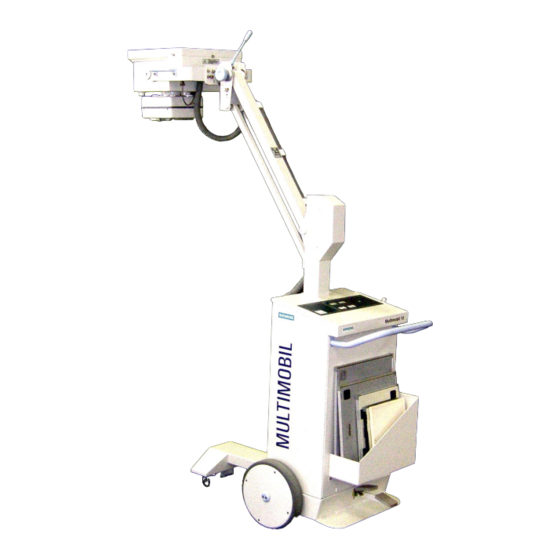
MULTIMOBIL 10
Troubleshooting Guide
Print No.: SPR8-X01.840.10.02.02
Replaces: SPR8-X01.840.10.01.02
SP
© Siemens AG 2003
The reproduction, transmission or
use of this document or its contents
is not permitted without express
written authority. Offenders will be
liable for damages. All rights,
including rights created by patent
grant or registration of a utility
model
_or_ design,_are_
reserved.
English
Doc. Gen. Date: 10.05
Advertisement
Table of Contents

Subscribe to Our Youtube Channel
Related Manuals for Siemens MULTIMOBIL 10


Summary of Contents for Siemens MULTIMOBIL 10
- Page 1 MULTIMOBIL 10 Troubleshooting Guide © Siemens AG 2003 The reproduction, transmission or use of this document or its contents is not permitted without express written authority. Offenders will be liable for damages. All rights, including rights created by patent grant or registration of a utility...
- Page 2 Multimobil 10 Service Instructions Version: 4.0 The reproduction, transmission or use of this document or its contents is not permitted without express written authority. Offenders will be liable damages. Siemens Ltd. Med Division India Version 4.0 Page 1 of 48...
- Page 3 Removing the top panel ........................16 3.1.2 Removing the Front cover....................... 17 3.1.3 Removing the X-ray source assembly....................17 ................. 18 HECKING THE LINE VOLTAGE FUSES AND Siemens Ltd. Med Division India Version 4.0 Page 2 of 48...
- Page 4 4.6.10 Code 10 : Rotating Anode not OK ....................45 4.6.11 Code 31 : No charging ....................... 46 4.6.12 Code 01 : Err signal on D950A active ..................48 Siemens Ltd. Med Division India Version 4.0 Page 3 of 48...
- Page 5 355V DC. After switching the unit OFF, it takes about 08 minutes for capacitors to discharge. The presence of DC voltage is indicated by Green LED V24 on D950A and also V1 ~ V12 LED’s on D970A / D971. Siemens Ltd. Med Division India Version 4.0 Page 4 of 48...
- Page 6 When unit is connected to 110 V line LN contactor does not function even though there is a variation in the supply voltage. Siemens Ltd. Med Division India Version 4.0 Page 5 of 48...
- Page 7 Release an exposure. The radiation LED will light up during exposure. The meter will read 57-63kV. Repeat with meter setting 77-150kV and exposure parameter setting, as 90kV 20mAs.The meter will read 85.5-94.5 kV. Siemens Ltd. Med Division India Version 4.0 Page 6 of 48...
- Page 8 1.12 Calibration : It is advisable to re-calibrate the unit in case of undershoot or overshoot observed in the mA wave shape. Recalibration is required when the single tank is replaced. Siemens Ltd. Med Division India Version 4.0 Page 7 of 48...
- Page 9 1.14 Safety notes and protective measures Refer to the General safety note in Chapter on Installation. Before working on the open MULTIMOBIL 10, switch off the unit with the power switch at the control panel, the MCB in off position and remove the Mains cable from socket.
- Page 10 Legal regulations may contain special prescriptions concerning the disposal of this product. In order to avoid environmental damage and/or personal injury, please inform SIEMENS Customer Service if you want to put the unit out of operation and dispose it. Radioprotection Material Lead in X-ray tube assembly and in Collimator 3 kg.
- Page 11 Check function of locking lever and cap screw on the X-ray tube Check the legibility of the labels according to those in section Location of Labels. If any labels require to be replaced, please notify Siemens customer service. 1.21.3 Performance Check (Every Six months) Check counterbalancing of the support arm at each position.
- Page 12 Note : Annual Maintenance must be performed as per the guidelines described in the Maintenance section. Notify Siemens Customer Service if you do not have a maintenance contract. 1.22 Program Modes for servicing. To put the unit into service mode, Short the ST link on the D915 and put ON the unit.Use the Kv+ and Kv- switches to select the required program from 1 to 7.
- Page 13 1.22.7 Program 7 : To set the max.inverter firing frequency(REG). Select the program seven in service mode and the display will read as below On activation of this program by pressing the DL-serv switch , the display indicates Siemens Ltd. Med Division India Version 4.0 Page 12 of 48...
- Page 14 Service Instructions Press the Radiographic exposure switch and monitor REG on Digital storage Oscilloscope. The display indicates Adjust REG for 15 kHz ±0.5kHz by using P4 on D915 card. Siemens Ltd. Med Division India Version 4.0 Page 13 of 48...
- Page 15 J12.8 and J12.10 on D915 cross 4.5V, Code is displayed. Iheiz > Imax OR JR > JRmax Maximum value of Iheiz above which Code will be displayed is 7 A (3.5V). Siemens Ltd. Med Division India Version 4.0 Page 14 of 48...
- Page 16 Integrator. Termination I > Iheiz Same as Code 04, but during Exposure. Maximum Preparation Time This Code is displayed if First step is pressed for more than 15 sec. Siemens Ltd. Med Division India Version 4.0 Page 15 of 48...
- Page 17 Removing the top panel, front cover and X-ray source assembly 3.1.1 Removing the top panel Turn off the Multimobil 10,disconnect the mains chord and wind the cord around the cable holder. Lower the X-ray source assembly to transport position. Lock the Multimobil 10 by applying the brake.
- Page 18 Place the front cover on a soft bedding. 3.1.3 Removing the X-ray source assembly. Turn off the Multimobil 10,disconnect the mains chord and wind the cord around the cable holder. Lower the X-ray source assembly to transport position. Lock the Multimobil 10 by applying the brake.
- Page 19 Note : If the Unit cannot be switched ON Check Supply at Mains socket. Check Continuity of mains cable with the Plug pins. Check Over Current Protective devices U1 & U2. Switch the Unit OFF. Siemens Ltd. Med Division India Version 4.0 Page 18 of 48...
- Page 20 Dgnd Input -nc- -nc- Dgnd Input DC supply Input + 5V DC supply Input +15V Agnd Input DC supply Input -15V - nc - = No Connection Siemens Ltd. Med Division India Version 4.0 Page 19 of 48...
- Page 21 Note: Preheat value is parameter (kV & mAs) specific. Just observe the change in level on preheating step. Checking the high voltage kVsoll and kVist Connect oscilloscope to D915.TP.KVS & D915.TP.KV Turn the unit ON. Trigger an exposure with the default values. Siemens Ltd. Med Division India Version 4.0 Page 20 of 48...
- Page 22 Connect mAs meter to “mAs +/ mAs-” on D800 PCB. Turn the Unit ON. Trigger the following exposures: Setting at control panel Valid mAs values 60kV,16mAs 15.5−16.5 mAs 60kV,100mAs 96−104 mAs 100kV,50mAs 48−52 mAs Siemens Ltd. Med Division India Version 4.0 Page 21 of 48...
- Page 23 (X1, X2, Y1, Y2) as shown. Determine the total deviations in the X and Y direction (ignore the +/- signs). Both, length deviation (ΣY) and width deviation (ΣX) must be less than 1.6 cm. Siemens Ltd. Med Division India Version 4.0 Page 22 of 48...
- Page 24 To replace the single tank, remove it from the mobile stand as follows: Move the arm system in the lowest (parking) position and check if the safety locking has engaged. The arm cannot be moved upwards any longer. Siemens Ltd. Med Division India Version 4.0 Page 23 of 48...
- Page 25 Take out the defective lamp and replace it by a new lamp. Caution : Do not touch the glass envelope with your bare fingers. Check functioning of the lamp. Siemens Ltd. Med Division India Version 4.0 Page 24 of 48...
- Page 26 THEN REPLACE D936 REPLACE D936 ELSE Relay K5 and then K4 on REPLACE D801. ELSE D801 ON REPLACE D801 Check 220V on D801X50.1-X50.3 Contactors NS,CS Ensure relays K4,CS1 operates? are operating. Siemens Ltd. Med Division India Version 4.0 Page 25 of 48...
- Page 27 Service Manual Service Instructions Measure voltages at X1.1 and X1.4 of D801 should be 230v~ Stop Siemens Ltd. Med Division India Version 4.0 Page 26 of 48...
- Page 28 ERRORS PAGE 25 PRESS RADIOGRAPHIC FIRST STEP. FILAMENT BOOSTING ? PRESS RADIOGRAPHIC SECOND STEP. RADIAGRAPHIC EXPOSURE INITIATED EXPOSURE ERROR ? GO TO EXPOSURE GO TO EXPOSURE ERRORS ERRORS PAGE 31 Siemens Ltd. Med Division India Version 4.0 Page 27 of 48...
- Page 29 Service Manual Service Instructions Contd…. +15V SUPPLY TO SIGNAL ON J36.15 ON RADIOGRAPHIC SWITCH D915 OK ? REPLACE RADIOGRAPHIC REPLACE D915 PCB RELEASE SWITCH STOP Siemens Ltd. Med Division India Version 4.0 Page 28 of 48...
- Page 30 ANY ERROR ERRORS PAGE 25 ERRORS” REPLACE D915 AND CALIBRATE THE UINT DISPLAYS STABLE KV,mAS ? GO TO STANDBY ERRORS GO TO STANDBY ERRORS PAGE 26 CONFIRM STANDBY PARAMETERS STOP Siemens Ltd. Med Division India Version 4.0 Page 29 of 48...
- Page 31 4.4.3 Code 97 ( mA FAILURE) ADJUST PRESET P6 ON D915 START CONFIRM 230v SUPPLY SWITCH ON THE UNIT X15 CONNECTOR SUPPLY OK ? REPLACE D980 ERROR CONTINUES REPLACE D915 PCB STOP Siemens Ltd. Med Division India Version 4.0 Page 30 of 48...
- Page 32 & SWITCH ON THE UNIT MEASURE +15 V ON X15 CONNECTOR VOLTAGE= 13.5 TO 16.5 V ? ADJUST BY PRESET ON D980. ELSE REPLACE D915 PCB REPLACE D980 PCB STOP Siemens Ltd. Med Division India Version 4.0 Page 31 of 48...
- Page 33 MONITOR I RMS ON D915 I RMS = 0.6V +/- 0.1 Is Filament ON ? Fil pulses at ADJUST BY PRESET P5 J22.15 & J22.16 of D915? Replace D801 REPLACE D915 PCB STOP Siemens Ltd. Med Division India Version 4.0 Page 32 of 48...
- Page 34 (ON D915 & D800) ARE PROPER (NO SPIKES) CONNECTED CONNECTION PROPERLY ? SWITCH OFF THE UNIT R=20 Kohms AT X8.1,X8.2 & X8.3 REPLACE D800 PCB ON THE SINGLE TANK. REPLACE D915 STOP Siemens Ltd. Med Division India Version 4.0 Page 33 of 48...
- Page 35 REPLACE D915 REPLACE D915 SWITCH OFF THE UNIT R=20 OHM AT X8.5 & X8.6 REPLACE D800. IF THE ERROR CONTINUES, REPLACE SINGLE TANK AND CALIBRATE THE UNIT. STOP STOP Siemens Ltd. Med Division India Version 4.0 Page 34 of 48...
- Page 36 MONITOR VP=15V ON D801. AND REPLACE D801 IF FOUND FAULTY. CHECK IGBTs AND REPLACE IF FOUND ERR/ SIGNAL SHORTED. OBTAINED FROM D960 ELSE REPLACE IGBT IN STBY MODE MODULE. REPLACE D915 STOP Siemens Ltd. Med Division India Version 4.0 Page 35 of 48...
- Page 37 SWITCH ON THE UNIT ENSURE J34 IC ON D915 IS WORKING IC FAULT ? SWITCH OFF & WAIT FOR 5 SEC IGBTS SHORTED? REPLACE IGBTs REPLACE D915 ELSE REPLACE IGBT MODULE STOP Siemens Ltd. Med Division India Version 4.0 Page 36 of 48...
- Page 38 PRESS DL_SERV KEY AND THEN ON SINGLE TANK EXPOSURE RELEASE SWITCH MONITOR REG AND SET THE ERROR CONTINUES FREQUENCY TO 15KHz. BY VARYING POT P4 REPLACE SINGLE TANK STOP Siemens Ltd. Med Division India Version 4.0 Page 37 of 48...
- Page 39 IS JR>JRmax ? MONITOR I FOR PULSES REDUCE OVERSHOOTS REPLACE D801 PCB IN JR BY PRESET P5 ELSE REPLACE D915 TAKE AN EXPOSURE ERROR CONTINUES ? REPLACE D915 PCB STOP Siemens Ltd. Med Division India Version 4.0 Page 38 of 48...
- Page 40 TAKE AN EXPOSURE D950A PCB MONITOR DISP1 & DISP2 REPLACE THE PULSES,TAKE AN EXPOSURE CHARGER MODULE PULSES ? REPLACE D915 PCB U/V CURRENT W/F. REPLACE IGBT MODULE REPLACE SINGLE TANK STOP Siemens Ltd. Med Division India Version 4.0 Page 39 of 48...
- Page 41 Check Inverter ckt/ Inverter pulses/ Check and Resonance cap. C5. Voltage betw. X8.5 replace D800 if and X8.6 is OK? found fauly. Check and replace STOP D915 if found faulty Siemens Ltd. Med Division India Version 4.0 Page 40 of 48...
- Page 42 IT EQUAL TO mAS ADJUST FREQUENCY AT J1.9 BY VARYING P1 TAKE AN EXPOSURE AND NOTE THE TIME TIME EXCEEDS EXPOSURE TIME ? ERROR CONTINUES REPLACE D915 PCB STOP Siemens Ltd. Med Division India Version 4.0 Page 41 of 48...
- Page 43 Service Instructions 4.6.7 Code 18 : Premature termination of Exposure START PRESS KV mAs KEY. ERROR IS REMOVED. PRESS AND HOLD EXPOSURE RELEASE SWITCH TILL EXPOSURE GETS TERMINATED. STOP Siemens Ltd. Med Division India Version 4.0 Page 42 of 48...
- Page 44 MONITOR IH ON D915 PCB DECREASE BY VARYING POT P5 AND P6 IS THERE ANY SPIKE ? TAKE AN EXPOSURE REPLACE D801 ERROR CONTINUES ? REPLACE D915 PCB STOP Siemens Ltd. Med Division India Version 4.0 Page 43 of 48...
- Page 45 4.6.9 Code 22 : Maximum Preparation Time START ALLOW 2 TO 10 SEC TIME IN BETWEEN FIRST & SECOND STEP OF RADIOGRAPHY TAKE AN EXPOSURE ERROR CONTINUES REPLACE D915 PCB STOP Siemens Ltd. Med Division India Version 4.0 Page 44 of 48...
- Page 46 D915? Rot. Anode ckt OK? Replace D801 Check fuse F3 on D801 and replace if found Replace D915 faulty. If relay K2 on D801 doesn't operate,replace stop Siemens Ltd. Med Division India Version 4.0 Page 45 of 48...
- Page 47 Replace CS contactor Check V24 on D950A glows? Check Vc test point on D950A? Should be 3.3 Vdc. Replace D950A Check Fr1 test point on D950A? Should be 25 KHz frequency. Siemens Ltd. Med Division India Version 4.0 Page 46 of 48...
- Page 48 Service Manual Service Instructions Contd……. Check Vc on Check if X20 cable is D915? Should be OK.If found faulty 3.3V. replace the cable. Replace D915. Stop Siemens Ltd. Med Division India Version 4.0 Page 47 of 48...
- Page 49 4.6.12 Code 01 : Err signal on D950A active Start Is tp test point on D950A low? Replace D950A. Is Vc>3.35v (A test point on D950A?) Whether IGBT V3 is Short circuited. Stop Siemens Ltd. Med Division India Version 4.0 Page 48 of 48...
Need help?
Do you have a question about the MULTIMOBIL 10 and is the answer not in the manual?
Questions and answers