Table of Contents
Advertisement
Quick Links
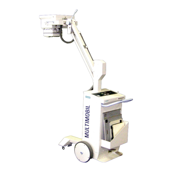
MULTIMOBIL 10
Installation Instructions
Print No.: SPR8-X01.812.10.02.02
Replaces: SPR8-X01.812.10.01.02
SP
© Siemens AG 2003
The reproduction, transmission or
use of this document or its contents
is not permitted without express
written authority. Offenders will be
liable for damages. All rights,
including rights created by patent
grant or registration of a utility
model
_or_ design,_are_
reserved.
English
Doc. Gen. Date: 10.05
Advertisement
Table of Contents

Related Manuals for Siemens MULTIMOBIL 10


Summary of Contents for Siemens MULTIMOBIL 10
- Page 1 MULTIMOBIL 10 Installation Instructions © Siemens AG 2003 The reproduction, transmission or use of this document or its contents is not permitted without express written authority. Offenders will be liable for damages. All rights, including rights created by patent grant or registration of a utility...
- Page 2 Multimobil 10 Installation Instructions Version: 4.0 The reproduction, transmission or use of this document or its contents is not permitted without express written authority. Offenders will be liable damages. Siemens Ltd. Med Division India Version 4.0 Page 1 of 12...
-
Page 3: Table Of Contents
SWITCHING THE UNIT ON ......................7 :.................... 8 ORMING OF THE APACITOR :..........................9 OLLIMATOR :........................... 10 OVEMENTS ..........................10 XPOSURE 2.4.1 Sample Exposure: ......................11 HANDING OVER MULTIMOBIL 10.................... 12 Siemens Ltd. Med Division India Version 4.0 Page 2 of 12... -
Page 4: Installation
The radiation indication lamp should light only when the exposure is released. In case the lamp lights in any other condition, the unit should be immediately switched off and SIEMENS SERVICE DEPARTMENT should be informed. Any change / or replacement in the unit must be carried out by the manufacturer or a person authorised by manufacturer ONLY. -
Page 5: Overload Protection
(except handles) indicates possible danger of upward force the order of 25kg, when the arm is released from its locked position. In such a situation, it is recommended to suspend the installation and contact FACTORY for further clarification. Siemens Ltd. Med Division India Version 4.0 Page 4 of 12... -
Page 6: Unpacking
Service Manual Installation Instructions Unpacking Siemens Ltd. Med Division India Version 4.0 Page 5 of 12... -
Page 7: Transport And Positioning Of Unit
Bleeder resistor to X9.D950A 3 pin connector discharge cable The max. Permissible resistance between the earthing terminal in the control and the single tank is less than 0.2 ohms. Siemens Ltd. Med Division India Version 4.0 Page 6 of 12... -
Page 8: Switching The Unit On
After set-up, initial hardware checks and capacitor bank fully charged to 355V DC the display changes to the default kV and mAs settings. The kV & mAs display and settings will now respond to the corresponding switches on the panel. Siemens Ltd. Med Division India Version 4.0 Page 7 of 12... -
Page 9: Forming Of The Capacitor Bank
ST link (jumper pin) on D915 PCB. Switch ON the MCB Switch the Generator ON by actuating momentarily Then the kV and mAs display read as shown in picture, if there are no initialisation Errors. Siemens Ltd. Med Division India Version 4.0 Page 8 of 12... -
Page 10: Collimator
Open collimator flaps to the maximum. The light will show square, sharp edges and clear cross wires. Close the flaps fully. The light field will show a small square. Siemens Ltd. Med Division India Version 4.0 Page 9 of 12... -
Page 11: Movements
: V23 Error indication : V24 In case of an error the corresponding code will be displayed on the seven-segment display. Refer the service instructions to rectify the error. Siemens Ltd. Med Division India Version 4.0 Page 10 of 12... -
Page 12: Sample Exposure
TP :kV and JR. Also note the T exp from kV waveform. Following should be the values. Kvist : 1v=20kV Texp = 100ms JR : (1V = 50mA) 3.2V Texp = 100ms Siemens Ltd. Med Division India Version 4.0 Page 11 of 12... -
Page 13: Handing Over Multimobil 10
Service Manual Installation Instructions 3 Handing Over Multimobil 10 Important: Hand over the machine after taking sample exposures: 1. Chest : 60KV,12.5 mAs ( +/- 1,2 points) 2. Skull : 70KV,25mAs(+/- 2 points) 3. Extremities : 42KV,6.4 mAs (+/- 2 points) 4.
Need help?
Do you have a question about the MULTIMOBIL 10 and is the answer not in the manual?
Questions and answers