Table of Contents

Related Manuals for Riken Keiki GX-Force


Summary of Contents for Riken Keiki GX-Force
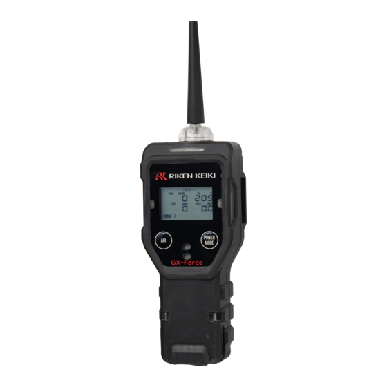
- Page 1 PT0E-2100 Portable Gas Detector GX-Force Operating Manual (PT0-210) 2-7-6 Azusawa, Itabashi-ku, Tokyo, 174-8744, Japan Phone : +81-3-3966-1113 Fax : +81-3-3558-9110 E-mail : intdept@rikenkeiki.co.jp Web site : https://www.rikenkeiki.co.jp/...
-
Page 2: Table Of Contents
Contents Contents 1 Product Overview ............................4 1-1 Introduction ............................... 4 1-2 Intended use ............................. 5 1-3 Checking the detection target gases and product type ................5 1-4 DANGER, WARNING, CAUTION, and NOTE ..................6 1-5 Checking standards and explosion-proof specifications ................7 2 Important Safety Information .......................... - Page 3 Contents 6-4 User mode settings ..........................53 6-4-1 Bump test ............................53 6-4-2 Gas adjustment ..........................53 6-4-3 Adjustment expiration setting ......................53 6-4-4 Bump test setting ..........................57 6-4-5 Alarm setpoint setting ........................65 6-4-6 Lunch break on/off .......................... 68 6-4-7 Confirmation beep setting .......................
-
Page 4: Product Overview
The product should be used only by fully-trained personnel. The maintenance procedures described in this manual should be performed only by fully-trained personnel. Any maintenance procedure not described in this manual must be performed by Riken Keiki or our certified service engineers. Please contact Riken Keiki. -
Page 5: Intended Use
1 Product Overview 1-2 Intended use 1-2 Intended use The product is a gas detector designed to measure the concentrations of chemicals in the air in working environments. It measures concentrations of toxic gases, combustible gases, and oxygen in the atmosphere and issues an alarm when preset alarm concentrations are reached, thereby alerting users to the hazards of explosion, gas poisoning, and oxygen deficiency. -
Page 6: Danger, Warning, Caution, And Note
1 Product Overview 1-4 DANGER, WARNING, CAUTION, and NOTE 1-4 DANGER, WARNING, CAUTION, and NOTE This operating manual uses the following categories to indicate potential damage/hazards if the user disregards the information provided and uses the product incorrectly: This indicates situations in which improper handling may result in fatal or DANGER serious injury or significant property damage. -
Page 7: Checking Standards And Explosion-Proof Specifications
1 Product Overview 1-5 Checking standards and explosion-proof specifications 1-5 Checking standards and explosion-proof specifications The product specifications will vary depending on the specific standards and explosion-proof certification. Check the actual product specifications before use. For CE/UKCA marking models, refer to the ‘Declaration of Conformity’... -
Page 8: Important Safety Information
2 Important Safety Information 2-1 Danger information Important Safety Information To maintain the performance of the product and to ensure safe use, always observe the following DANGER, WARNING, and CAUTION instructions. 2-1 Danger information DANGER Explosion-proofing Do not modify or alter the circuits or configuration. ... -
Page 9: Warnings
WARNING If an abnormality occurs Contact Riken Keiki immediately. Visit our website for information on the nearest Riken Keiki office. Website: https://www.rikenkeiki.co.jp/ Sensor handling Never attempt to disassemble the electrochemical type sensor inside the product. Contact with the electrolyte inside the sensor may result in skin inflammation. -
Page 10: Precautions
2 Important Safety Information 2-3 Precautions 2-3 Precautions CAUTION Do not use the product in locations where it may be exposed to oil or chemicals, etc. ・ Avoid using the product in locations where it may be splashed with oil, chemicals, or other liquids. ・... - Page 11 After a period of extended storage, be sure to perform gas adjustment before resuming use. For information on readjustment including gas adjustment, please contact Riken Keiki. 11 / 110...
-
Page 12: Safety Information
Observe the following points to ensure performance as an explosion-proof product: Product overview The GX-Force can be equipped with up to three types of sensors to detect up to four different gas types. The GX-Force can be used to detect combustible gases (%LEL), oxygen (O ), hydrogen sulfide (H and carbon monoxide (CO). - Page 13 2 Important Safety Information 2-4 Safety information Do not charge in hazardous areas. Charge the battery using the dedicated AC adapter, an IEC 60950 certified SELV power supply, or IEC 62368-1 certified ES1 power supply. When measuring oxygen concentrations, use the product only to detect leaks of mixtures of air and combustible gas or toxic gas.
- Page 14 2 Important Safety Information 2-4 Safety information Product code INST. No. 0000 A: Year of manufacture (0 - 9) B: Month of manufacture (1 - 9 for Jan. - Sep.; XYZ for Oct., Nov., Dec.) C: Manufacturing lot D: Serial number E: Factory code 2-7-6 Azusawa, Itabashi-ku, Tokyo, 174-8744, Japan Phone: +81-3-3966-1113...
-
Page 15: Product Configuration
3-1 Main unit and accessories Open the box and packaging and inspect the product and accessories. If anything is missing, contact Riken Keiki. 3-1-1 Main unit For detailed information on the names and functions of product parts and the LCD display, refer to ‘3-2 Part names and functions’. -
Page 16: Accessories
3 Product Configuration 3-1 Main unit and accessories 3-1-2 Accessories <Japan EX specifications> AC adapter Tapered nozzle ×1 ×1 Hand strap Product Operating Warranty ×1 warranty Manual < ATEX/UKEX/IECEx specifications> Product warranty Sensor warranty Operating Manual 3-1-3 Optional accessories AC adapter ×1 Tapered nozzle ×1... - Page 17 USB cable ・ For connecting to the PC when using the data logger management program Type-A - Type-C ・ The cable is 1 m long. ×1 Data logger management program CD- ROM (SW-GX-Force) ×1 Various filters, etc. 17 / 110...
-
Page 18: Part Names And Functions
3 Product Configuration 3-2 Part names and functions 3-2 Part names and functions This section describes the names and functions of the various parts of the main unit and the LCD display. 3-2-1 Main unit (10) (11) (12) Name Main function LCD display Displays the gas concentration and other information. - Page 19 3 Product Configuration 3-2 Part names and functions Name Main function Flashes in red when an alarm occurs. Alarm LED arrays The LEDs on the left and right also flash red if measurement is not currently underway. Light Lights up when the light is turned on. Contains a dust filter.
-
Page 20: Lcd Display
3 Product Configuration 3-2 Part names and functions 3-2-2 LCD display Name Main function Operating status icon Indicates the product operating status. Blinks when normal. Clock display Displays the time. Combustible gas concentration Displays gas concentrations. Oxygen concentration The concentration reading is updated every five seconds for combustible gases. -
Page 21: Alarm Activation
4 Alarm Activation 4-1 Gas alarm types Alarm Activation 4-1 Gas alarm types A gas alarm is triggered if the concentration of the detected gas reaches or exceeds the alarm setpoints shown in the following table. (Self-latching) Gas alarm types include the first alarm (WARNING), second alarm (ALARM), third alarm (ALARM H), TWA alarm, STEL alarm, OVER alarm (over scale), and M OVER alarm (minus sensor failure). -
Page 22: Gas Alarm Patterns
MODE button when a gas alarm is triggered. The buzzer will sound once again if a new gas alarm is triggered after you stop the first buzzer. This function can be enabled/disabled in the optional data logger management program (SW-GX-Force). ... - Page 23 4 Alarm Activation 4-3 Gas alarm patterns <Gas alarm display> If a gas alarm occurs, the alarm type is indicated at the bottom of the screen and the corresponding gas concentration, gas name, and unit displays blink. If the detection range is exceeded (over scale), [OVER] appears at the bottom of the screen and [∩∩∩] blinks in the gas concentration display area.
-
Page 24: Fault Alarm Patterns
Pump abnormality Low flow rate abnormality If a fault alarm occurs, determine the cause and take appropriate action. If the problem lies with the product and the fault occurs repeatedly, contact Riken Keiki immediately. NOTE For more information on malfunctions (error messages), refer to ‘9 Troubleshooting’. -
Page 25: Usage Instructions
5 Usage Instructions 5-1 Usage note Usage Instructions 5-1 Usage note The operating precautions apply to both first-time users and those who have previously used the product. Ignoring these precautions may damage the product and result in inaccurate gas detection. 5-2 Preparations for startup Check the following before starting gas detection: ... -
Page 26: Charging The Lithium Ion Battery
5 Usage Instructions 5-2 Preparations for startup 5-2-1 Charging the lithium ion battery Before using the product for the first time or if battery level of the lithium ion battery is low, charge as described below. DANGER Charge in a location free of hazards. ... - Page 27 5 Usage Instructions 5-2 Preparations for startup Plug the charger into the outlet. When the charger is connected, the charging indicator lamp lights up in green. When charging starts, the lamp lights up in orange. (Full charge requires about 10 hours at maximum.) Once charging is completed, the charging indicator lamp lights up in green.
-
Page 28: Startup Procedure
5 Usage Instructions 5-3 Startup procedure 5-3 Startup procedure When the power is turned on, various settings including the date and time and alarm setpoints are displayed, and then the measurement mode screen is displayed. 5-3-1 Turning on the power Hold down the POWER button (for at least three seconds) until the buzzer blips. -
Page 29: Screen Transition From Powering On To Measurement Mode
5 Usage Instructions 5-3 Startup procedure 5-3-2 Screen transition from powering on to measurement mode When the power is turned on, the LCD display changes automatically as shown below, then the product switches to measurement mode. <Display examples: Default settings> (Approx. 40 seconds) Maintenance notification Gas adjustment expiration Date and time display... - Page 30 After the alarm is reset, [- - - -] appears in the concentration display area of the gas for which the sensor abnormality occurred, and detection will not be possible for that gas type. Contact Riken Keiki immediately. ...
- Page 31 5 Usage Instructions 5-3 Startup procedure NOTE If an abnormality arises in the built-in clock, a fault alarm ([FAIL CLOCK]) may be triggered. If this occurs, press the MODE button. The fault alarm will be temporarily reset, and measurement will be started with the clock time remaining incorrect.
-
Page 32: Fresh Air Adjustment
5 Usage Instructions 5-4 Fresh air adjustment 5-4 Fresh air adjustment Fresh air adjustment refers to zero adjustment required to ensure accurate measurement of gas concentrations. WARNING When fresh air adjustment is performed in the atmosphere, check the atmosphere for freshness before starting. -
Page 33: Gas Detection
5 Usage Instructions 5-5 Gas detection 5-5 Gas detection DANGER If measuring inside manholes or enclosed spaces, never lean over or look into the manhole or enclosed space. There is a danger that oxygen-deficient air or other gases may be discharged from such locations. -
Page 34: Basic Operating Flow
5 Usage Instructions 5-5 Gas detection 5-5-1 Basic operating flow Turn on the power to proceed to the measurement mode screen. <Snap log record> <Fresh air adjustment> <Display mode> Hold down Hold down <Measurement mode> <Gas alarm state> <Fault alarm state> Measured value blinking... -
Page 35: Measurement Mode
5 Usage Instructions 5-5 Gas detection 5-5-2 Measurement mode In measurement mode, read the values on the LCD display. Combustible gas Oxygen (%LEL) Carbon Hydrogen monoxide sulfide Display example CAUTION Note that if combustible gas sensors are used in an environment where silicone compounds, halides, high-concentration sulfides, or high-concentration solvent gases are present, sensor life may be reduced, sensitivity to combustible gases may deteriorate, and accurate readings may not be obtained. - Page 36 5 Usage Instructions 5-5 Gas detection The carbon monoxide sensor (ESR-A1CP) includes a correction function to reduce interference due to hydrogen. This function works for hydrogen concentrations up to 2,000 ppm. If hydrogen is detected at a concentration of 2,000 ppm or higher, [H2] and [rich] are displayed alternately in the concentration display area.
-
Page 37: Snap Log Recording
5 Usage Instructions 5-5 Gas detection 5-5-3 Snap log recording Instantaneous concentration values can be recorded for user-specified gases while measurement is in progress. Up to 256 items can be recorded in the snap log. When the maximum number of items is reached, the oldest data is overwritten by new data. -
Page 38: Turning Off The Power
5 Usage Instructions 5-6 Turning off the power 5-6 Turning off the power CAUTION If the concentration display does not return to zero (or 20.9 % for the oxygen concentration display) after measurement is completed, allow the product to suck in fresh air until the display returns to zero before turning off the power. -
Page 39: Setting Procedure
6 Setting Procedure 6-1 Display mode Setting Procedure 6-1 Display mode Display mode lets users review and change various display settings and perform other operations. Changed settings are saved. 6-1-1 Switching to display mode Press the MODE button in measurement mode. Pressing the MODE button displays the various setting item screens in sequence. -
Page 40: Contents Displayed In Display Mode
6 Setting Procedure 6-1 Display mode 6-1-2 Contents displayed in display mode Setting item Display contents LCD display Reference (Screen notation) Light on/off Turns the light on and off. ‘6-2-1 Light on/off’ ([LIGHT]) Displays the maximum gas concentration (or minimum ‘6-2-2 Clearing PEAK value display oxygen concentration) - Page 41 6 Setting Procedure 6-1 Display mode Setting item Display contents LCD display Reference (Screen notation) Snap log data display Displays the recorded gas ‘6-2-6 Snap log ([REC.DATA]) concentration. data display’ Date and time and Displays the date, time, and temperature display ----- temperature.
-
Page 42: Display Mode Settings
6 Setting Procedure 6-2 Display mode settings 6-2 Display mode settings You can check and change settings by switching from measurement mode to display mode. 6-2-1 Light on/off Turns the light on and off. The light will go out automatically approximately two minutes after it is turned on. Press the MODE button in measurement mode to display the LIGHT screen. -
Page 43: Combustible Gas Conversion Setting
6 Setting Procedure 6-2 Display mode settings 6-2-3 Combustible gas conversion setting Combustible gas measurements can be displayed as a concentration of a gas preregistered in the product. The following combustible gases can be converted: <Combustible gas conversion list> Calibration gas Conversion Gas name conversion... - Page 44 If the screen shown on the right is displayed, the conversion function can be used only for those gas types marked “〇” in the “Conversion when conversion is restricted” column. To continue to use the conversion function for gas types marked “×”, contact Riken Keiki. NOTE ...
- Page 45 6 Setting Procedure 6-2 Display mode settings Press the MODE button several times in measurement mode to display the LIST screen. Press the AIR button to select the combustible gas to be converted. Pressing the AIR button cycles the display through the list of combustible gases.
-
Page 46: Adjustment Data Display
6 Setting Procedure 6-2 Display mode settings 6-2-4 Adjustment data display Displays the date on which gas adjustment was performed. NOTE This is displayed with ATEX/UKEX/IECEx specifications. Adjustment data is not displayed if the adjustment expiration display setting is disabled in user mode. -
Page 47: Bump Test Data Display
6 Setting Procedure 6-2 Display mode settings 6-2-5 Bump test data display Displays the date on which the bump test was performed. NOTE Bump test data is not displayed if the bump test expiration display setting is disabled in user mode. The default setting is [OFF]. -
Page 48: Snap Log Data Display
6 Setting Procedure 6-2 Display mode settings 6-2-6 Snap log data display Snap log data is data for gas concentrations recorded during measurement. Select the recorded date, time, and memory number to display the corresponding gas concentration. NOTE For information on how to record snap log data, refer to ‘5-5-3 Snap log recording’. Press the MODE button several times in measurement mode to display the REC.DATA screen. -
Page 49: Alarm Setpoint Display
6 Setting Procedure 6-2 Display mode settings 6-2-7 Alarm setpoint display This allows alarm setpoints to be displayed and testing of LED, buzzer, and vibrator operations. NOTE [TWA] and [STEL] are displayed only on models that detect gases other than combustible gases and oxygen. -
Page 50: User Mode
6 Setting Procedure 6-3 User mode 6-3 User mode User mode lets you set the date and time, alarm setpoints, and other settings. 6-3-1 Switching to user mode With the power turned off, press the AIR button and POWER button at the same time. Release the buttons when the buzzer blips. -
Page 51: User Mode Setting Items
6 Setting Procedure 6-3 User mode 6-3-2 User mode setting items Setting item (Screen notation) LCD display Reference Bump test ([BUMP]) ‘6-4-1 Bump test’ Gas adjustment ([GAS CAL]) ‘6-4-2 Gas adjustment’ Adjustment expiration setting ([CAL SET]) ‘6-4-3 Adjustment expiration setting’ * Displayed with ATEX/UKEX/IECEx specifications only Bump test setting ([BUMP.SET]) - Page 52 6 Setting Procedure 6-3 User mode Setting item (Screen notation) LCD display Reference Key operation tone on/off ([KEY.TONE]) ‘6-4-9 Key operation tone on/off’ Display mode item display on/off ‘6-4-10 Display mode item display on/off’ ([DISP.SET]) Zero suppression on/off ([ZERO.SUP]) ‘6-4-11 Zero suppression on/off’ Zero follower on/off ([ZERO.FLW]) ‘6-4-12 Zero follower on/off’...
-
Page 53: User Mode Settings
The product can be adjusted using AUTO adjustment with preset gas concentrations in addition to fresh air adjustment. Gas adjustment requires dedicated tools and a calibration gas. Contact Riken Keiki. The product automatically switches to measurement mode following a successful gas adjustment. - Page 54 6 Setting Procedure 6-4 User mode settings Adjustment expiration setting is configured in [CAL SET] in user mode. The following menu displayed in [CAL SET] allows individual items to be set. <[CAL SET] menu> User mode menu [CAL SET] [CAL.RMDR] [CAL.INT] [CAL.EXPD] [ESCAPE]...
- Page 55 6 Setting Procedure 6-4 User mode settings NOTE To exit the [CAL SET] menu, press the AIR button to select [ESCAPE], then press the MODE button. The display returns to the user mode menu. <Adjustment expiration display on/off> This enables and disables the adjustment expiration display. Press the AIR button on the [CAL SET] menu to select [CAL.RMDR], then press the MODE button.
- Page 56 6 Setting Procedure 6-4 User mode settings <Operation setting after adjustment expiration> This lets you select the operation performed after adjustment has expired. Press the AIR button on the [CAL SET] menu to select [CAL.EXPD], then press the MODE button. Press the AIR button to select the operation performed after adjustment has expired.
-
Page 57: Bump Test Setting
6 Setting Procedure 6-4 User mode settings 6-4-4 Bump test setting Bump test setting is configured in [BUMP.SET] in user mode. The following menu displayed in [BUMP.SET] allows individual items to be set. <[BUMP.SET] menu> User mode menu [BUMP.SET] [SETTING] [GAS.TIME] [CHECK] [CAL.TIME]... - Page 58 6 Setting Procedure 6-4 User mode settings Screen notation LCD display Reference [BMP.INT] ‘<Bump test expiration interval selection>’ ‘<Operation setting after bump test [BMP.EXPD] expiration>’ [ESCAPE] ----- NOTE To exit the [BUMP.SET] menu, press the AIR button to select [ESCAPE], then press the MODE button.
- Page 59 6 Setting Procedure 6-4 User mode settings <Bump time selection> This sets the time for introducing the test gas. Press the AIR button on the [BUMP.SET] menu to select [SETTING], then press the MODE button. The [SETTING] menu is displayed. Press the AIR button to select [GAS.TIME], then press the MODE button.
- Page 60 6 Setting Procedure 6-4 User mode settings <Bump tolerance selection> This sets the threshold for checking the test gas. Gases other than oxygen: Adjustment concentration ± (adjustment concentration bump tolerance) Oxygen: Adjustment concentration ± (difference between adjustment concentration and 20.9 % ...
- Page 61 6 Setting Procedure 6-4 User mode settings <Gas adjustment time selection after bump test> This selects the time for gas adjustment after a bump test has failed. Press the AIR button on the [BUMP.SET] menu to select [SETTING], then press the MODE button. The [SETTING] menu is displayed.
- Page 62 6 Setting Procedure 6-4 User mode settings <Gas adjustment after bump test on/off > This enables and disables the function for automatic gas adjustment if a bump test fails. Press the AIR button on the [BUMP.SET] menu to select [SETTING], then press the MODE button. The [SETTING] menu is displayed.
- Page 63 6 Setting Procedure 6-4 User mode settings <Bump test expiration display on/off> This enables and disables the bump test expiration display. Press the AIR button on the [BUMP.SET] menu to select [BMP.RMDR], then press the MODE button. Press the AIR button to enable or disable the bump test expiration display.
- Page 64 6 Setting Procedure 6-4 User mode settings <Operation setting after bump test expiration> This selects the operation after the bump test expiration display. Press the AIR button on the [BUMP.SET] menu to select [BMP.EXPD], then press the MODE button. Press the AIR button to select the operation performed after bump test expiration.
-
Page 65: Alarm Setpoint Setting
6 Setting Procedure 6-4 User mode settings 6-4-5 Alarm setpoint setting Sets the first, second, and third alarm setpoints and STEL and TWA alarm setpoints, and also allows the setpoint settings to be reset to their default values. <Alarm setpoint setting> Alarm setpoints can be set using one-digit units. - Page 66 For more information on how to reset alarm setpoints, refer to ‘<Resetting alarm setpoints>’ on the next page. The alarm setpoint reset ([DEF.ALMP]) screen may not appear if the product is not set correctly. If this occurs, contact Riken Keiki. ...
- Page 67 6 Setting Procedure 6-4 User mode settings <Resetting alarm setpoints> This restores alarm setpoints to their default settings. Press the AIR button on the user mode menu to select [ALARM-P], then press the MODE button. Press the AIR button several times to select [DEF.ALMP], then press the MODE button.
-
Page 68: Lunch Break On/Off
6 Setting Procedure 6-4 User mode settings 6-4-6 Lunch break on/off This lets you enable and disable the lunch break function. The lunch break function retains TWA and PEAK values from the last time the power was turned off and loads them to continue measurement the next time the power is turned on. -
Page 69: Confirmation Beep Setting
6 Setting Procedure 6-4 User mode settings 6-4-7 Confirmation beep setting This function provides an audible indication of whether the product is operating normally. The buzzer sounds at preset intervals while measurement is underway. [BMP/CAL], [ALM.ALRT], and [B/C/ALM] can also be set to use the following functions: 1. - Page 70 6 Setting Procedure 6-4 User mode settings Confirmation beep setting is configured in [BEEP] in user mode. The following menu displayed in [BEEP] allows individual items to be set. <[BEEP] menu> User mode menu [BEEP] [BEEP.SEL] [BEEP.INT] [ESCAPE] <[BEEP] menu selection> Press the AIR button on the user mode menu to select [BEEP], then press the MODE button.
- Page 71 6 Setting Procedure 6-4 User mode settings <Beep operation setting> This lets you set the confirmation beep operation. However, altering the beep operation setting will stop the [BMP/CAL], [ALM.ALRT], and [B/C/ALM] operations. Press the AIR button in the [BEEP] menu to select [BEEP.SEL], then press the MODE button.
-
Page 72: Lcd Lighting Time Setting
6 Setting Procedure 6-4 User mode settings 6-4-8 LCD lighting time setting The duration for which the LCD display backlight remains lit can be set. Press the AIR button on the user mode menu to select [BL TIME], then press the MODE button. Press the AIR button to select the backlight lighting time. -
Page 73: Display Mode Item Display On/Off
6 Setting Procedure 6-4 User mode settings 6-4-10 Display mode item display on/off This lets you set whether display mode items that can be set are displayed or hidden. When disabled, items such as combustible gas conversion setting ([HC GAS]) are not displayed in display mode. -
Page 74: Zero Suppression On/Off
6 Setting Procedure 6-4 User mode settings 6-4-11 Zero suppression on/off This enables and disables zero suppression (or air suppression with an oxygen sensor). Gas detection sensors are affected by environmental factors such as temperature and humidity characteristics. They are also substantially affected by the interference of the target gas. Environmental and interference effects may cause the product reading to fluctuate around zero. -
Page 75: Zero Follower On/Off
6 Setting Procedure 6-4 User mode settings 6-4-12 Zero follower on/off This enables and disables the zero follower function. The sensors used in the product may exhibit sensitivity variations when used for extended periods. The zero follower function stabilizes the zero point by adjusting reading fluctuations at the zero point that result from extended periods of use. -
Page 76: Date And Time Setting
6 Setting Procedure 6-4 User mode settings 6-4-13 Date and time setting The internal clock date (year, month, day) and time (hours and minutes) can be set. Press the AIR button on the user mode menu to select [DATE], then press the MODE button. Press the AIR button to select the required setting item, then press the MODE button. -
Page 77: Rom/Sum Display
6 Setting Procedure 6-4 User mode settings <Accessing user mode when password-protected> With the power turned off, press the AIR button and POWER button at the same time. Release the buttons when the buzzer blips. The password input screen is displayed. Press the AIR button to select from [0] - [9], then press the MODE button. -
Page 78: Maintenance
Check the gas alarm with a calibration gas. - - 〇 WARNING If you encounter a product abnormality, contact Riken Keiki immediately. NOTE Span adjustment requires dedicated tools and preparation of a calibration gas. Always contact Riken Keiki for span adjustment. ... -
Page 79: Maintenance Service
Our certified service engineers have expert knowledge of the dedicated tools used for these services, along with expertise in products. Please take advantage of the Riken Keiki maintenance service to maintain safe operation of the product. The major maintenance service items are as follows. Contact Riken Keiki for more information. -
Page 80: Gas Adjustment
7-2 Gas adjustment The product can be adjusted using AUTO adjustment with preset gas concentrations in addition to fresh air adjustment. Span adjustment requires a calibration gas. Contact Riken Keiki. CAUTION Do not use lighter gas to check the sensitivity of the product. Constituents in lighter gas may degrade sensor performance. - Page 81 7 Maintenance 7-2 Gas adjustment <Gas supply method> Connect the gas sampling bag as shown in the figure below to introduce gas, and wait 60 seconds after the reading increases before adjusting. <When open to the atmosphere> <When using gas recovery> Gas sampling bag Gas sampling bag Gas sampling...
-
Page 82: Gas Adjustment Setting
7 Maintenance 7-2 Gas adjustment 7-2-2 Gas adjustment setting Gas adjustment setting is configured in [GAS CAL] in user mode. The following menu displayed in [GAS CAL] allows fresh air adjustment and AUTO adjustment to be performed, as well as AUTO adjustment setting to be configured. <[GAS CAL] menu>... - Page 83 7 Maintenance 7-2 Gas adjustment [ESCAPE] ----- NOTE To exit the [GAS CAL] menu, press the AIR button to select [ESCAPE], then press the MODE button. The display returns to the user mode menu. To exit the [AUTO.CAL] menu, press the AIR button to select [ESCAPE], then press the MODE button.
-
Page 84: Fresh Air Adjustment
7 Maintenance 7-2 Gas adjustment 7-2-3 Fresh air adjustment WARNING When fresh air adjustment is performed in the atmosphere, check the atmosphere for freshness before starting. The presence of interference gases will make it impossible to perform zero adjustment correctly and potentially result in hazardous conditions in the event of actual gas leaks. CAUTION ... -
Page 85: Auto Adjustment
7 Maintenance 7-2 Gas adjustment The current concentration appears after fresh air adjustment and the display returns to the screen in Step 1. [FAIL] is displayed if adjustment was unsuccessful. [END] appears and the display returns to the screen in Step 1. NOTE ... - Page 86 7 Maintenance 7-2 Gas adjustment AUTO adjustment is performed. [PASS] is displayed if AUTO adjustment was successful. [FAIL] is displayed if adjustment was unsuccessful. The concentration after AUTO adjustment is displayed. With Japan EX specifications, the concentration and sensor reserve value after AUTO adjustment are displayed after AUTO adjustment has been successfully performed.
- Page 87 “〇” in the “Conversion when conversion is restricted” column. To continue to use the conversion function for gas types marked “×”, contact Riken Keiki. 87 / 110...
-
Page 88: Auto Adjustment Setting
7 Maintenance 7-2 Gas adjustment 7-2-5 AUTO adjustment setting This sets the AUTO adjustment cylinders and adjustment concentrations. <AUTO adjustment cylinder settings> Set the gas groups (cylinders) for calibration. The cylinders can be set as A - E. Press the AIR button on the [GAS CAL] menu to select [AUTO.CAL], then press the MODE button. - Page 89 7 Maintenance 7-2 Gas adjustment <AUTO adjustment calibration gas concentration selection> Calibration gas concentrations for AUTO adjustment can be set for each sensor. The calibration gas concentrations can be set in one-digit units within the setting range. <Calibration gas concentration setting ranges> Detection target Lower Upper...
- Page 90 7 Maintenance 7-2 Gas adjustment Press the AIR button to select the adjustment concentration, then press the MODE button. [END] appears and the display returns to the screen in Step 3. To exit setting, press the AIR button to select [ESCAPE], then press the MODE button.
-
Page 91: Bump Test
7 Maintenance 7-3 Bump test 7-3 Bump test The product includes a function for performing a bump test (function check). 7-3-1 Performing bump test A bump test can be performed for gas types selected from cylinders A - E. Prepare the bump test gas in the same way as for the calibration gas. - Page 92 “〇” in the “Conversion when conversion is restricted” column. To continue to use the conversion function for gas types marked “×”, contact Riken Keiki. 92 / 110...
-
Page 93: Cleaning Procedure
7 Maintenance 7-4 Cleaning procedure 7-4 Cleaning procedure Clean the product if it becomes excessively dirty. Be sure to turn off the power before cleaning, and wipe clean using a rag or cloth soaked in water and firmly wrung out. Do not clean using water, organic solvents or commercially available cleaners, as these may cause the product to malfunction. -
Page 94: Parts Replacement
×1 cycles * A functional check by a qualified service engineer is required after replacement. To ensure safety and the stable operation of the product, request checking by a qualified service engineer. Contact Riken Keiki to request checking. NOTE ... -
Page 95: Filter Replacement
To maintain performance, we recommend replacing all rubber seals every 3 - 6 years, regardless of condition. Be sure to use only dust filters specifically intended for use with the product (GX-Force). Use of non-approved parts may adversely affect gas detection performance and allow water to get inside the product. - Page 96 Be sure to use only interference gas removal filters specifically intended for use with the product (GX-Force). Use of non-approved parts may adversely affect gas detection performance and allow water to get inside the product. Use only the dedicated interference gas removal filter for each particular sensor. Otherwise gas may not be detected correctly.
-
Page 97: Storage And Disposal
Perform gas adjustment if the product is used again after a period in storage. CAUTION Contact Riken Keiki to request readjustment and gas adjustment. If there is a temperature difference of 15 °C or more between the storage and usage locations, allow the product to stand and acclimatize for about 10 minutes in an environment similar to the usage location before turning on the power and performing fresh air adjustment in fresh air. -
Page 98: Product Disposal
8 Storage and Disposal 8-3 Product disposal 8-3 Product disposal Dispose of the product as industrial waste (incombustible) in accordance with local regulations. WARNING Never attempt to disassemble electrochemical type sensors, as they contain electrolyte. Electrolyte may cause inflammation if it comes into contact with the skin, and may cause blindness if it comes into contact with the eyes. -
Page 99: Troubleshooting
Fresh air adjustment supplied to the product. is not possible. [FAIL AIR CAL] The sensor sensitivity has Contact Riken Keiki to request sensor degraded. replacement. The bump test gas Check to confirm that the bump test gas concentration setting differs... - Page 100 Notification that the preset The AIR button can be pressed to proceed to notification display maintenance notification measurement mode after the maintenance date has passed notification display, but contact Riken Keiki to [M-LIMIT] request maintenance. (Japan EX specifications only) * With standard settings...
- Page 101 The AIR button can be pressed to switch to [CAL-LMT] measurement mode, but either perform gas (ATEX/UKEX/IECEx adjustment yourself or contact Riken Keiki to specifications only) request maintenance. * When the operation setting after adjustment expiration is set to the default setting...
-
Page 102: Reading Abnormalities
Cause Action Sensor drift Perform fresh air adjustment. It is difficult to completely eliminate the effects of Presence of interference interference gases. Contact Riken Keiki for gases information on countermeasures, such as removal The reading rises filters. (or drops) and They may be a very small leakage (slow leakage) remains unchanged. -
Page 103: Product Specifications
10 Product Specifications 10-1 Specifications list Product Specifications 10-1 Specifications list 10-1-1 Common specifications Model GX-Force Sampling method Suction type Suction flow rate Minimum 0.35 L/min (open flow rate) Display LCD digital (7-segment + 14-segment + icons) Display items Clock, battery level icon, operating status icon, pump operating status icon Volume Approx. - Page 104 10 Product Specifications 10-1 Specifications list Explosion-proof electrical equipment type certified (Japan EX): Ex da ia IIC Ta Ga Explosion-proof class ATEX/UKEX: II1G Ex da ia IIC T4 Ga IECEx: Ex da ia IIC T4 Ga External Approx. 64 mm (W) 173 mm (H) 47 mm (D) (excluding projections) dimensions Weight Approx.
-
Page 105: Individual Sensor Specifications
10 Product Specifications 10-1 Specifications list 10-1-2 Individual sensor specifications Combustible gas Detection target Item Methane (CH ) or isobutane (i-C Detection principle New ceramic type (catalytic type) Detection range 0 - 100 %LEL Resolution 1 %LEL 1st alarm: 10 %LEL Alarm setpoints 2nd alarm: 50 %LEL 3rd alarm: 50 %LEL... -
Page 106: Accessory List
10 Product Specifications 10-2 Accessory list 10-2 Accessory list <Accessories (Japan EX specification)> Part name Part No. AC adapter 2594 1342 30 Tapered nozzle 4126 4948 20 Hand strap 0888 0605 90 * The above accessories are not included with ATEX/UKEX/IECEx specifications. <Optional accessories>... -
Page 107: Appendix
NOTE The data logger management program (sold separately) is required to check data recorded using the data logger function. Contact Riken Keiki for more information. The data logger provides the following five functions: (1) Interval trend Records the changes in measured concentration from when the power is turned on until it is turned off. -
Page 108: Methane Gas Sensitivity And Response When Using Supplied Or Optional Sampling Probes
11 Appendix 11-2 Methane gas sensitivity and response when using supplied or optional sampling probes (4) Trouble event Records fault alarm occurrences as events. This function records the time when the fault alarm was triggered, the measurement target gas, device information, and the type of trouble event. -
Page 109: 100 %Lel = Ppm Conversion List
11 Appendix 11-3 100 %LEL = ppm conversion list 11-3 100 %LEL = ppm conversion list The following table shows the standard conversion for 100 %LEL and ppm. The 100 %LEL values are standard values for both Japan EX and ATEX/UKEX/IECEx specifications. Standard Methane 50,000 ppm... -
Page 110: Product Warranty
2. For information about repairs, maintenance, and after sales servicing, please contact Riken Keiki. 3. When on-site repairs are required at remote locations, we will request that you defray the cost of traveling to the site. - Page 111 Revision history Issue Revision details Issue date First issue 2022/1/13...
Need help?
Do you have a question about the GX-Force and is the answer not in the manual?
Questions and answers
steps for calibration
The calibration process for the Riken Keiki GX-Force involves the following steps:
1. Check Battery Level – Ensure the battery has sufficient charge.
2. Zero Adjustment (Air Adjustment) – Use zero gas to confirm that the concentration reading is 0 (or 20.9% for oxygen).
3. Span Adjustment – Use a gas cylinder with the specified concentration and gas sampling tools to adjust sensor readings.
4. Verify Readings – If readings do not restore after adjustment or fluctuate, the sensors may need replacement.
5. Contact Riken Keiki – If sensors cannot be adjusted, request maintenance service for further inspection.
For accurate calibration, it is recommended to use dedicated tools and seek assistance from Riken Keiki’s certified service engineers.
This answer is automatically generated