Sunsystem BURNIT Pell Series Installation And Operation Manual
Pellet burner
Hide thumbs
Also See for BURNIT Pell Series:

Related Manuals for Sunsystem BURNIT Pell Series


Summary of Contents for Sunsystem BURNIT Pell Series
- Page 1 PELLET BURNER Pell series TECHNICAL PASSPORT INSTALLATION and OPERATION MANUAL FOR AUTHORIZED INSTALLER / SERVICE SHOP Version i0.4.6...
- Page 2 INSTALLATION and OPERATION MANUAL INSTALLATION and OPERATION MANUAL...
-
Page 3: Table Of Contents
INSTALLATION and OPERATION MANUAL INSTALLATION and OPERATION MANUAL TABLE OF CONTENTS EXPLANATION OF SYMBOLS AND SAFETY INSTRUCTIONS ......4 PRODUCT DESCRIPTION ................7 FUEL ......................8 TRANSPORTATION OF THE PELLET BURNER ..........10 DELIVERY OF THE PELLET BURNER .............. 10 STORAGE OF THE PELLET BURNER .............. -
Page 4: Explanation Of Symbols And Safety Instructions
INSTALLATION and OPERATION MANUAL INSTALLATION and OPERATION MANUAL 1. EXPLANATION OF SYMBOLS AND regulations must be observed: SAFETY INSTRUCTIONS • local construction regulations installation, air supply and exhaust 1.1. Explanation of symbols gas extraction as well as chimney connection. Important CAUTION! • regulations and norms concerning the recommendation warning fitting of the heating installation with... - Page 5 INSTALLATION and OPERATION MANUAL INSTALLATION and OPERATION MANUAL • Do not install the burner in sleeping It is mandatory to assure a premises. backup power generator of • Do not connect the burner to any other corresponding rated power! (see 12.3) air-intake systems .
- Page 6 INSTALLATION and OPERATION MANUAL INSTALLATION and OPERATION MANUAL 1.2.3. Minimum clearances for CAUTION! Hot surface! Risk of burns if you touch the installation and combustibility of running system. Burner housing, construction materials body and flange are hot surfaces The applicable minimum clearances in during burner operation.
-
Page 7: Product Description
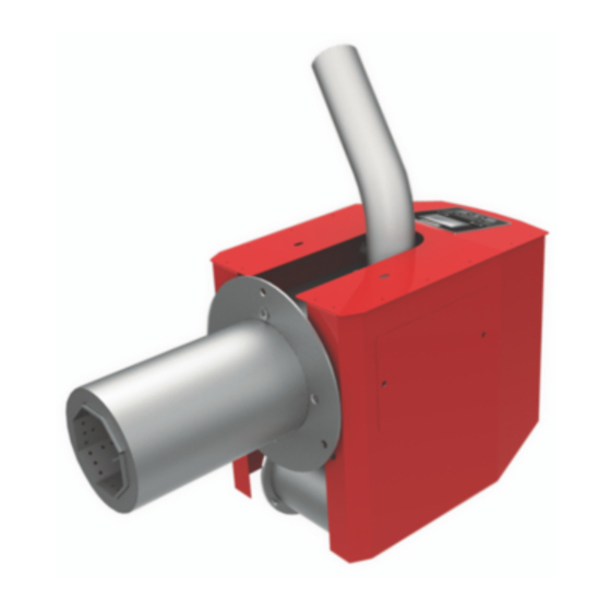
INSTALLATION and OPERATION MANUAL INSTALLATION and OPERATION MANUAL Table 1. Combustibility of external tube with sheet metal mantle. PPPconstruction materials Longitudinally, under the housing, there are blow chamber, fuel ignition heater, Stone, bricks, ceramic Class А - tiles, baked clay, fan and power supply. On the upper part non- solutions, plaster free of of the burner there is a feeder chute... -
Page 8: Fuel
INSTALLATION and OPERATION MANUAL INSTALLATION and OPERATION MANUAL • B uilt-in controller. current, etc.), the overload is borne by The main control unit, located in the the electrical fuse fitted on the main burner, manages the entire heating control panel of the burner (10 А). process. - Page 9 INSTALLATION and OPERATION MANUAL INSTALLATION and OPERATION MANUAL Better control of fuel quantity. The small consistently low moister content of size of the pellets allows for precise fuel pellets (consistently under 10% as feeding. On the other hand, the supply opposed to 20% to 60% moisture content of air for reaching optimal combustion of the logs).
-
Page 10: Transportation Of The Pellet Burner
INSTALLATION and OPERATION MANUAL INSTALLATION and OPERATION MANUAL following the instructions on the label - When purchasing pellets, ask to be protected from adverse weather for conformity declaration conditions (snow, rain and dust) from and certificate issued by an the shocks, and other activities likely to accredited laboratory and... -
Page 11: Storage Of The Pellet Burner
INSTALLATION and OPERATION MANUAL INSTALLATION and OPERATION MANUAL Recommended relative humidity -below 70%. When stored, the devices shall not have direct contact with the ground, placed on pallets, maximum two tiers and in their original packaging. The storage period is not more than 2 years from date of manufacture. - Page 12 INSTALLATION and OPERATION MANUAL INSTALLATION and OPERATION MANUAL 7.2. Connecting the pellet burner to the Pell Pell Pell Pell Pell mains power supply А 250 Such connection must be performed by a technician / B 390 service shop authorized for such C 250 operations. 7.1. Pellet burner connection to the fuel Caution! ELECTRIC SHOCK hopper and pellet auger HAZARD! - Before opening the unit: switch Take the feeder chute flexible hose (from off the voltage and secure the...
- Page 13 INSTALLATION and OPERATION MANUAL INSTALLATION and OPERATION MANUAL Table 3. OUPUTS of NPBC-V3C-1/NPBC-V4C-1/NPBC-V4E-1 OUTPUTS INPUTS Air fan Room thermostat. A normally open or normally closed contact can be connected to this input without additional voltage! Flue gas fan Photosensor The pin is not output for binding! Fuel auger Temperature sensor at the top of the buffer...
- Page 14 INSTALLATION and OPERATION MANUAL INSTALLATION and OPERATION MANUAL Diagram 6. Electrical diagram of connecting the internal devices / sensors to the controller...
- Page 15 INSTALLATION and OPERATION MANUAL INSTALLATION and OPERATION MANUAL 7.3. Trouble - shooting Table 4. Fault Cause Solution 1. Low temperature in 1.1. Immediately consult your the boiler on which 1.1. Inadequate sizing and/ installer about the problem. the burner is installed. or combination of heating Mount the supplied filling and Unable reach...
-
Page 16: Burner Operating
INSTALLATION and OPERATION MANUAL INSTALLATION and OPERATION MANUAL 8. BURNER OPERATING 8.4. Installer prescriptions regarding burner servicing and maintenance 8.1. Ignition. Before the heating season it is mandatory After the start up of the burner from to check up and clean the burner and its the control panel, the main pellet auger components. - Page 17 INSTALLATION and OPERATION MANUAL INSTALLATION and OPERATION MANUAL Type of Procedure Duty of: maintenance Cleaning of combustion chamber by poker and scraper Weekly User brush Dismantling of combustion chamber housing (A). Cleaning of combustion chamber by scraper brush and User / Monthly vacuum cleaner.
-
Page 18: Microprocessor Control
INSTALLATION and OPERATION MANUAL INSTALLATION and OPERATION MANUAL 9. MICROPROCESSOR CONTROL 9.1. View of the controller. Explanation The NPBC-V4 controller must be powered for at least 3 minutes of the buttons and indicators for the clock maintenance and The NPBC-V4C-1 controller is controlled fuel monitoring system to work via its "Control Module" using 6 buttons. properly when the power is off! The functions of each button are shown below:... - Page 19 INSTALLATION and OPERATION MANUAL INSTALLATION and OPERATION MANUAL 9.2. LCD Screen. Explanation of the display indication: After turning on the power, the controller displays its main screen, which has the following view: Ribbon with icons for the status of the outputs and Inter- Clock net connecti on Informati on fi...
- Page 20 INSTALLATION and OPERATION MANUAL INSTALLATION and OPERATION MANUAL Explanation of the display indication: 9.3. Controller operation: The burner operated by NPBC-V4C-1 can operate in both continuous mode and Illuminance level measured by the timer mode. When in timer mode, the photosensor. burner operates only at user-specified intervals of the day and days of the Chimney fan speed.
- Page 21 INSTALLATION and OPERATION MANUAL INSTALLATION and OPERATION MANUAL The burner then goes into the ignition is made to ignite. In order not to clog the burner with unburned pellets, the phase. amount of new pellets fed is halved with The burner ignition procedure begins each subsequent ignition attempt.
- Page 22 INSTALLATION and OPERATION MANUAL INSTALLATION and OPERATION MANUAL capacities are used during normal not the heater. operation of the burner to heat the boiler. The fourth power is to maintain The burner is cleaned by increasing to the fire when it is not necessary to heat 100% the speed of the main fan and the water in the boiler and thus avoids if an additional powerful fan or other...
- Page 23 INSTALLATION and OPERATION MANUAL INSTALLATION and OPERATION MANUAL ignited automatically. With the On / Off button goes to the The controller uses another method of mode selection menu. intermediate cleaning, in which the fire is not extinguished, but only increases Use the or buttons to highlight the power of the fan or triggers the FC...
- Page 24 INSTALLATION and OPERATION MANUAL INSTALLATION and OPERATION MANUAL remaining heat energy of the water in 9.4.2. Change the set temperature for the boiler will be used. heating the water in the boiler. When the burner is switched on, the By pressing the buttons "Fuel number" field will appear first. , when the controller is in the "Main If all conditions for ignition of the screen", you switch to the screen for...
- Page 25 INSTALLATION and OPERATION MANUAL INSTALLATION and OPERATION MANUAL pellets during the day. By pressing and holding the Menu button for more than 2 seconds, the readings Consumption of pellets for the total consumption of pellets are kg Thu 28/04/21 reset. In addition, remember the date and time of this reset, thanks to which you will have information for what period the next "Total cost"...
- Page 26 INSTALLATION and OPERATION MANUAL INSTALLATION and OPERATION MANUAL WiFi network to connect to it 9.4.8. Diagnosis • AP Associated - The modem has By pressing the button , when the connected to the router controller is in the "Information" screen, • Internet Access - Has an Internet you go to the "Diagnostics"...
- Page 27 INSTALLATION and OPERATION MANUAL INSTALLATION and OPERATION MANUAL Table 5. Message Clear Description грешка Reverse combustion button A reverse combustion thermostat has tripped Interrupted TS boiler automatically Interrupted boiler thermal sensor Short in TS boiler automatically Short in the boiler thermal sensor Frozen boiler button Time and date of registration of the damage...
-
Page 28: Adjustments Of Operating Parameters
INSTALLATION and OPERATION MANUAL INSTALLATION and OPERATION MANUAL 10. ADJUSTMENTS OF OPERATING / unselected) or a list of text values. Pa- PARAMETERS rameter fields are some of the following types: numeric parameters, selection 10.1. Ways to change the operating fields with possible values activated / not parameters activated (selected / unselected) or a list When the parameters required for the... - Page 29 INSTALLATION and OPERATION MANUAL INSTALLATION and OPERATION MANUAL Pump control - sets the operating mode verification of the above parameters. of the pumps of the external heating sys- Language - Change the language. tems, as well as their on and off tempera- Timers - Setting and activating time inter- tures.
- Page 30 INSTALLATION and OPERATION MANUAL INSTALLATION and OPERATION MANUAL The fire will be considered lit if the pho- are intended, and therefore you must first go through the choice of one of the tosensor measures a level above 100 for fuels. more than 20 seconds.
- Page 31 INSTALLATION and OPERATION MANUAL INSTALLATION and OPERATION MANUAL and go to the front screen. main and chimney, as well as the dura- tion (Duration [sec]) of the burning pe- 10.3.2. Fuel-dependent service settings. riod of the first dose. No new pellets are fed during the first dose incineration. To enter these settings, you need to en- In the lower field, the retention time ter the main screen for service settings...
- Page 32 INSTALLATION and OPERATION MANUAL INSTALLATION and OPERATION MANUAL which is the time between two fuel sup- average power can be reduced to the fol- ply periods, are set. In order for the fire lowing (100 + 50) / 2 = 75. The switch- to burn properly, an appropriate amount ing time will depend on the inertia of of air must be supplied.
- Page 33 INSTALLATION and OPERATION MANUAL INSTALLATION and OPERATION MANUAL When adjusting the maximum burner D1>Intermediate cleaning temperature, information is displayed to adjust the buffer temperature. Activation Cycle (min) Duration (sec) Fan change Temperature Buffer Basic Fan Chimney Fan EXIT FC 10.4. Activation of buffer vessel man- agement.
- Page 34 INSTALLATION and OPERATION MANUAL INSTALLATION and OPERATION MANUAL Range of adjustable parameters Default Menu Parameters Unit Pell Pell Pell Pell Pell Pell Display Brightness level Heating С Pump Pump Hysteresis С control DHW pump DHW temp. С Hysteresis С Auger Work Basic burner Additionally settings Maximum temperature...
- Page 35 INSTALLATION and OPERATION MANUAL INSTALLATION and OPERATION MANUAL Range of adjustable parameters Default Menu Parameters Unit Pell Pell Pell Pell Pell Pell Duration speed Kindling Chimney Fan speed Р1 Р2 Portion 25.0 Cycle Power Р1 speed Chimney Fan speed Portion 25.0 Cycle Power Р2 speed Chimney Fan speed...
-
Page 36: Technical Features
INSTALLATION and OPERATION MANUAL INSTALLATION and OPERATION MANUAL 11. TECHNICAL FEATURES OF PELLET BURNER PELL 11.1. Elements of pellet burner PELL Diagram 8. Elements of pellet burner Pell 1. Pellet burner Pell 6. Feeder chute 2. Auger flexible pipe connection 7. Burner housing 3. Auger` motor 8. - Page 37 INSTALLATION and OPERATION MANUAL INSTALLATION and OPERATION MANUAL 11.3. Technical parameters Table 7 Pell 25 Pell 40 Pell 70 Pell 90 Pell 150 Nominal heat output Min./Max. heat output 5÷25 10÷40 15÷70 30÷90 50÷150 Average Firing-Up mode ~ 400 ~ 400 ~ 400 ~ 400 ~ 400 power...
-
Page 38: Recycling
INSTALLATION and OPERATION MANUAL INSTALLATION and OPERATION MANUAL 12. RECYCLING AND WASTE DISPOSAL Submit all packaging material for recycling according to the local regulations and requirements. and environment. Both metal and non-metal parts are sold out to licensed organizations At the end of life cycle of each product its for recyclable metal or non-metal waste components are due to be disposed of in collection. - Page 39 INSTALLATION and OPERATION MANUAL INSTALLATION and OPERATION MANUAL...
- Page 40 tel.: +359 700 17 343 www.burnit.bg...
Need help?
Do you have a question about the BURNIT Pell Series and is the answer not in the manual?
Questions and answers