
Related Manuals for Kaysun KCCHT-02


Summary of Contents for Kaysun KCCHT-02
- Page 1 OWNER’S MANUAL Central Heat Pump Heater Wire Controller KCCHT-02 IMPORTANT NOTE: Thank you for purchasing our product. Before using your unit, please read this manual carefully and keep it for future reference.
- Page 2 • This manual gives detailed description of the precautions that should be brought to your attention during operation. • In order to ensure correct service of the wired controller please read this manual carefully before using the unit. • For convenience of future reference, keep this manual after reading it.
-
Page 3: Table Of Contents
ÍNDEX 1. Safety precautions ................1 2. Overview of wire controller ..............3 3. Whole instruction of wire controller..........4 4. Operation instruction ...............6 5. Error alarm handling...............14 ATTACHED PICTURE (I) ..............15... -
Page 4: Safety Precautions
1. Safety precautions The following contents are stated on the product and the operationmanual, includ- ing usage, precautions against personal harm and property loss, and the methods of using the product correctly and safely. After fully understanding the following contents (identifiers and icons), read the text body and observe the following rules. ■... - Page 5 WARNING • Please entrust the distributor or professionals to install the unit. • Imporper installation may lead to electric shock or fire. CAUTION • For protecting the device, do not repeatedly or quickly shift modes. Each wire controller operation to off the unit, it must be waited for 3 minutes or waited for all the units stopped then can re-operate the wire controller to start the outdoor unit.
-
Page 6: Overview Of Wire Controller
Overview of wired controller Basic conditions of operating the wired controller. Applicable range of supply voltage:Input voltage is 10V AC. Operating environment temperature of wired controller: -10°C~+43°C. Operating RH of wired controller: RH 40%~RH90%. Main functions of this wire controller as follows: Touch key operation;... -
Page 7: Whole Instruction Of Wire Controller
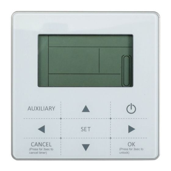
3. Whole instruction of wire controller Operation icon Water temp. Mode area ON/OFF Key Setting temperature Right, Left Right Key Timing On/Off OK key Function Icon Setting key On-line Unit Qty. Indication Add, Reduce key Reserved Cancel key Clock Reserved. key... - Page 8 1. Operation icon : Indicate the ON and OFF status; when it is ON, it will display; when it is OFF, it will disappear; 2. Mode area: Indicate the main unit operating mode; details refer to Page 15; 3. Setting temperature: 2 status can be displayed: 4.
-
Page 9: Operation Instruction
Operation instruction 4.1. On and Off the main unit 1. Press the On/Off key to control On and Off status of the main unit. 2. Under Off status, press the On/Off key “ ” to operate the main unit, at that time the LCD of wire controller will display the operation icon “... - Page 10 Fig.4-2 2) Timing setting: can set 3 timing periods on the wire controller: Timer 1, Timer 2, Timer 3, and then control the main unit to ON and OFF in different periods. Setting method: press “Setting” key under main page twice to enter timing setting.
- Page 11 This time the hour of the clock will flash, it means the current setting is the hour of Timer 1 “Off”, press the “▲” or “▼” to adjust, press “ ” key when finished, and then the minute of the clock will flash, it means the current setting is the minute of Timing 1 “Off”, press the “▲”...
- Page 12 During any period of timing setting to press “OK” key , then the timing period has been set will be effective (only when the “On” and “Off” of one timing period have been set then this period setting can be finished). Press “Cancel”...
- Page 13 4) Set clock Fig.4-9 This time the hour of the clock will flash, it means the current setting is the hour of the clock, press the “▲” or “▼” to adjust, press “ ” key when finished, and then the minute of the clock will flash, it means the current setting is the minute of the clock, press the “▲”...
- Page 14 Fig.4-10 2) ADDRESS setting function The address of wire controller can be set by pressing this button. The address range 0~15, therefore, 16 wire controller could be parallel at most. Operation method: Press “AUXILIARY” “►” two button for 3 seconds to enter the wired remote address selection.
- Page 15 Fig.4-12 Check 1) Check function allows the user to query all the operating parameters and error and protection information of the main unit. 2) Enter method: long press “Set” key for 3 seconds to enter check interface, as the figure display: Fig.4-13 3) Press the “▲”...
- Page 16 Table 4-1 outlet water temperature Tou->2 inlet water temperature T in-> outdoor ambient temperatures T4->4 outdoor pipe temperature T3A-> outdoor pipe temperature T3B->6 current of the compressor IA-> current of the compressor Ib->8 anti-frozen temperature T6-> electronic expansion valv opening FA->10 electronic expansion valv opening Fb-> Last one error or protection->12 Last second error or protection->...
-
Page 17: Error Alarm Handling
5. Error handling When the unit has error or protection, “ ” icon will be flashed. Long press “Setting” for 3 seconds to enter spot check, and then press the “▲” or “▼” key to query the unit of 0-15#, if the error icon was on during query, that means the corresponding outdoor unit has error or protection at that time, and then can spot check the last 1, 2, 3 times error or protection of this outdoor unit. -
Page 18: Attached Picture (I)
ATTACHED PICTURE (I) INSTALLATION PROCEDURE Installation procedure: Outdoor unit Outdoor unit Outdoor unit Outdoor unit Wire Controller Wire Controller Wire Controller Wire Controller Use PQE connect with each other when several wire-controllers are parallel. The wiring procedure and principles are shown in the figure: Adapter Wire Controller Yellow... - Page 19 MD13U-005FW 202055100959...
Need help?
Do you have a question about the KCCHT-02 and is the answer not in the manual?
Questions and answers