
Related Manuals for Kaysun KC-03 SPS


Summary of Contents for Kaysun KC-03 SPS
- Page 1 INSTALLATION AND OWNER’S MANUAL WIRED REMOTE CONTROLLER MODEL: KC-03 SPS IMPORTANT NOTE: Read this manual carefully before installing or operating your wired remote controller. Make sure to save this manual for future reference.
- Page 3 • This manual gives detailed description of precautions that should be brought to your attention during operation. • In order to ensure correct service of the wired controller please read this manual carefully before using the unit. • For convenience of future reference, keep this manual after reading it.
-
Page 4: Table Of Contents
CONTENTS 1. SAFETY PRECAUTION................1 2. INSTALLATION ACCESSORY..............2 3. INSTALLATION METHOD................4 4. SPECIFICATION..................9 5. FEATURE AND FUNCTION OF THE WIRED CONTROLLER....10 6. NAME ON THE LCD OF THE WIRE CONTROLLER........ 11 7. NAME OF BUTTON ON THE WIRE CONTROLLER........ 12 8. -
Page 5: Safety Precaution
1. SAFETY PRECAUTION • Read the safety precautions carefully before installing the unit. • Stated below are important safety issues that must be obeyed. Means improper handling may lead to personal death or severe injury. WARNING CAUTION Means improper handling may lead to personal injury or property loss. -
Page 6: Installation Accessory
2. INSTALLATION ACCESSORY Select the installation location Don’t install at the place where cover with heavy oil, vapor or sulfureted gas, otherwise, this product would be deformed that would lead to system malfunction. Preparation before installation 1. Please confirm that all the following parts you have been supplied. No. - Page 7 2. INSTALLATION ACCESSORY Precaution of install the wire controller 1. This manual provides the installation method of wire controller. Please refer to the wiring diagram of this installation manual to wire the wire controller with indoor unit 2. The wire controller working in low voltage loop circuit. Forbid to directly contact the cable of 220Vcommercial electricity or of 380V high voltage, and don’t wire this kind of wire in the said loop;...
- Page 8 3. INSTALLATION METHOD 1. Wired remote controller structure size figure Fig 3-1 2. Remove the upper part of wire controller • Insert a slot screwdriver into the slots in the lower part of the wire controller (2 places), and remove the upper part of the wire controller. (Fig. 3-2) NOTICE The PCB is mounted in the upper part of the wire controller.
-
Page 9: Installation Method
3. INSTALLATION METHOD 3. Fasten the black plate of the wire controller • For exposed mounting, fasten the back plate on the wall with the 3 screws (M4x20) and plugs. (Fig. 3-3) Back plate Screws (M4x20 Fig 3-3 • For flush-mounting, fasten the back plate on the switch box with 2 screws (M4x25) and fasten it on the wall with 1 screw (M4x20). - Page 10 3. INSTALLATION METHOD 4. Battery installation Fig 3-5 • Put the battery into the installation site and make sure the positive side of the battery is in accordance with the positive side of installation site. (See Fig. 3-5) • Please set the time corrected on the first time operation. Batteries in the wire controller can timing under power failure which ensure the time keep right.
- Page 11 3. INSTALLATION METHOD 5. Wire the indoor unit 4 methods 1 from the rear; 2 from the bottom; 3 from the top; 4 from the top center. 1 indoor unit 2 notch the part for the wiring to pass through with nippers, etc. Connect the terminals to the remote controller (HA, HB), and the terminals of the indoor unit (HA, HB).
- Page 12 3. INSTALLATION METHOD NOTE: DO NOT allow water to enter the remote control. Use the trap and putty to seal the wires. Putty Trap Putty Putty Trap Trap Fig 3-6 6. Reatrach the upper case and then buckle tht upper case; avoid clamping the wiring du- ring installation.
-
Page 13: Specification
4. SPECIFICATION Input voltage DC 5V/DC 12V Ambient temperature -5~43ºCn(23~110ºF) Ambient humidity RH40%~RH90% Wiring specifications Wiring type Size Total length Shielded vinyl cord 0.75-1.25mm² ≤50m (164’) or cable... -
Page 14: Feature And Function Of The Wired Controller
5. FEATURE AND FUNCTION OF THE WIRED CONTROLLER Feature: LCD display. Malfunction code display: it can display the error code, helpful for service. 4-way wire layout design, no raised part at backside, more convenient to place the wires and install the device. Room temperature display. -
Page 15: Name On The Lcd Of The Wire Controller
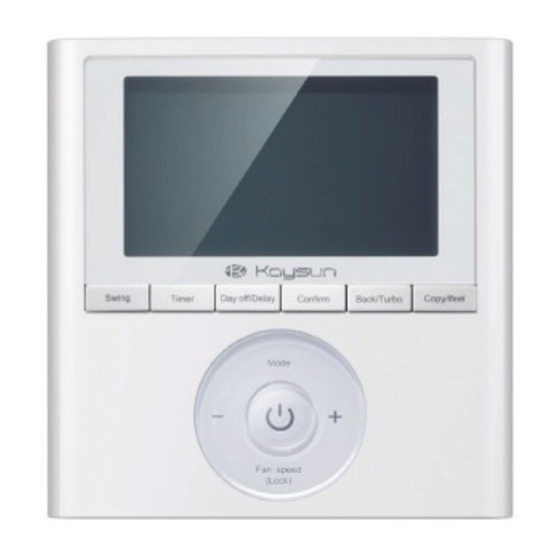
6. NAME ON THE LCD OF THE WIRE COTROLER Operation mode indication Fan speed indication Left-right swing indication Up-down swing indication Faceplate function indication Main unit and secondary unit indication Ifeel function indication Turbo function indication ºC / ºF indication Temperature display Lock indication Room temperature indication... - Page 16 7. NAME OF THE BUTTON ON THE WIRE CONTOLER MODE button POWER button Adjust button FAN SPEED button SWING button TIMER button DAY OFF/DEL button COPY/FOLLOW ME button BACK/TURBO button CONFIRM button...
-
Page 17: Preparatory Operation
8. PREPARATORY OPERATION Set the current day and time Press the Timer button for 3 seconds or more. The timer display will flash. Press the button “+” or “-” to set the date. The selected date will flash. The date setting is finished and the time setting is prepared after pressing Timer button or there is no pressing button in 10 se conds. - Page 18 9. OPERATION To start/stop operation Press the Power button. To set the operation mode Operation mode setting Press the Mode button to set the operation mode. (Heat function is invalid for cool only type unit) Room temperature setting Press the button “+” or “-” to set the room temperature. Indoor Setting Temperature Range: 17~30ºC (62~86 ºF/62~88 ºF (Depending on mo dels)).
- Page 19 9. OPERATION Fan speed setting Press the Fan speed button to set the fan speed. (This button is unvailable when in the mode of Auto or Dry) Room temperature sensor selection Press the Follow me button to select whethe the room temperature is detec ted at the indoor unit or the wire controller.
- Page 20 9. OPERATION Child lock function Keypad tone setting ºC & ºF scale selection (on some models) Press the lock button for 3 seconds to activate the child lock function and lock all buttons on the wire controller. Press the button again for 3 seconds to deactivate the child lock function. When the child lock function is activated, the mark appears.
-
Page 21: Operation
9. OPERATION Turbo function (on some models) Press the turbo button to activate the turbo function. Press the button again to deactivate the turbo function. When the turbo function is activated, the mark appears. Faceplate function (on some models) 1. When the unit is off, press the Mode button long to activate the faceplate function. - Page 22 9. OPERATION Swing function (For the unit left & right auto swing models only) 1 Up-Down swing Press the Swing button to start up-down swing function. Press it again to stop. Whe the Up-Down swing function is activated, the mark appears. 2.
- Page 23 9. OPERATION Swing function (For the unit without left & right auto swing function models) Up-Down airflow direction and swing • Use Swing button to adjust the Up-down airflow direction. 1. Press the button every time, the louver swings 6 degrees. 2.
-
Page 24: Timer Functions
10. TIMER FUNCTIONS WEEKLY timer Use this timer function to set operating times for each day of the week. On timer Use this timer function to start air conditioner operation. The timer opera tes and air conditioner operation starts after the time has passed. Off timer Use this timer function to stop air conditioner operation. - Page 25 10. TIMER FUNCTIONS To set the On or Off TIMER Press the Timer button to select the Press the confirm button and Clock display is flashing. ex. Off timer set at PM 6:00 Press the button “+” or “-” to set the time. After the time is set, the timer will start or stop automatically.
- Page 26 10. TIMER FUNCTIONS To set the On or Off TIMER Press the Timer button to select the Press the Confirm button and Clock display is flashing. Press the button “+” or “-” to set the time of On timer, and then press the Confirm button to confirm the setting.
- Page 27 11. WEEKLY TIMER To set the On or Off TIMER Weekly timer setting Press the Timer button to select the and then press the Confirm button to confirm. Day of the week setting Press the button “+” or “-” to select the day of the week and then press the Confirm button to confirm the setting.
- Page 28 11. WEEKLY TIMER Up to 4 timer settings can be saved for each day of the week. It is conventent if the WEEKLY TIMER is set according to the user’s life style. Off timer setting of timer setting 1 Press the button “+” or “-” to set the time of Off ti and then press the Confirm button to con firm the setting.
- Page 29 11. WEEKLY TIMER WEEKLY timer operation To activate WEEKLY TIMER operation Press the Timer button while is displayed on the LCD. To deactivate WEEKLY TIMER operation Press the Timer button while is disappear from the LCD. • To turn off the air conditioner during the weekly timer 1.
- Page 30 11. WEEKLY TIMER To set the DAY OFF (for a holiday) During the weekly timer, press the Confirm button. Press the button “+” or “-” to select the day in this week. Press the Day off button to set the DAY OFF. mark is hidden ex.
- Page 31 11. WEEKLY TIMER DELAY function During the weekly timer, pressing the Del button once, display “ “. Press this button twice, display “ “ and wait 3 seconds to confirm. It means the unit will override 1 hours; Press this button three times, display “ “...
- Page 32 11. WEEKLY TIMER Press the Copy button, the letter “CY” will be shown on the LCD. Press the button “+” or “-” to select the day to copy to. Press the Copy button to confirm. mark flashes quickly ex. Copy the setting of Monday to Wednesday Other days can be copied by repeating step 4 and 5.
-
Page 33: Fault Alarm Handing
12. FAULT ALARM HANDING If the system does not properly operate except the above mentioned cases or the above men- tioned malfunctions is evident, investigate the system according to the following procedures. MALFUNCTION & PROTECTION DEFINE DISPLAY DIGITAL TUBE Error of communication between wire con- troler and indoor unit. - Page 34 QSXUI-010AEN 16117100A03215 20170727...
- Page 35 The design and specifications are subject to change without prior noti- ce for product improvement. Consult with the sales agency or manufac- turer for details.