Table of Contents
Advertisement
Quick Links
AVR1014: MC303 Hardware User Guide
Features
• Motor Control device board for Atmel
• Modular system with 2.54mm pin header connector for power board MC300
• Sensor & sensorless modes capabilities
• Hall sensor header, Potentiometer for motor control
• Headers for Atmel DB101 Display module
• USB interface for PC connection and usage of Atmel Motor Control Center software
• ISP & debug interface for both ATxmega128A1 & USB device.
• Electric specifications:
- Supplied with Power board MC300 from 3.3V up to 5V
• Dimension: 100x100mm
1 Introduction
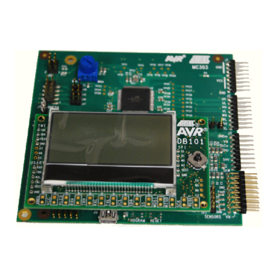
The MC303 is the device board for ATxmega128A1 AVR
can be connected to the general-purpose power stage board MC300 for driving
brushless DC, brushed DC and stepper motors. This board is also designed to be
connected on any other driver board which could share the same interface. Power
and all signals needed for a power stage board are available on the right side of
the board. Jumpers allow demonstrating sensor or sensorless modes of motor
control. Finally, interfaces like USB or Atmel DB101 Display module is also
available.
Figure 1-1. MC303 Motor control ATxmega128A1 processor board.
®
ATxmega128A1
®
microcontroller which
8-bit
Microcontrollers
Application Note
Rev. 8296A-AVR-03/10
Advertisement
Table of Contents

Related Manuals for Atmel AVR1014


Summary of Contents for Atmel AVR1014
- Page 1 • Hall sensor header, Potentiometer for motor control • Headers for Atmel DB101 Display module Application Note • USB interface for PC connection and usage of Atmel Motor Control Center software • ISP & debug interface for both ATxmega128A1 & USB device. • Electric specifications: - Supplied with Power board MC300 from 3.3V up to 5V...
-
Page 2: Hardware Overview
A Usart to USB bridge is available to transfer motor control status & commands to a PC software interface: Atmel Motor Control Center. Three 2.54mm headers are available to add the Atmel DB101 Display module in order to enhance visualization of motor control data & commands. -
Page 3: Pcb Layout
For individual component placement refer to the component floor plan. Figure 2-1. MC303 PCB layout. In Figure 2-1 the following areas are marked: 1. Power board connector. 2. USB bridge 3. Atmel DB101 Display module headers 4. Potentiometer for manual command 8296A-AVR-03/10... -
Page 4: Specifications
Figure 2-2. The device board interface on MC303 connector is split into four eight-pin connectors. Electric schematics and mechanical specifications are shown in Figure 2-3 and signal description in Table 2-1. AVR1014 8296A-AVR-03/10... - Page 5 AVR1014 Table 2-1. MC303 device board connector signal description. Located Name Direction Description J1p1 J1p2 System ground (Vin/VCC) J1p3 J1p4 Input Input power Vin (10-20V) J1p5 Input J1p6 Input Regulated power Vcc (3.3V/5V) J1p7 Input J1p8 System ground (Vin/VCC) J2p1...
- Page 6 Located Name Direction Description J4p14 Temp Input Temperature sensor input J4p15 J4p16 Spare Input/ Reserved Output Figure 2-3. Device board connector schematics. AVR1014 8296A-AVR-03/10...
- Page 7 Figure 2-4. USB Connection 2.3.3 DB101 Display module connectors The board has three 2.54 mm header to mount the Atmel DB101 Display module: J5, J7 & J9 (respectively UART, SPI, and TWI). The MC303 uses the UART. Figure 2-5. DB101 Display module...
- Page 8 The board has one JTAG/Debug connector, one populated for interfacing the ATxmega128A1 (J8), one not populated for the AT90USB1287 (USB bridge) (J12). Figure 2-7. ATxmega128A1 ISP/ JTAG header ISP/debugWire header for ATxmega128A1 ATxmega128A1 Note that J12 for AT90USB1287 is not mounted AVR1014 8296A-AVR-03/10...
- Page 9 AVR1014 2.4 Jumpers Refer to component floorplan for the location of the jumpers. Table 2-2. Jumpers and their function. Selects voltage source UVCC (Power supply for USB stage) When working at Vcc 2.7V-3.3V, the user can keep USB functional by selecting power supply for USB coming from VBUS rather than from Vcc.
- Page 10 Figure 2-9. J13: HALL sensors header J13: HALL sensor header AVR1014 8296A-AVR-03/10...
- Page 11 AVR1014 2.6 Schematics, component floorplan and bill of materials The schematics, component floorplan and bill of materials (BOM) for MC303 are found as separate PDF files distributed with this application note. They can be downloaded from http://www.atmel.com. 8296A-AVR-03/10...
-
Page 12: Detailed Description
ZC_W are connected to PH0, PH1 & PH2 of the ATxmega128A1. When using the filtered U, V, W signals coming from the MC300 power board, (U_Conditioned, V_ Conditioned, W_ Conditioned) & (U_cond_neg, V_cond_neg, W_cond_neg) are connected to (PA2, PA3, PA4) & (PA0, PA1, PA7) of the ATxmega128A1. AVR1014 8296A-AVR-03/10... - Page 13 (power supply of USB bridge) is properly configured. 3.3.2 Communication MC303 USB interface uses USB CDC class for communication. As the Atmel Motor Control Center software uses the RS232 interface, CDC class fits perfectly with the needs of this software. MC303 is delivered with a native USB CDC firmware in the AT90USB1287.
- Page 14 3.3.4 Atmel Motor Control Center The Atmel Motor Control Center used with the MC303 is available on the Atmel website: www.atmel.com. Figure 3-2. Motor Control Center User Interface. See Atmel Motor control center user’s guide & the application notes using MC303+MC300 &...
- Page 15 AVR1014 3.4 Interfacing MC303 with Atmel DB101 Display module The DB101 display module can be added to the MC303 (See application notes AVR481, AVR482, and AVR483 on www.atmel.com). 3.4.1 Connection DB101 connects using 3 headers J5, J6 & J7 (respectively UART, SPI, and TWI).
- Page 16 The list of jumpers J15, J16, J17 and J18 should be left open to activate the JTAG lines on the board: Table 3-1. JTAG enable jumpers Jumper JTAG Signal Figure 3-5. JTAG Jumpers JTAG Jumpers CAUTION: While updating the firmware, it is recommended to disconnect the motor on the MC300 power board. AVR1014 8296A-AVR-03/10...
- Page 17 BEEN ADVISED OF THE POSSIBILITY OF SUCH DAMAGES. Atmel makes no representations or warranties with respect to the accuracy or completeness of the contents of this document and reserves the right to make changes to specifications and product descriptions at any time without notice. Atmel does not make any commitment to update the information contained herein.
Need help?
Do you have a question about the AVR1014 and is the answer not in the manual?
Questions and answers