Table of Contents
Advertisement
Quick Links
Advertisement
Table of Contents

Related Manuals for CyberPower SM020KAMFA


Summary of Contents for CyberPower SM020KAMFA
- Page 1 SMART APP ONLINE MODULAR 3-PHASE UPS SYSTEM OPERATOR MANUAL SM020KAMFA SM040KAMFA SAVE THESE INSTRUCTIONS Please read this manual and follow the instructions for installation and operation. ©2021 Cyber Power Systems, Inc. All rights reserved.
-
Page 2: Table Of Contents
TABLE OF CONTENTS Table of Figures ................iii Table of Tables . - Page 3 TABLE OF CONTENTS 2.4 Procedure for Powering Down a UPS ..........26 2.5 EPO Procedure .
-
Page 4: Table Of Figures
TABLE OF FIGURES Fig 1-1: Single Unit Block Diagram ............6 Fig 1-2: Diagram of Connected Batteries . - Page 5 TABLE OF TABLES Table 1-1: System Options List ..............14 Table 1-2: UPS Cabinet Accessories .
-
Page 6: Safety Precautions
SAFETY PRECAUTIONS This manual contains information concerning the operation of CyberPower 3-phase online modular Uninterruptible Power Supply (UPS) systems. For safety reasons, this 3-phase UPS must be installed by a certified electrician licensed by the state, and following all local regulations and electrical codes. - Page 7 SAFETY PRECAUTIONS CONFORMITY AND STANDARDS This product complies with the following UPS product standards: * UL1778, safety requirements for UPS * FCC part 15, EMI requirements class A BACK-FEEDING PROTECTION This system has a control signal available for use with an externally located automatic device to protect against back-feeding voltage through the mains static bypass circuit.
- Page 8 SAFETY PRECAUTIONS NO USER-SERVICABLE COMPONENTS INSIDE All the equipment maintenance and servicing procedures involving internal access should be carried out only by trained personnel. The components that can only be accessed by opening the protective cover with tools cannot be maintained by user. This UPS fully complies with “IEC62040-1-1-General and safety requirements for use in operator access area UPS”.
- Page 9 Do not apply electrical power to the UPS equipment before the commissioning engineer arrives at installation site. The UPS should be installed by an authorized CyberPower engineer in order to retain the factory warranty. Any equipment not referred to in this manual is shipped with details of its own mechanical and electrical installation information.
-
Page 10: Chapter 1 - Introduction
CHAPTER 1 - INTRODUCTION 1.1 Introduction This modular UPS system utlizes an online double-conversion design and DSP-based digital control to supply stable, uninterrupted power for your critical loads. It eliminates damaging power surges and harmonic frequencies and regulates voltage to provide clean power to your devices. The key features of the modular UPS system are: •... -
Page 11: Fig 1-1: Single Unit Block Diagram
CHAPTER 1 - INTRODUCTION The 3-Phase UPS system provides the critical load (such as communication and data processing equipment) with high-quality, uninterruptible AC power. The power from the UPS is free from voltage and frequency variations and disturbances experienced at the mains AC input supply. This is achieved through high-frequency double-conversion. -
Page 12: Dual-Feed Input
CHAPTER 1 - INTRODUCTION 1.1.1 Dual-Feed Input Fig. 1-1 illustrates the 3-Phase UPS in what is known as the Dual-Feed configuration. In this configuration, the static bypass and maintenance bypass share the same independent bypass power supply and connect to the power supply through a separate switch. Where a separated power source is not available, the bypass and rectifier input supply connections are linked. -
Page 13: Parallel Ups Systems
CHAPTER 1 - INTRODUCTION 1.1.4 Parallel UPS Systems NOTICE Two UPS systems in a parallel system must have the same battery configuration. Each UPS system requires a separate battery cabinet. A parallel UPS system with multiple UPSs can be installed to provide a parallel capacity and/ or redundant system. -
Page 14: Fig 1-2: Diagram Of Connected Batteries
CHAPTER 1 - INTRODUCTION BCT6L9N225 • Contains four to six battery strings to be used with the SM-40kVA UPS. • Up to two external battery cabinets with a total of eight to twelve battery strings can be paralleled together to extend the run time. The 2nd battery cabinet is optional. NOTICE One battery string has two battery modules. -
Page 15: Operating Mode
CHAPTER 1 - INTRODUCTION 1.2 Operating Mode This 3-phase UPS is an online, double-conversion, reverse-transfer UPS that operates in these modes: • Normal mode • Battery Mode • Auto-restart mode • Bypass mode • Maintenance mode (manual bypass) • Parallel redundancy mode •... -
Page 16: Battery Mode
CHAPTER 1 - INTRODUCTION 1.2.2 Battery Mode Upon failure of the AC mains input power, the inverter power modules, which obtains power from the battery, supplies the critical AC load. There is no interruption in power to the critical load upon failure. -
Page 17: Bypass Mode
CHAPTER 1 - INTRODUCTION 1.2.4 Bypass Mode If the inverter overload capacity is exceeded when in normal mode, or if the inverter becomes unavailable, the static transfer switch will perform a transfer of the load from the inverter to the bypass source, with no interruption in power to the critical AC load. Should the inverter be asynchronous with the bypass, the static switch will perform a transfer of the load from the inverter to the bypass with power interruption to the load. -
Page 18: Parallel Redundancy Mode (System Expansion)
CHAPTER 1 - INTRODUCTION 1.2.6 Parallel Redundancy Mode (System Expansion) For higher capacity or higher reliability or both, the outputs of several 3-phase UPS systems can be programmed for direct parallel while a built-in parallel controller in each UPS system ensures automatic load sharing. -
Page 19: System Options And Accessories
3 layers (6 slots) for BM120V30ATY Battery Cabinet for SM040KAMFA: BCT6L9N225 6 layers (12 slots) for BM120V30ATY BM120V30ATY Battery Module w/8Ah 12VDC batteries 10pcs (120VDC) 100A Circuit Breaker for SM020KAMFA SMUCB100UAC input/output switching device 175A Circuit Breaker for SM040KAMFA SMUCB175UAC input/output switching device... -
Page 20: Accessories
CHAPTER 1 - INTRODUCTION 1.3.2 Accessories Table 1-2: UPS Cabinet Accessories Name 20kVA 40kVA Installation Manual Product Registration Card RMCARD205 RJ45/DB9 Serial Port RMCARD205 Quick Start Guide RMCARD205 Spare Jumper RMCARD205 Test Report Temperature Cable M4 Screw (accessory part) M6 Screw (accessory part) Ext. -
Page 21: Table 1-3: External Battery Cabinet Accessories
CHAPTER 1 - INTRODUCTION Table 1-3: External Battery Cabinet Accessories Name BCT3L8N125 BCT6L8N225 Product Registration Card M4 Screw (accessory part) M6 Screw (accessory part) Ext. Conn. Box (accessory part) Ext. Conn. Cover (accessory part) Rack Bracket Small x 2 Large x 2 (accessory part) Cable Ring Terminal Refer to Appendix B... -
Page 22: Chapter 2 - Operations And Start Up
CHAPTER 2 - OPERATIONS AND START UP HAZARDOUS MAINS VOLTAGE AND/OR BATTERY VOLTAGE PRESENT(S) BEHIND THE PROTECTIVE COVER The components that can only be accessed by opening the protective cover with tools cannot be serviced by user. Only qualified service personnel are authorized to remove such covers. -
Page 23: Introduction
CHAPTER 2 - OPERATIONS AND START UP 2.1 Introduction The 3-phase UPS system operates in the following three modes listed in Table.2-1. This section describes various kinds of operating procedures under each operating mode, including transfer between operating modes, UPS setting, and procedures for turning on/off inverter. Table 2-1: UPS Operating mode Operating mode Descriptions... -
Page 24: Fig 2-1: Sm-20Kva Ups Cabinet
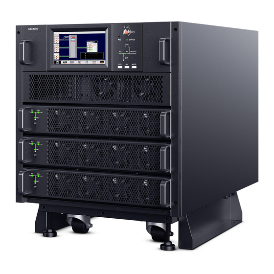
CHAPTER 2 - OPERATIONS AND START UP Touch screen LCD Dry Contact SNMP Parallel Perimeter metal strip Manual Bypass Bypass Module Power Module Front view Rear view Fig 2-1: SM-20kVA UPS Cabinet Touch screen LCD Dry Contact SNMP Parallel Manual Bypass Perimeter metal strip Bypass Module Power Module... -
Page 25: Fig 2-3: Bct3L9N125 Battery Cabinet
CHAPTER 2 - OPERATIONS AND START UP Perimeter metal strip Input Breaker Battery Module Battery Breaker Output Breaker Fig 2-3: BCT3L9N125 Battery Cabinet Perimeter metal strip Battery Module Input Breaker Battery Breaker Output Breaker Fig 2-4: BCT6L9N225 Battery Cabinet NOTICE The input and output breakers are optional. ©2021 Cyber Power Systems (USA), Inc. -
Page 26: Ups Start Up
CHAPTER 2 - OPERATIONS AND START UP 2.2 UPS Start Up Do not apply input power to the UPS until the installation is completed and the system has been commissioned by authorized personnel and the external power isolators are closed. NOTICE Before UPS start up, make sure the dry contact J4 pin1 and pin2 have been shorted. - Page 27 CHAPTER 2 - OPERATIONS AND START UP 2. Close external output circuit breaker. Close external mains input circuit breaker and connect the mains power. The LCD starts up at this time. The Rectifier indicator flashes during the startup of rectifier. The rectifier enters normal operation state, and after about 1 minute, the rectifier indicator goes steady green.
- Page 28 CHAPTER 2 - OPERATIONS AND START UP 4. Close external battery switch, battery indicator turn off, wait for a few minutes, the battery will be charged by UPS. The UPS Mimic LEDs will illuminate as following: Status Rectifier Indicator Green Battery Indicator Green Bypass Indicator...
-
Page 29: Procedures For Switching Between Operation Modes
CHAPTER 2 - OPERATIONS AND START UP 2.2.2 Procedures for Switching Between Operation Modes Switch from normal mode to bypass mode Press the button in the operate menu to switch to bypass mode. Note: In bypass mode, the load is directly fed by the mains power instead of the pure AC power from the inverter. -
Page 30: Procedure For Switching From Maintenance Mode To Normal Mode
CHAPTER 2 - OPERATIONS AND START UP (a) Single input (b) Dual Feed input Fig 2-5: External Maintenance Bypass WARNING If you need to service the module, wait for 10 minutes to let the DC bus capacitor fully discharge before removing corresponding module. When the manual bypass switch is in the on position, some parts of the UPS circuit still have hazardous voltage. -
Page 31: Procedure For Switching From Normal Mode To Manual Bypass Mode
CHAPTER 2 - OPERATIONS AND START UP 2.3.3 Procedure for Switching from Normal Mode to Manual Bypass Mode Reference Fig 2-5. Press the button in the operate menu on the LCD. The audible alarm will sound, the UPS Mimic indicator inverter will flash green and the Status indicator will turn a steady red. The load transfers to Static Bypass and the inverter is on standby. -
Page 32: Epo Procedure
CHAPTER 2 - OPERATIONS AND START UP 2.5 EPO Procedure The EPO button is designed to switch off the UPS in emergency conditions (e.g., fire, flood, etc.). To achieve this, just press and hold the EPO button, and the system will turn off the rectifier, inverter and stop powering the load immediately (including the inverter and bypass), and the battery stops charging or discharging. -
Page 33: How To Replace Power Module
CHAPTER 2 - OPERATIONS AND START UP 2.8 How to Replace Power Module The following procedures should only be performed by a certified technician. Maintenance guidance for power modules If the system is in normal mode, and the bypass is available and the redundant number of power module is at least 1: Go to operate menu and press the button to release shutdown power module function. -
Page 34: Changing The Current Date And Time
CHAPTER 2 - OPERATIONS AND START UP 2.10 Changing the Current Date and Time To change system date and time: In main menu, press the button to enter the function setting menu in the LCD screen. 2. Select date and time. 3. -
Page 35: Chapter 3 - Control And Display Panel
CHAPTER 3 - CONTROL AND DISPLAY PANEL This chapter introduces the functions and operation instructions of the UPS operator control and LCD display. 3.1 Introduction The operator control and display panel is located on the front panel of the UPS. Through the LCD panel, the operator can operate and control the UPS, and check all measured parameters, UPS and battery status, event and history logs. -
Page 36: Mimic Led
CHAPTER 3 - CONTROL AND DISPLAY PANEL 3.1.1 Mimic LED The LEDs shown on the mimic current path represent the various UPS power paths and show the current UPS operating status. The status description of indicators is shown in Table 3-2. Table 3-2: Status Description of Indicator Indicator State... -
Page 37: Audible Alarm (Buzzer)
CHAPTER 3 - CONTROL AND DISPLAY PANEL 3.1.2 Audible Alarm (buzzer) There are two different types of audible alarms during UPS operation. Table 3-3: Audible Alarms Alarm Purpose When system has general alarm (for example: main input abnormal), Two short, one long this audible alarm can be heard When system has serious faults (ex. -
Page 38: Fig 3-3: Menu Structure
CHAPTER 3 - CONTROL AND DISPLAY PANEL Table 3-5: LCD Icons Icon Description Return to main menu page Bypass, main, output (voltage, current, PF, frequency), battery information(capacity, remained time, worked days, battery temperature, ambient temperature), load information(percent, active load, reactive load, apparent load) Information of power module(main, output, load, S-code, module information) Date and time, language, communication, user (use user password 1), battery set, service set, rate set, configure... -
Page 39: Detailed Description Of Menu Items
CHAPTER 3 - CONTROL AND DISPLAY PANEL 3.3 Detailed Description of Menu Items UPS system information window UPS information window: unit model, module numbers, unit mode, current date and time are displayed. The information in the window is not necessary for the user to operate. Table 3-6: Description of Items in UPS System Information Window Display contents Definition... -
Page 40: Fig 3-5: Main Input And Output Information
CHAPTER 3 - CONTROL AND DISPLAY PANEL Submenu BYPASS, MAIN, OUTPUT Bypass information, main input and output information (voltage, current, frequency, PF) are displayed in cabinet menu, voltage is also shown in meter type. Current mimic status indicators, LCD and monitoring version are displayed. (a) Main input information (b) Output information Fig 3-5: Main Input and Output Information... -
Page 41: Fig 3-7: Power Module Information
CHAPTER 3 - CONTROL AND DISPLAY PANEL Enter the menu to get power module information Fig 3-7: Power Module Information NOTICE The 20kVA UPS can utilize up to 3 power modules and a 40kVA UPS can utilize up to 5 power modules. Module information menu includes: input, output, load, internal information, S-code, software version. -
Page 42: Fig 3-9: Module Information And S-Code
CHAPTER 3 - CONTROL AND DISPLAY PANEL Submenu INFO., S-Code INFO menu includes modules battery information, inlet temperature, outlet temperature, IGBT temperature. And S-code menu displays S-codes of power modules to help diagnose any faults that occur in the power modules. (a) Module information (b) S-code of the power module Fig 3-9: Module Information and S-code... -
Page 43: Table 3-7: Description Of Details Of Submenu In Setting
CHAPTER 3 - CONTROL AND DISPLAY PANEL Table 3-7: Description of Details of Submenu in Setting Submenu Name Contents Meaning Three formats: (a) year/month/day Date format setting (b) month/date/year Date & Time (c) date/month/year Time setting Set current time Current language Language in use Simplified Chinese, English, and Traditional Language... -
Page 44: Fig 3-11: System Operate
CHAPTER 3 - CONTROL AND DISPLAY PANEL Enter the menu to get history log of UPS system. Use to scroll the list. Enter the menu to control UPS system. The function and test command are shown as below: Fig 3-11: System Operate NOTICE The Reset Dust Filter Using Time is only applicable to units with the dust filter option. - Page 45 CHAPTER 3 - CONTROL AND DISPLAY PANEL Menu of Operations Functional operation Mute off or mute on. Fault clear manually Manually transfer to bypass or escape from bypass mode Transfer to inverter mode manually. The output could be interrupted. Enable the “OFF” button on the front panel of power module. Then the “OFF” button is available, user can press the button to shutdown the power module.
-
Page 46: Fig 3-12: Output And Bypass Waveforms
CHAPTER 3 - CONTROL AND DISPLAY PANEL Fig 3-12: Output and Bypass Waveforms ©2021 Cyber Power Systems (USA), Inc. All rights reserved. All other trademarks are the property of their respective owners. -
Page 47: Ups Event Log
CHAPTER 3 - CONTROL AND DISPLAY PANEL 3.4 UPS Event Log Table 3-8: UPS Events UPS events Description Fault Clear Manually clear fault Log Clear Manually clear History log Load On UPS Inverter feeds load Load On Bypass Bypass feeds load No Load No load Battery Boost... - Page 48 CHAPTER 3 - CONTROL AND DISPLAY PANEL UPS events Description This alarm is triggered by an inverter software routine when the amplitude or frequency of bypass voltage exceeds the limit. The alarm will automatically reset if the bypass voltage becomes normal.
- Page 49 CHAPTER 3 - CONTROL AND DISPLAY PANEL UPS events Description Output short Circuit. Fist check and confirm if loads have something wrong. Output Short Circuit Then check and confirm if there is something wrong with terminals, sockets or some other power distribution unit. If the fault is solved, press “Fault Clear”...
- Page 50 CHAPTER 3 - CONTROL AND DISPLAY PANEL UPS events Description The N# Power Module Output Over Load. This alarm appears when the load rises above 100% of nominal rating. The alarm automatically resets once the overload condition is removed. Check which phase has overload through the load (%) displayed in LCD so as to confirm if this alarm is true.
- Page 51 CHAPTER 3 - CONTROL AND DISPLAY PANEL UPS events Description Manual Transfer Byp Transfer to bypass manually Escape from “transfer to bypass manually” command. If UPS has Esc Manual Bypass been transferred to bypass manually, this command enable UPS to transfer to inverter.
- Page 52 CHAPTER 3 - CONTROL AND DISPLAY PANEL UPS events Description Rectifier CAN bus communication is abnormal. Please check if REC CAN Fail communication cables are not connected correctly. IO signals communication of inverter CAN bus is abnormal. Please INV IO CAN Fail check if communication cables are not connected correctly.
- Page 53 CHAPTER 3 - CONTROL AND DISPLAY PANEL UPS events Description While soft start procedures are finished, DC bus voltage is lower than the limitation of calculation according utility voltage. Please check Whether rectifier diodes are broken REC Soft Start Fail Whether PFC IGBTs are broken Whether PFC diodes are broken Whether drivers of SCR or IGBT are abnormal...
- Page 54 CHAPTER 3 - CONTROL AND DISPLAY PANEL UPS events Description Working life of capacitors is expired, and it’s recommended Capacitor Expired that the capacitors are replaced with new capacitors. It must be activated via software. Working life of power modules’ fans is expired, and it’s Fan Expired recommended that the fans are replaced with new fans.
-
Page 55: Chapter 4 - Snmp Card
CHAPTER 4 - SNMP CARD 4.1 Replace SNMP card SNMP card (RMCARD205) is installed on the back panel of bypass module in SM020KAMFA and SM040KAMFA. For detailed setting information, please refer to the RMCARD205 User Manual. To replace SNMP card: Remove the two screws of intelligent slot (see Fig. -
Page 56: Blank Pages For Notes
NOTES ©2021 Cyber Power Systems (USA), Inc. All rights reserved. All other trademarks are the property of their respective owners. - Page 57 NOTES ©2021 Cyber Power Systems (USA), Inc. All rights reserved. All other trademarks are the property of their respective owners.
Need help?
Do you have a question about the SM020KAMFA and is the answer not in the manual?
Questions and answers