Table of Contents
Advertisement
Quick Links
Advertisement
Table of Contents

Related Manuals for CyberPower SM020KAMFA


Summary of Contents for CyberPower SM020KAMFA
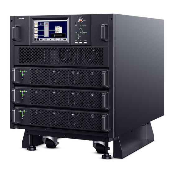
- Page 1 SMART APP ONLINE MODULAR 3-PHASE UPS SYSTEM INSTALLATION MANUAL SM020KAMFA SM040KAMFA SAVE THESE INSTRUCTIONS Please read this manual and follow the instructions for installation and operation. ©2021 Cyber Power Systems, Inc. All rights reserved.
-
Page 2: Table Of Contents
TABLE OF CONTENTS Table of Figures ................iii Table of Tables . - Page 3 TABLE OF CONTENTS 4.1.3 Frequency Converter Mode (option) ........69 4.1.4 Output System Connections .
-
Page 4: Table Of Figures
TABLE OF FIGURES Fig 1-1: SM-20kVA and SM-40kVA UPS Cabinets ..........5 Fig 1-2: BCT3L9N125 and BCT6L9N225 External Battery Cabinets. - Page 5 TABLE OF FIGURES Fig 3-12: Dual Feed with SM-20kVA Optional Configuration ........47 Fig 3-13: Dual Feed with SM-40kVA Optional Configuration .
- Page 6 TABLE OF FIGURES Fig 4-17: SM-20kVA UPS Dual-Feed Power Cable Entry ........68 Fig 4-18: SM-20kVA UPS Dual-Feed Power Wiring .
- Page 7 TABLE OF FIGURES Fig 4-49: Secure the Cable Gland and Conduit Plates of Battery Cabinet ..... . . 93 Fig 4-50: Secure the Neutral and Ground Cables ..........94 Fig 4-51: Secure the Input and Output Cables on UPS Cabinet .
- Page 8 Table 2-16: BCT6L9N225 Battery Cabinet Power Cable Connections Information ....30 Table 2-17: SM020KAMFA UPS Cabinet Power Cable Connections Size ......31 Table 2-18: SM040KAMFA UPS Cabinet Power Cable Connections Size .
-
Page 9: Safety Precautions
For safety reasons, this 3-phase UPS must be installed by a certified technician approved by CyberPower or an authorized representative of CyberPower. This is a Class C UPS system, and is designed exclusively for commercial or industrial use. It is not approved for use in a life-support capacity nor in a residential environment. - Page 10 SAFETY PRECAUTIONS BACK-FEEDING PROTECTION This system has a control signal available for use with an externally located automatic device to protect against back-feeding voltage through the mains Static Bypass circuit. If this protection is not used with the switchgear that is used to isolate the bypass circuit, a label must be added to the switchgear to advise service personnel that the circuit is connected to a UPS system.
- Page 11 SAFETY PRECAUTIONS SELF-SERVICE COMPONENTS All the equipment maintenance and servicing procedures involving internal access need special tools and should be carried out only by trained personnel. The components that can only be accessed by opening the protective cover with tools cannot be maintained by user.
- Page 12 SAFETY PRECAUTIONS INSTALLATION CAN ONLY BE DONE BY AUTHORIZED ENGINEERS Do not apply electrical power to the UPS equipment before the commissioning engineer arrives at installation site. The UPS should be installed by a qualified engineer in accordance with the information contained in this chapter. All the equipment not referred to in this manual is shipped with details of its own mechanical and electrical installation information.
-
Page 13: Chapter 1 - Introduction
CHAPTER 1 - INTRODUCTION 1.1 Installation Configurations Our CyberPower Smart App Online Three-Phase UPS systems are comprised of one or more UPS cabinets and battery cabinets depending on the required configuration. The 3-phase UPS cabinet and standard external battery cabinets are designed to be installed in side-by-side, tower-stacked or rack-mounted configurations. -
Page 14: Fig 1-2: Bct3L9N125 And Bct6L9N225 External Battery Cabinets
CHAPTER 1 - INTRODUCTION Fig 1-2: BCT3L9N125 and BCT6L9N225 External Battery Cabinets Fig 1-3: SM-20kVA UPS (1 unit) and BCT3L9N125 (2 units) ©2021 Cyber Power Systems (USA), Inc. All rights reserved. All other trademarks are the property of their respective owners. -
Page 15: Fig 1-4: Sm-40Kva Ups (1 Unit) And Bct6L9N225 (2 Units)
CHAPTER 1 - INTRODUCTION Fig 1-4: SM-40kVA UPS (1 unit) and BCT6L9N225 (2 units) Fig 1-5: SM-20kVA UPS Tower-stacked with BCT3L9N125 ©2021 Cyber Power Systems (USA), Inc. All rights reserved. All other trademarks are the property of their respective owners. -
Page 16: Fig 1-6: Sm-40Kva Ups Tower-Stacked With Bct6L9N225
CHAPTER 1 - INTRODUCTION Fig 1-6: SM-40kVA UPS Tower-stacked with BCT6L9N225 Fig 1-7: Rack-mount Installed with SM-20kVA UPS and BCT3L9N125 ©2021 Cyber Power Systems (USA), Inc. All rights reserved. All other trademarks are the property of their respective owners. -
Page 17: Fig 1-8: Rack-Mount Installed With Sm-40Kva Ups And Bct6L9N225
CHAPTER 1 - INTRODUCTION Fig 1-8: Rack-mount Installed with SM-40kVA UPS and BCT6L9N225 ©2021 Cyber Power Systems (USA), Inc. All rights reserved. All other trademarks are the property of their respective owners. -
Page 18: System Options And Accessories
SM040KAMFA UPS CABINET : 40KVA 40kW 208V 3-PHASE SM10KAPMA UPS POWER MODULE : 10KVA 10kW 208V 3-PHASE BATTERY CABINET for SM020KAMFA : 3 layers (6 slots) for BCT3L9N125 BM120V30ATY BATTERY CABINET for SM040KAMFA : 6 layers (12 slots) for BCT6L9N225... -
Page 19: Accessories
CHAPTER 1 - INTRODUCTION 1.2.2 Accessories Table 1-2: UPS Cabinet Accessories Name Installation Manual Product Registration Card RMCARD205 RJ45/DB9 Serial Port Connection Cable RMCARD205 Quick Start Guide RMCARD205 Spare Jumper RMCARD205 Test Report Temperature Cable M4 Screw (accessory part) M6 Screw (accessory part) Ext. -
Page 20: Table 1-3: External Battery Cabinet Accessories
CHAPTER 1 - INTRODUCTION Table 1-3: External Battery Cabinet Accessories Name BCT3L9N125 BCT6L9N225 Product Registration Card M4 Screw (accessory part) M6 Screw (accessory part) Ext. Conn. Box (accessory part) Ext. Conn. Cover (accessory part) Rack Bracket Small x 2 Large x 2 (accessory part) Cable Ring Terminal Detail List Refer to Appendix B... -
Page 21: Chapter 2 - Installation Plan And Unpacking
CHAPTER 2 - INSTALLATION PLAN AND UNPACKING Perform the following operations prior to installation: Visually inspect the UPS system cabinet and external battery cabinet for any damage that might have occurred in shipping. Report any damage to the shipper immediately. 2. -
Page 22: Table 2-1: Ups Cabinet Weight
Failure to follow guidelines may void your warranty. Table 2-1: UPS Cabinet Weight Weight kg(lbs) Shipping Model UPS Rating Power Modules Installed (w/o PMs) 10kVA 105.9(233) 77.1(170) SM020KAMFA 20kVA 105.9(233) 93.5(206) 20kVA(N+1) 105.9(233) 109.9(242) 10kVA 136.5(301) 97(214) 20kVA 136.5(301) 113.4(250) -
Page 23: Table 2-3: Ups Cabinet Clearances
CHAPTER 2 - INSTALLATION PLAN AND UNPACKING • The UPS cabinet uses forced cooling to regulate internal component temperature. • The external battery cabinet uses convection cooling to regulate internal component temperature. • Air inlets are in the front of the cabinet and outlets are in the back of the cabinet. •... -
Page 24: Fig 2-1: Sm-20Kva Ups Dimensions
CHAPTER 2 - INSTALLATION PLAN AND UNPACKING The floor mounting bracket can be mounted on the two sides of cabinet or mounted the front and back sides of cabinet. Fig 2-1: SM-20kVA UPS Dimensions Fig 2-2: SM-40kVA UPS Dimensions ©2021 Cyber Power Systems (USA), Inc. All rights reserved. All other trademarks are the property of their respective owners. -
Page 25: Fig 2-3: Bct3L9N125 Cabinet Dimensions
CHAPTER 2 - INSTALLATION PLAN AND UNPACKING Fig 2-3: BCT3L9N125 Cabinet Dimensions Fig 2-4: BCT6L9N225 Cabinet Dimensions ©2021 Cyber Power Systems (USA), Inc. All rights reserved. All other trademarks are the property of their respective owners. -
Page 26: Fig 2-5: Floor Mounting Bracket-Mounted The Sides Of Cabinet
CHAPTER 2 - INSTALLATION PLAN AND UNPACKING Fig 2-5: Floor Mounting Bracket-mounted the Sides of Cabinet Fig 2-6: UPS Cabinet Floor Mounting Dimensions for Side-mounted ©2021 Cyber Power Systems (USA), Inc. All rights reserved. All other trademarks are the property of their respective owners. -
Page 27: Fig 2-7: Floor Mounting Bracket-Mounted The Front And Back Of Cabinet
CHAPTER 2 - INSTALLATION PLAN AND UNPACKING Fig 2-7: Floor Mounting Bracket-mounted the Front and Back of Cabinet Fig 2-8: UPS Cabinet Floor Mounting Dimensions for Front- and Back-mounted ©2021 Cyber Power Systems (USA), Inc. All rights reserved. All other trademarks are the property of their respective owners. -
Page 28: Power Wiring Preparation
CHAPTER 2 - INSTALLATION PLAN AND UNPACKING 2.3 Power Wiring Preparation Design the cables according to the descriptions in this section, local regulatory wiring standards, and the environmental conditions. WARNING FAILURE TO FOLLOW ADEQUATE EARTHING PROCEDURES CAN RESULT IN EMI, ELECTRIC SHOCK HAZARD, OR RISK OF FIRE, SHOULD AN EARTH FAULT OCCUR. -
Page 29: Table 2-5: Maximum Steady State Ac And Dc Current
(kW) 208V 220V 208V 220V Battery/ Battery/ string string Table 2-6: SM040KAMFA and SM020KAMFA UPS Cabinet Power Cable Size Contents 10KVA 20KVA 30KVA 40KVA Cable Main Input Section (AWG) Cable Output Section (AWG) -
Page 30: Table 2-7: Bct3L9N125 And Bct6L9N225 Battery Cabinet Power Cable Size
CHAPTER 2 - INSTALLATION PLAN AND UNPACKING Table 2-7: BCT3L9N125 and BCT6L9N225 Battery Cabinet Power Cable Size Minimum Conductor Size AWG Model Connection 10kVA 20kVA Input Breaker 100A (Optional) Output Breaker BCT3L9N125 100A (Optional) Battery(+) Battery(N) Battery(-) Ground 10kVA 20kVA 30kVA 40kVA Input Breaker... -
Page 31: Table 2-8: Recommend Circuit Breaker Ratings
40KVA 175A 175A 175A 225A The power wiring connections for this UPS cabinet and external battery cabinet are rated at 90°C. Table 2-9: SM020KAMFA UPS Cabinet Cable Terminations Information Connection Bolt Type and Size Tool Size Torque UPS Cabinet Bolt... -
Page 32: Table 2-10: Sm040Kamfa Ups Cabinet Cable Connections Information
CHAPTER 2 - INSTALLATION PLAN AND UNPACKING Table 2-10: SM040KAMFA UPS Cabinet Cable Connections Information Connection Bolt Type and Size Tool Size Torque UPS Cabinet Bolt Bolt Size Size Bolt Shank Nm (lb in) Connections Head 1 Head 2 Head 1 Head 2 Phillips 13mm... -
Page 33: Table 2-11: Bct3L9N125 Battery Cabinet Cable Connections Information
CHAPTER 2 - INSTALLATION PLAN AND UNPACKING Table 2-11: BCT3L9N125 Battery Cabinet Cable Connections Information Connection Bolt Type and Size Tool Size Torque Battery Cabinet Bolt Bolt Size Size Bolt Shank Connections Head 1 Head 2 Head 1 Head 2 (lbs/in) 1/4-20 Phillips... -
Page 34: Table 2-12: Bct6L9N225 Battery Cabinet Cable Connections Information
CHAPTER 2 - INSTALLATION PLAN AND UNPACKING Table 2-12: BCT6L9N225 Battery Cabinet Cable Connections Information Connection Bolt Type and Size Tool Size Torque Battery Cabinet Bolt Bolt Size Size Bolt Shank Connections Head 1 Head 2 Head 1 Head 2 (lbs./in) Allen 13mm... -
Page 35: Table 2-13: Sm020Kamfa Ups Cabinet Power Cable Connections Information
CHAPTER 2 - INSTALLATION PLAN AND UNPACKING Table 2-13: SM020KAMFA UPS Cabinet Power Cable Connections Information Cable Cable Lug PN Lug PN CHAPTER 2 - INSTALLATION PLAN AND UNPACKING UPS Cabinet Connections 10kVA Lug # 20kVA Lug # RNBM5-6 RNBS22-6 INPUT (9Φ) -
Page 36: Table 2-14: Sm040Kamfa Ups Cabinet Power Cable Connections Information
CHAPTER 2 - INSTALLATION PLAN AND UNPACKING Table 2-14: SM040KAMFA UPS Cabinet Power Cable Connections Information 10kVA 20kVA 30kVA 40kVA UPS Cabinet Cable Cable Cable Cable Lug # Lug # Lug # Lug # Connections RNB5.5-8 RNB22-8 RNBS38-8 RNB60-8 INPUT (10Φ) (20Φ) (20Φ) -
Page 37: Table 2-15: Bct3L9N125 Battery Cabinet Power Cable Connections Information
CHAPTER 2 - INSTALLATION PLAN AND UNPACKING Table 2-15: BCT3L9N125 Battery Cabinet Power Cable Connections Information 10kVA 20kVA Cable Cable Battery Cabinet Connections Lug # Lug # BATTERY OUTPUT RNB14-8 RNBS38-8 (Battery Breaker) (14Φ) (14Φ) RNBM5-6 RNBS8-6 Chassis Ground (9Φ) (9Φ) UPS AC INPUT RNBM5-6... -
Page 38: Table 2-16: Bct6L9N225 Battery Cabinet Power Cable Connections Information
CHAPTER 2 - INSTALLATION PLAN AND UNPACKING Table 2-16: BCT6L9N225 Battery Cabinet Power Cable Connections Information 10kVA 20kVA 30kVA 40kVA Battery Cabinet Cable Cable Cable Cable Lug # Lug # Lug # Lug # Connections BATTERY RNB14-10 RNBS38-10 RNB70-10 RNB80-10 OUTPUT (Battery (11Φ) -
Page 39: Table 2-17: Sm020Kamfa Ups Cabinet Power Cable Connections Size
CHAPTER 2 - INSTALLATION PLAN AND UNPACKING Table 2-17: SM020KAMFA UPS Cabinet Power Cable Connections Size UPS Cabinet Connections AC INPUT 17mm 33.5mm 10.5mm 6.4mm BYPASS INPUT 17mm 33.5mm 10.5mm 6.4mm AC OUTPUT 17mm 33.5mm 10.5mm 6.4mm BATTERY INPUT 22mm 42.7mm... -
Page 40: Table 2-18: Sm040Kamfa Ups Cabinet Power Cable Connections Size
CHAPTER 2 - INSTALLATION PLAN AND UNPACKING Table 2-18: SM040KAMFA UPS Cabinet Power Cable Connections Size UPS Cabinet Connections AC INPUT 22mm 49.7mm 12mm 8.4mm BYPASS INPUT 22mm 49.7mm 12mm 8.4mm AC OUTPUT 22mm 49.7mm 12mm 8.4mm BATTERY INPUT 29mm 54.2mm 10.5mm Chassis Ground... -
Page 41: Table 2-19: Bct3L9N125 Battery Cabinet Power Cable Connections Size
CHAPTER 2 - INSTALLATION PLAN AND UNPACKING Table 2-19: BCT3L9N125 Battery Cabinet Power Cable Connections Size Battery Cabinet Connections BATTERY OUTPUT 25mm 42.7mm 9.5mm 8.4mm (Battery Breaker) Chassis Ground 17mm 29.2mm 6.4mm UPS AC INPUT (Input Breaker) 18mm 33.5mm 6.4mm (Option) Neutral Bus Bar 20mm... -
Page 42: Table 2-20: Bct6L9N225 Battery Cabinet Power Cable Connections Size
CHAPTER 2 - INSTALLATION PLAN AND UNPACKING Table 2-20: BCT6L9N225 Battery Cabinet Power Cable Connections Size Battery Cabinet Connections BATTERY OUTPUT 27mm 54.2mm 15mm 10.5mm (Battery Breaker) Chassis Ground 21mm 32.5mm 10mm 8.4mm UPS AC INPUT (Input Breaker) 22mm 49.7mm 13mm 8.4mm (Option) -
Page 43: Table 2-21: Recommended Crimping Tools
CHAPTER 2 - INSTALLATION PLAN AND UNPACKING Recommended Crimping Tool Cable lug manufacturer: K.S.T. Crimping tool manufacturer: Burndy - Hubbell Table 2-21: Recommended Crimping Tools Cable Size (AWG) Cable Lug Type Crimping Tool RNBM5-6, RNB5.5-8 Y8MRB-1 RNBS8-6, RNB8-8 Y8MRB-1 RNB14-8, RNB14-10 Y35, PAT750 UV6L RNBS22-6, RNB22-8... -
Page 44: Inspecting And Unpacking
CHAPTER 2 - INSTALLATION PLAN AND UNPACKING 2.4 Inspecting and Unpacking The UPS cabinets and battery cabinets are shipped bolted to a wooden pallet and covered with protective packaging material (see Fig 2-9). Fig 2-9: UPS and Battery Cabinets Shipped on Pallet WARNING The UPS and battery cabinets are heavy (see Table 2-1 and 2-2). -
Page 45: Fig 2-10: Remove The Wood Crates Of Ups Cabinets
NOTICE The SM040KAMFA and BCT6L9N225 retain the front wooden panel. The SM020KAMFA and BCT3L9N125 retain the top wooden panel. Fig 2-10: Remove the Wood Crates of UPS Cabinets... -
Page 46: Unloading The Ups And Battery Cabinets From The Pallet
NOTICE The SM040KAMFA and BCT6L9N225 used the front wooden panel. The SM020KAMFA and BCT3L9N125 used the top wooden panel. ©2021 Cyber Power Systems (USA), Inc. All rights reserved. All other trademarks are the property of their respective owners. -
Page 47: Fig 2-11: Front Wooden Panel Acts As A Ramp - Bct6L9N225
CHAPTER 2 - INSTALLATION PLAN AND UNPACKING 6. Use a Phillips screwdriver or a socket wrench (13mm) to remove bolts securing the left shipping bracket to the cabinet and use socket wrench (bottom, 16mm) and open wrench (up, 17mm) to remove two bolts securing the bracket to the pallet (see Fig 2-13). Remove the left shipping bracket. -
Page 48: Fig 2-13: Removing The Left Shipping Bracket - Bct6L9N225
CHAPTER 2 - INSTALLATION PLAN AND UNPACKING Fig 2-13: Removing the Left Shipping Bracket – BCT6L9N225 WARNING Do not stand directly in front of or behind the pallet while unloading the cabinet. If unloading instructions are not closely followed, the cabinet may cause serious injury. -
Page 49: Chapter 3 - Configurations And Wiring Diagrams
CHAPTER 3 - CONFIGURATIONS AND WIRING DIAGRAMS 3.1 UPS and Battery Cabinet Composition Touch screen LCD Dry Contact SNMP Parallel Perimeter metal strip Manual Bypass Bypass Module Power Module Front view Back view Fig.3-1: SM-20kVA UPS Cabinet Touch screen LCD Dry Contact SNMP Parallel... -
Page 50: Fig.3-3: Bct3L9N125 Battery Cabinet
CHAPTER 3 - CONFIGURATIONS AND WIRING DIAGRAMS Perimeter metal strip Input Breaker Battery Module Battery Breaker Output Breaker Fig.3-3: BCT3L9N125 Battery Cabinet Perimeter metal strip Battery Module Input Breaker Battery Breaker Output Breaker Fig.3-4: BCT6L9N225 Battery Cabinet NOTICE The input and output breakers are optional. ©2021 Cyber Power Systems (USA), Inc. -
Page 51: Fig 3-5: Diagram Of Battery Connections
CHAPTER 3 - CONFIGURATIONS AND WIRING DIAGRAMS Fig 3-5: Diagram of Battery Connections Table 3-1: UPS Cabinet Major Components Item Component Quantity Remarks System Display Requisite, factory installed Bypass module Requisite, factory installed Manual bypass breaker Requisite, factory installed Power module 1 ≤n ≤5 Requisite Perimeter metal strip... -
Page 52: System Configurations
CHAPTER 3 - CONFIGURATIONS AND WIRING DIAGRAMS 3.2 System Configurations 3.2.1 Standard Configuration Fig 3-6: Standard Configuration for SM-20kVA UPS with BCT3L9N125 Fig 3-7: Standard Configuration for SM-40kVA UPS with BCT6L9N225 ©2021 Cyber Power Systems (USA), Inc. All rights reserved. All other trademarks are the property of their respective owners. -
Page 53: Optional Configuration
CHAPTER 3 - CONFIGURATIONS AND WIRING DIAGRAMS 3.2.2 Optional Configuration The standard battery cabinet has included one optional input breaker and one optional output breaker for UPS. Fig 3-8: SM-20kVA UPS with BCT3L9N125 and Optional Breakers Fig 3-9: SM-40kVA UPS with BCT6L9N225 and Optional Breakers ©2021 Cyber Power Systems (USA), Inc. -
Page 54: Dual-Feed With Standard Configuration
CHAPTER 3 - CONFIGURATIONS AND WIRING DIAGRAMS 3.2.3 Dual-Feed with Standard Configuration Fig 3-10: Dual Feed with SM-20kVA Standard Configuration Fig 3-11: Dual Feed with SM-40kVA Standard Configuration NOTICE 3 of the 4 bus bars are removed at the “Bypass Input” connection block. ©2021 Cyber Power Systems (USA), Inc. -
Page 55: Dual-Feed With Optional Configuration
CHAPTER 3 - CONFIGURATIONS AND WIRING DIAGRAMS 3.2.4 Dual-Feed with Optional Configuration Fig 3-12: Dual Feed with SM-20kVA Optional Configuration Fig 3-13: Dual Feed with SM-40kVA Optional Configuration ©2021 Cyber Power Systems (USA), Inc. All rights reserved. All other trademarks are the property of their respective owners. -
Page 56: Single-Feed Parallel Configuration
CHAPTER 3 - CONFIGURATIONS AND WIRING DIAGRAMS 3.2.5 Single-Feed Parallel Configuration Fig 3-14: Single Feed Parallel Configuration 3.2.6 Dual-Feed Parallel Configuration Fig 3-15: Dual Feed Parallel Configuration ©2021 Cyber Power Systems (USA), Inc. All rights reserved. All other trademarks are the property of their respective owners. -
Page 57: Wiring Diagrams
CHAPTER 3 - CONFIGURATIONS AND WIRING DIAGRAMS 3.3 Wiring Diagrams 3.3.1 Side-by-Side Installation Wiring Diagrams Fig 3-16: Side-by-Side Installation Wiring for Single-Feed with Standard Configuration Fig 3- 17: Side-by-Side Installation Wiring for Single-Feed with Optional Configuration ©2021 Cyber Power Systems (USA), Inc. All rights reserved. All other trademarks are the property of their respective owners. -
Page 58: Fig 3-18: Side-By-Side Installation Wiring For Dual-Feed With Standard Configuration
CHAPTER 3 - CONFIGURATIONS AND WIRING DIAGRAMS Fig 3-18: Side-by-Side Installation Wiring for Dual-Feed with Standard Configuration Fig 3-19: Side-by-Side Installation Wiring for Dual-Feed with Optional Configuration ©2021 Cyber Power Systems (USA), Inc. All rights reserved. All other trademarks are the property of their respective owners. -
Page 59: Tower-Stacked And Rack-Mounted Installation Wiring Diagram
CHAPTER 3 - CONFIGURATIONS AND WIRING DIAGRAMS 3.3.2 Tower-Stacked and Rack-Mounted Installation Wiring Diagram NOTICE The wiring for the tower-stacked and rack-mounted installations are identical. Shown: tower-stacked Fig 3-20: Tower-Stacked Installation Wiring for Single-Feed with Standard Configuration ©2021 Cyber Power Systems (USA), Inc. All rights reserved. All other trademarks are the property of their respective owners. -
Page 60: Fig 3-21: Tower-Stacked Installation Wiring For Single-Feed With Optional Configuration
CHAPTER 3 - CONFIGURATIONS AND WIRING DIAGRAMS Fig 3-21: Tower-Stacked installation Wiring for Single-Feed with Optional Configuration ©2021 Cyber Power Systems (USA), Inc. All rights reserved. All other trademarks are the property of their respective owners. -
Page 61: Fig 3-22: Tower-Stacked Installation Wiring For Dual-Feed With Standard Configuration
CHAPTER 3 - CONFIGURATIONS AND WIRING DIAGRAMS Fig 3-22: Tower-Stacked Installation Wiring for Dual-Feed with Standard Configuration ©2021 Cyber Power Systems (USA), Inc. All rights reserved. All other trademarks are the property of their respective owners. -
Page 62: Fig 3-23: Tower-Stacked Installation Wiring For Dual-Feed With Optional Configuration
CHAPTER 3 - CONFIGURATIONS AND WIRING DIAGRAMS Fig 3-23: Tower-Stacked Installation Wiring for Dual-Feed with Optional Configuration ©2021 Cyber Power Systems (USA), Inc. All rights reserved. All other trademarks are the property of their respective owners. -
Page 63: Fig 3-24: Tower-Stacked Installation Wiring For Single-Feed With Standard Configuration
CHAPTER 3 - CONFIGURATIONS AND WIRING DIAGRAMS NOTICE Fig 3-24 to 3-27 is the wiring diagram only for one SM-20kVA UPS cabinet with two BCT3L9N125 cabinets. The 40K system with 2 battery cabinets is recommended to be installed all side-by-side. OR if a Tower Stack to have the 2nd battery cabinet installed next to the tower stack Fig 3-24: Tower-Stacked Installation Wiring for Single-Feed with... -
Page 64: Fig 3-25: Tower-Stacked Installation Wiring For Single-Feed With Optional Configuration
CHAPTER 3 - CONFIGURATIONS AND WIRING DIAGRAMS Fig 3-25: Tower-Stacked Installation Wiring for Single-Feed with Optional Configuration ©2021 Cyber Power Systems (USA), Inc. All rights reserved. All other trademarks are the property of their respective owners. -
Page 65: Fig 3-26 Tower-Stacked Installation Wiring For Dual-Feed Standard Configuration
CHAPTER 3 - CONFIGURATIONS AND WIRING DIAGRAMS Fig 3-26 Tower-Stacked Installation Wiring for Dual-Feed Standard Configuration ©2021 Cyber Power Systems (USA), Inc. All rights reserved. All other trademarks are the property of their respective owners. -
Page 66: Fig 3-27 Tower-Stacked Installation Wiring For Dual-Feed Optional Configuration
CHAPTER 3 - CONFIGURATIONS AND WIRING DIAGRAMS Fig 3-27 Tower-Stacked Installation Wiring for Dual-Feed Optional Configuration ©2021 Cyber Power Systems (USA), Inc. All rights reserved. All other trademarks are the property of their respective owners. -
Page 67: Chapter 4 System Installation
CHAPTER 4 SYSTEM INSTALLATION WARNING Installation should be performed only by a certified technician. To allow for future power upgrades, install the UPS using wiring and external overcurrent protection breakers sized for fully rated UPS kW frame size instead of the de-rated kW ordered. Wiring for the maximum kW frame size will allow a full power rating upgrade without having to modify the site wiring infrastructure. -
Page 68: Fig 4-2: External Battery Connection
CHAPTER 4 SYSTEM INSTALLATION Fig 4-2: External Battery Connection ©2021 Cyber Power Systems (USA), Inc. All rights reserved. All other trademarks are the property of their respective owners. -
Page 69: Installing The Ups Cabinet Power Wiring
CHAPTER 4 SYSTEM INSTALLATION 4.1 Installing the UPS Cabinet Power Wiring NOTICE The operations described in this section must be performed by a certified technician. If you have any difficulties, do not hesitate to contact Tech Support. WARNING To allow for future power upgrades, install the UPS using wiring and external overcurrent protection breakers sized for fully rated UPS kW frame size instead of the de-rated kW ordered. -
Page 70: Fig 4-3: Power Cable Entry
CHAPTER 4 SYSTEM INSTALLATION (a) SM-20kVA (b) SM-40kVA UPS Fig 4-3: Power Cable Entry NOTICE Fix cables in SM-20kVA UPS as Fig.4-3(a) to ensure best ventilation. Secure cables in SM-40kVA UPS as Fig.4-3(b) to ensure best ventilation. Enter through reserved entry cover if ellipse holes are not big enough, and block the remaining space to protect UPS. -
Page 71: Fig 4-4: Remove The Bottom Cable Entry Bracket
CHAPTER 4 SYSTEM INSTALLATION Fig 4-4: Remove the Bottom Cable Entry Bracket Fig 4-5: Install Cable Glade on Bracket Fig 4-6: Install the Cable Entry Bracket on Bottom ©2021 Cyber Power Systems (USA), Inc. All rights reserved. All other trademarks are the property of their respective owners. -
Page 72: Fig 4-7: Bottom Cable Entry
CHAPTER 4 SYSTEM INSTALLATION Fig 4-7: Bottom Cable Entry Fig 4-8: Remove the Bottom Cable Entry Bracket Fig 4-9: Back Cable Entry Box ©2021 Cyber Power Systems (USA), Inc. All rights reserved. All other trademarks are the property of their respective owners. -
Page 73: Fig 4-10: Install Back Cable Entry Box
CHAPTER 4 SYSTEM INSTALLATION Fig 4-10: Install Back Cable Entry Box Fig 4-11: Install Cable Glade on Bracket Fig 4-12: Install Cable Glade Bracket on Back Cable Entry Box ©2021 Cyber Power Systems (USA), Inc. All rights reserved. All other trademarks are the property of their respective owners. -
Page 74: Fig 4-14: Sm-20Kva Ups Power Connection Block
CHAPTER 4 SYSTEM INSTALLATION Fig 4-13: Back Cable Entry • The back cable entry box is provided in accessory box. • SM-20kVA UPS cable glade size is M40. • SM-40kVA UPS cable glade size is M63. After the equipment has been finally positioned and secured, refer to Chapter 2 Installation Plan and Unpacking and Chapter 3 System Configurations and Wiring Diagrams to connect the power cables as described in the following procedures: Verify that all the external input distribution switches of the UPS system are completely opened. -
Page 75: Single-Feed Connections
CHAPTER 4 SYSTEM INSTALLATION Fig 4-15: SM-40kVA UPS Power Connection Block NOTICE The grounding cable and neutral cable must be connected in accordance with local and national codes practice. 4. Make power connections for incoming cables according to the procedures below, depending on the type of installation: 4.1.1 Single-Feed Connections For single-feed application, connect the AC input supply cables to the UPS AC input connections... -
Page 76: Dual-Feed Connections (Option)
CHAPTER 4 SYSTEM INSTALLATION 4.1.2 Dual-Feed Connections (option) If a Dual-Feed configuration is used, connect the AC input supply cables to the rectifier AC input connections (AC INPUT L1-L2-L3-N) and the AC bypass input supply cables to the bypass input connections (BYPASS INPUT L1-L2-L3-N). -
Page 77: Frequency Converter Mode (Option)
CHAPTER 4 SYSTEM INSTALLATION 4.1.3 Frequency Converter Mode (option) If the frequency converter configuration is used, connect the AC input supply cables to the rectifier AC input connections (AC INPUT L1-L2-L3-N). No need to connect the bypass input cables to bypass input connections (BYPASS INPUT L1-L2-L3-N). -
Page 78: Output System Connections
CHAPTER 4 SYSTEM INSTALLATION 4.1.4 Output System Connections Connect the system output cables to the UPS AC output connections (AC OUTPUT L1-L2-L3-N). Refer to Fig 4-14 and Fig 4-15. NOTICE Ensure correct phase rotation. WARNING If the load equipment will not be ready to accept power on the arrival of the commissioning engineer, then ensure that the system output cables are safely isolated at their ends. -
Page 79: Installing The External Battery Cabinet Power Wirings
CHAPTER 4 SYSTEM INSTALLATION 4.2 Installing the External Battery Cabinet Power Wirings NOTICE Refer to Chapter 2 Installation Plan and Unpacking and Chapter 3 System Configurations and Wiring Diagrams to connect the power cables. WARNING To allow for future power upgrades, install the UPS using wiring and external overcurrent protection breakers sized for fully rated UPS kW frame size instead of the de-rated kW ordered. -
Page 80: Fig 4-20: Bct3L9N125 Power Wiring Without Optional Breakers
CHAPTER 4 SYSTEM INSTALLATION 5. Route the other end of the battery cables (positive, neutral, negative, and ground) to the UPS cabinet external battery input and ground connections. 6. Use a Phillips screwdriver to secure the back cover panel. Fig 4-20: BCT3L9N125 Power Wiring without Optional Breakers Fig 4-21: With Second BCT3L9N125 Power Wiring without Optional Breakers ©2021 Cyber Power Systems (USA), Inc. -
Page 81: With Optional Breakers
CHAPTER 4 SYSTEM INSTALLATION Fig 4-22: Battery Power Connections Detail – BCT3L9N125 4.2.2 With Optional Breakers To install power wiring to connections: Install three conduits between the UPS cabinet and the battery cabinet. If installing a second battery cabinet, install conduit between the first and second battery cabinets (3rd from left up 2”... -
Page 82: Fig 4-23: Securing The Neutral Cables
CHAPTER 4 SYSTEM INSTALLATION 9. Connect the UPS input cables (L1, L2, L3, N and PE) to the UPS AC INPUT (Input breaker up side connections, Neutral bus bar and PE connection) on battery cabinet. See Fig 4-23 and Fig 4-24. 10. -
Page 83: Fig 4-24: Bct3L9N125 With Optional Breakers Power Wiring
CHAPTER 4 SYSTEM INSTALLATION Fig 4-24: BCT3L9N125 with Optional Breakers Power Wiring Fig 4-25: BCT3L9N125 with Optional Breakers Power Wiring (with Second Battery Cabinet) ©2021 Cyber Power Systems (USA), Inc. All rights reserved. All other trademarks are the property of their respective owners. -
Page 84: Installing The Power Modules
CHAPTER 4 SYSTEM INSTALLATION 4.3 Installing the Power Modules The number and possible installation positions of the Power Modules may vary according to the chosen factory configuration. Please install the power modules from bottom to top, so as to avoid cabinet toppling due to high gravity center. -
Page 85: Fig 4-27: Insert Power Module
CHAPTER 4 SYSTEM INSTALLATION Fig 4-27: Insert Power Module Fig 4-28: Replace the Perimeter Metal Strips Fig 4-29: Fasten the Strips ©2021 Cyber Power Systems (USA), Inc. All rights reserved. All other trademarks are the property of their respective owners. -
Page 86: Installing The Battery Module
CHAPTER 4 SYSTEM INSTALLATION 4.4 Installing the Battery Module WARNING Battery module is heavy. (34kg) Use two people to lift the battery module. NOTICE The procedure of BCT6L9N225 is shown. The BCT3L9N125 is the identical. To Install battery module into cabinet: Loosen four bolts securing the front perimeter strip brackets to the cabinet and remove the front perimeter strip brackets. -
Page 87: Fig 4-31: Removing The Front Panel Brackets - Bct6L9N225
CHAPTER 4 SYSTEM INSTALLATION Fig 4-31: Removing the Front Panel Brackets – BCT6L9N225 WARNING Before placing the battery module into the bay of cabinet, use multi- meter to measure the battery voltage from the connector in back of battery module. Make sure the battery voltage of battery module is within the normal range. -
Page 88: Fig 4-33: Secure The Front Cover Brackets - Bct6L9N225
CHAPTER 4 SYSTEM INSTALLATION Fig 4-33: Secure the Front Cover Brackets – BCT6L9N225 ©2021 Cyber Power Systems (USA), Inc. All rights reserved. All other trademarks are the property of their respective owners. -
Page 89: Installing The Tower-Stacked Ups And Battery Cabinets
CHAPTER 4 SYSTEM INSTALLATION 4.5 Installing the Tower-Stacked UPS and Battery Cabinets WARNING The UPS cabinet, Bypass module, and Power module are all very heavy. Use at least two people to life each piece of equipment. 4.5.1 Tower-Stacked with Two Cabinets NOTICE The stacking configuration procedures are the same for SM-20kVA and BCT3L9N125 as well as the SM-40kVA and BCT6L9N225. -
Page 90: Fig 4-34: Removing The Battery Cabinet Front Perimeter Strip Brackets
CHAPTER 4 SYSTEM INSTALLATION Fig 4-34: Removing the Battery Cabinet Front Perimeter Strip Brackets Fig 4-35: Removing the Battery Cabinet Front Cover Brackets ©2021 Cyber Power Systems (USA), Inc. All rights reserved. All other trademarks are the property of their respective owners. -
Page 91: Fig 4-36: Removing Battery Cabinet The Front Panel Brackets
CHAPTER 4 SYSTEM INSTALLATION Fig 4-36: Removing Battery Cabinet the Front Panel Brackets Front View Back View Fig 4-37: Removing the Bolts of Battery Cabinet Side Panels ©2021 Cyber Power Systems (USA), Inc. All rights reserved. All other trademarks are the property of their respective owners. -
Page 92: Fig 4-38: Removing The Battery Cabinet Side Panels, Front View
CHAPTER 4 SYSTEM INSTALLATION Fig 4-38: Removing the Battery Cabinet Side Panels, Front View Fig 4-39: Removing the Battery Cabinet Top Conduit Plate, Front View ©2021 Cyber Power Systems (USA), Inc. All rights reserved. All other trademarks are the property of their respective owners. -
Page 93: Fig 4-40: Remove The Ups Cabinet Bypass Module
CHAPTER 4 SYSTEM INSTALLATION 6. Removed out the Bypass module of UPS cabinet. (See Figure 4-40) 7. The UPS cabinet is tilted vertically (front). (See Figure 4-41) 8. Removed these bolts securing the caster holder bracket to UPS cabinet and removed the caster holder brackets. -
Page 94: Fig 4-41: Ups Cabinet Is Tilted Vertically
CHAPTER 4 SYSTEM INSTALLATION Fig 4-41: UPS Cabinet is Tilted Vertically Fig 4-42: UPS Cabinet is Turned Over Vertically ©2021 Cyber Power Systems (USA), Inc. All rights reserved. All other trademarks are the property of their respective owners. -
Page 95: Fig 4-43: Remove The Ups Cabinet Floor Mounted Brackets
CHAPTER 4 SYSTEM INSTALLATION Bottom side Fig 4-43: Remove the UPS Cabinet Floor Mounted Brackets ©2021 Cyber Power Systems (USA), Inc. All rights reserved. All other trademarks are the property of their respective owners. -
Page 96: Fig 4-44: Stack The Ups Cabinet On Top Of The Battery Cabinet
CHAPTER 4 SYSTEM INSTALLATION Fig 4-44: Stack the UPS Cabinet on Top of the Battery Cabinet ©2021 Cyber Power Systems (USA), Inc. All rights reserved. All other trademarks are the property of their respective owners. -
Page 97: Fig 4-45: Remove The Bolts And Side Straps
CHAPTER 4 SYSTEM INSTALLATION Fig 4-45: Remove the Bolts and Side Straps ©2021 Cyber Power Systems (USA), Inc. All rights reserved. All other trademarks are the property of their respective owners. -
Page 98: Fig 4-46: Secure The Side Straps Between Ups And Battery Cabinets
CHAPTER 4 SYSTEM INSTALLATION Fig 4-46: Secure the Side Straps Between UPS and Battery Cabinets 14. Remove the bolts securing the conduit plate to both cabinets and remove the conduit plates of UPS cabinet and battery cabinet. (See Figure 4-48) 15. -
Page 99: Fig 4-47: Remove The Back Cover Brackets Of Ups And Battery Cabinets
CHAPTER 4 SYSTEM INSTALLATION 19. Connect the battery connections on UPS cabinet to upside connections of battery breaker on battery cabinet. (See Figure 4-53) 20. Hang up the side panels of UPS and battery cabinets. (See Figure 4-54) 21. Secure the screws for side panels to UPS and battery cabinets. (See Figure 4-55) 22. -
Page 100: Fig 4-48: Remove The Conduit Plates Of Ups And Battery Cabinets
CHAPTER 4 SYSTEM INSTALLATION Fig 4-48: Remove the Conduit Plates of UPS and Battery Cabinets ©2021 Cyber Power Systems (USA), Inc. All rights reserved. All other trademarks are the property of their respective owners. -
Page 101: Fig 4-49: Secure The Cable Gland And Conduit Plates Of Battery Cabinet
CHAPTER 4 SYSTEM INSTALLATION Fig 4-49: Secure the Cable Gland and Conduit Plates of Battery Cabinet ©2021 Cyber Power Systems (USA), Inc. All rights reserved. All other trademarks are the property of their respective owners. -
Page 102: Fig 4-50: Secure The Neutral And Ground Cables
CHAPTER 4 SYSTEM INSTALLATION Fig 4-50: Secure the Neutral and Ground Cables ©2021 Cyber Power Systems (USA), Inc. All rights reserved. All other trademarks are the property of their respective owners. -
Page 103: Fig 4-51: Secure The Input And Output Cables On Ups Cabinet
CHAPTER 4 SYSTEM INSTALLATION Fig 4-51: Secure the Input and Output Cables on UPS Cabinet ©2021 Cyber Power Systems (USA), Inc. All rights reserved. All other trademarks are the property of their respective owners. -
Page 104: Fig 4-52: Secure The Input And Output Cables On Ups Cabinet And Battery Cabinet With Optional Breakers
CHAPTER 4 SYSTEM INSTALLATION Fig 4-52: Secure the Input and Output Cables on UPS Cabinet and Battery Cabinet with Optional Breakers ©2021 Cyber Power Systems (USA), Inc. All rights reserved. All other trademarks are the property of their respective owners. -
Page 105: Fig 4-53: Connect The Battery Cables
CHAPTER 4 SYSTEM INSTALLATION Fig 4-53: Connect the Battery Cables 24. Place the power modules into UPS cabinet and secure the screws on UPS cabinet. (See Figure 4-58) 25. Place the battery modules into battery cabinet and secure the screws on battery cabinet. (See Figure 4-59) 26. -
Page 106: Fig 4-54: Hang Up The Side Panels
CHAPTER 4 SYSTEM INSTALLATION Fig 4-54: Hang Up the Side Panels ©2021 Cyber Power Systems (USA), Inc. All rights reserved. All other trademarks are the property of their respective owners. -
Page 107: Fig 4-55: Secure The Screws For Side Panels
CHAPTER 4 SYSTEM INSTALLATION Front View Back View Fig 4-55: Secure the Screws for Side Panels ©2021 Cyber Power Systems (USA), Inc. All rights reserved. All other trademarks are the property of their respective owners. -
Page 108: Fig 4-56: Secure The Screws For Back Cover Panels
CHAPTER 4 SYSTEM INSTALLATION Fig 4-56: Secure the Screws for Back Cover Panels ©2021 Cyber Power Systems (USA), Inc. All rights reserved. All other trademarks are the property of their respective owners. -
Page 109: Fig 4-57: Place Bypass Module Into Ups Cabinet And Secure The Screws
CHAPTER 4 SYSTEM INSTALLATION Fig 4-57: Place Bypass Module into UPS Cabinet and Secure the Screws ©2021 Cyber Power Systems (USA), Inc. All rights reserved. All other trademarks are the property of their respective owners. -
Page 110: Fig 4-58: Place Power Modules Into Ups Cabinet And Secure The Screws
CHAPTER 4 SYSTEM INSTALLATION Fig 4-58: Place Power Modules into UPS Cabinet and Secure the Screws ©2021 Cyber Power Systems (USA), Inc. All rights reserved. All other trademarks are the property of their respective owners. -
Page 111: Fig 4-59: Place Battery Modules Into Battery Cabinet And Secure The Screws
CHAPTER 4 SYSTEM INSTALLATION Fig 4-59: Place Battery Modules into Battery Cabinet and Secure the Screws ©2021 Cyber Power Systems (USA), Inc. All rights reserved. All other trademarks are the property of their respective owners. -
Page 112: Fig 4-60: Secure Battery Front Cover Brackets
CHAPTER 4 SYSTEM INSTALLATION Fig 4-60: Secure Battery Front Cover Brackets ©2021 Cyber Power Systems (USA), Inc. All rights reserved. All other trademarks are the property of their respective owners. -
Page 113: Tower-Stacked With Three Cabinets
CHAPTER 4 SYSTEM INSTALLATION Fig 4-61: Secure Front Perimeter Strip Brackets of UPS and Battery Cabinets 4.5.2 Tower Stacked with Three Cabinets NOTICE The three cabinet stack only for one SM-20KVA UPS cabinet and two BCT3L9N125 battery cabinets. To stack the UPS cabinet on top of two battery cabinets: The first battery cabinet: repeat section 4.5.1 procedures 1 through 5. -
Page 114: Fig 4-62: Secure The Side Straps Between Ups And Second Battery Cabinet (1)
CHAPTER 4 SYSTEM INSTALLATION Fig 4-62: Secure the Side Straps Between UPS and Second Battery Cabinet (1) ©2021 Cyber Power Systems (USA), Inc. All rights reserved. All other trademarks are the property of their respective owners. -
Page 115: Fig 4-63: Secure The Side Straps Between Ups And Second Battery Cabinet (2)
CHAPTER 4 SYSTEM INSTALLATION Fig 4-63: Secure the Side Straps Between UPS and Second Battery Cabinet (2) ©2021 Cyber Power Systems (USA), Inc. All rights reserved. All other trademarks are the property of their respective owners. - Page 116 CHAPTER 4 SYSTEM INSTALLATION 8. Remove the bolts securing the back cover panel to the three cabinets and remove the back cover panel of UPS and two battery cabinets. (See Figure 4-64) 9. Remove the bolts securing the conduit plate to the three cabinets and remove the conduit plates of UPS cabinet and two battery cabinets.
-
Page 117: Fig 4-64: Remove The Back Cover Brackets Of Ups And Two Battery Cabinets
CHAPTER 4 SYSTEM INSTALLATION 15. Refer section 4.5.1 procedure 20, 21 and 22 to secure side panels and back cover panels on UPS cabinet and two battery cabinets. 16. Refer section 4.5.1 procedure 23, 24 and 25 to put bypass module and power module into UPS cabinet, put battery module into two battery cabinets. -
Page 118: Fig 4-65: Remove The Conduit Plates Of Ups And Two Battery Cabinets
CHAPTER 4 SYSTEM INSTALLATION Fig 4-65: Remove the Conduit Plates of UPS and Two Battery Cabinets ©2021 Cyber Power Systems (USA), Inc. All rights reserved. All other trademarks are the property of their respective owners. -
Page 119: Fig 4-66: Secure The Cable Gland And Conduit Plates Of Bottom Battery Cabinet For Single-Feed
CHAPTER 4 SYSTEM INSTALLATION Fig 4-66: Secure the Cable Gland and Conduit Plates of Bottom Battery Cabinet for Single-Feed ©2021 Cyber Power Systems (USA), Inc. All rights reserved. All other trademarks are the property of their respective owners. -
Page 120: Fig 4-67: Secure The Cable Gland And Conduit Plates Of Bottom Battery Cabinet For Dual-Feed
CHAPTER 4 SYSTEM INSTALLATION Fig 4-67: Secure the Cable Gland and Conduit Plates of Bottom Battery Cabinet for Dual-Feed ©2021 Cyber Power Systems (USA), Inc. All rights reserved. All other trademarks are the property of their respective owners. -
Page 121: Fig 4-68: Secure The Neutral And Ground Cables
CHAPTER 4 SYSTEM INSTALLATION Fig 4-68: Secure the Neutral and Ground Cables ©2021 Cyber Power Systems (USA), Inc. All rights reserved. All other trademarks are the property of their respective owners. -
Page 122: Fig 4-69: Secure The Input And Output Cables On Ups Cabinet For Single-Feed
CHAPTER 4 SYSTEM INSTALLATION Fig 4-69: Secure the Input and Output Cables on UPS Cabinet for Single-Feed ©2021 Cyber Power Systems (USA), Inc. All rights reserved. All other trademarks are the property of their respective owners. -
Page 123: Fig 4-70: Secure The Input And Output Cables On Ups Cabinet For Dual-Feed
CHAPTER 4 SYSTEM INSTALLATION Fig 4-70: Secure the Input and Output Cables on UPS Cabinet for Dual-Feed ©2021 Cyber Power Systems (USA), Inc. All rights reserved. All other trademarks are the property of their respective owners. -
Page 124: Fig 4-71: Secure The Input And Output Cables On Ups Cabinet And Battery Cabinet With Optional Breakers For Single-Feed
CHAPTER 4 SYSTEM INSTALLATION Fig 4-71: Secure the Input and Output Cables on UPS Cabinet and Battery Cabinet with Optional Breakers for Single-Feed ©2021 Cyber Power Systems (USA), Inc. All rights reserved. All other trademarks are the property of their respective owners. -
Page 125: Fig 4-72: Secure The Input And Output Cables On Ups Cabinet And Battery Cabinet With Optional Breakers For Dual-Feed
CHAPTER 4 SYSTEM INSTALLATION Fig 4-72: Secure the Input and Output Cables on UPS Cabinet and Battery Cabinet with Optional Breakers for Dual-Feed ©2021 Cyber Power Systems (USA), Inc. All rights reserved. All other trademarks are the property of their respective owners. -
Page 126: Fig 4-73: Connect The Battery Cables
CHAPTER 4 SYSTEM INSTALLATION Fig 4-73: Connect the Battery Cables ©2021 Cyber Power Systems (USA), Inc. All rights reserved. All other trademarks are the property of their respective owners. -
Page 127: Installing The Rack Mounted Ups And Battery Cabinets
CHAPTER 4 SYSTEM INSTALLATION 4.6 Installing the Rack Mounted UPS and Battery Cabinets WARNING The UPS cabinet, Bypass module, and Power module are all very heavy. Use at least two people to life each piece of equipment. NOTICE The rack cabinet is standard 19”. For rack mounted installation, please prepare M6 cage nuts and M6 bolts. -
Page 128: Appendix A - Ring Terminal Accessories
APPENDIX A - RING TERMINAL ACCESSORIES SM020KAMFA Ring Terminal Quantity Heat Shrink Tube Quantity RNB14-8 9Φ RNBM5-6 14Φ RNBS38-8 RNBS22-6 RNBS8-6 BCT3L9N125 Ring Terminal Quantity Heat Shrink Tube Quantity RNB14-8 9Φ RNBM5-6 14Φ RNBS38-8 RNBS22-6 RNBS8-6 BCT3L9N125 Ring Terminal Quantity... - Page 129 APPENDIX A - RING TERMINAL ACCESSORIES BCT6L9N225 Ring Terminal Quantity Heat Shrink Tube Quantity RNB14-10 10Φ RNB5.5-8 11Φ RNB22-8 20Φ RNB8-8 RNBS38-10 RNB14-8 RNB70-10 RNBS38-8 RNB60-8 RNB80-10 ©2021 Cyber Power Systems (USA), Inc. All rights reserved. All other trademarks are the property of their respective owners.
Need help?
Do you have a question about the SM020KAMFA and is the answer not in the manual?
Questions and answers